Bathroom fittings are subject to the appropriate zones in accordance with IEE
Regulations. This product is only suitable for permanent indoor installation in Zone 2
and outside zones. (See above). This product is not suitable for installation in Zone 0
or 1, saunas, steam rooms or shower cubicles. Do not connect to a trailing plug and
socket. Do not install onto surfaces that are either damp or electrically conductive.
Installation Procedure
Important: Before starting the installation process, make sure the electrical supply
is switched off. It is recommended that the fuse is withdrawn or the circuit breaker is
switched off for the necessary circuit.
Important: Before starting the installation process, ensure the wall construction is
suitable and can support the weight of the cabinet.
Note: The wall plugs supplied are suitable for solid stone / brick walls. For any
other wall material use specialist wall plugs.
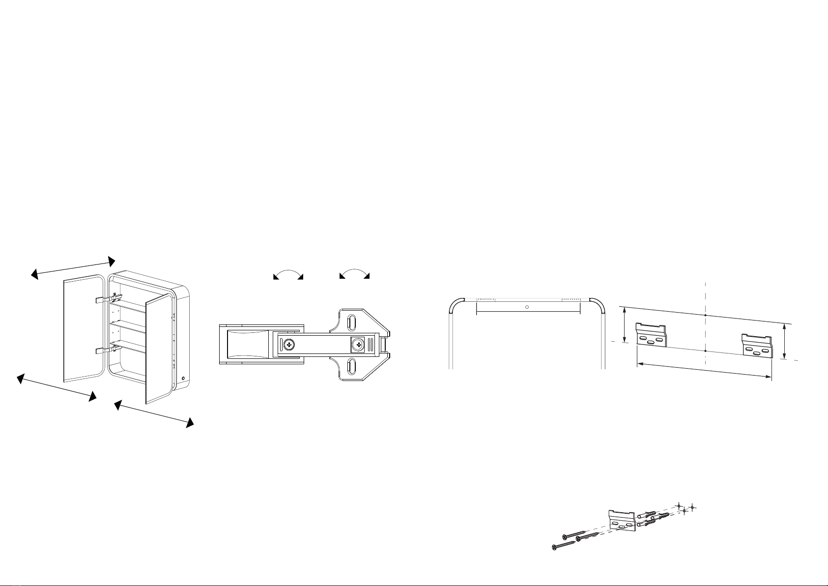
1.8 – Hang the cabinet on the wall brackets and check its level. Make sure the wall
brackets have entered the slots and the cabinet is not resting on the edge of the wall
brackets.
1.9 – Mark the hole on the lower section of the cabinet backboard (1.9). Take the
cabinet off the wall.
1.10 – Drill and fit the wall plug into the hole just marked.
Step 1 - Installing the cabinet
1.1 – Using a pencil, mark on the wall where you wish the centre of the top surface
of the cabinet to be (1.1).
1.2 – Measure 25mm vertically below this point and make a mark.
1.3 – Using a spirit level, draw a line of distance X centred on this point and parallel
with the floor.
1.4 – Align the outer edge of the wall brackets with the ends of this line X.
1.5 – Using the wall brackets as a guide, mark the hole positions.
1.6 – Drill the marked holes and fit the wall plugs.
1.7 – Screw the wall brackets into place ensuring the screws are fully tightened but
take care not to overtighten.
Installation Procedure
C
-+
D
-+
D
-+
C
-+
(1.1)
Top of cabinet
25mm
Centre Line
x
(x)
Measure this distance for postion
of ends of wall brackets
Step 2 - Connecting to power
Important: Before connecting the cabinet to the mains supply, make sure the
electrical supply is switched off. It is recommended that the fuse is withdrawn or the
circuit breaker is switched off for the necessary circuit.
2.1 – Connect to mains electrical supply. Connections should be made in accord-
ance with the latest IEE regulations. This cabinet is manufactured to CLASS 1 and
requires an earth connection.
Step 3 - Finishing the installation
3.1 – Hang the cabinet on the wall brackets as shown in 1.8. Ensure the wall
brackets have entered the slots within the cabinet.
3.2 – Screw in the internal securing screw (3.2).
3.3 – Push in the shelf supports with the screw at the bottom (3.3).
3.4 – Slide the glass shelf into the shelf supports (3.4).
3.5 – Tighten the plastic screws. Do not over tighten as you may round off the
plastic screw head (3.5).
3.6 – Repeat steps 3.3 to 3.5 for the remaining shelves.
Step 4 - Turning the power on
Important: Before turning the power back on, make sure the cabinet is securely
installed and all electrical connections are safe to turn on.
4.1 – If the fuse was removed, re-insert the fuse and switch power on. If circuit breaker
was switched off, turn back on.
4.2 – Check the functionality of the cabinet, operating instructions can be found on
page 7.
Step 5 - Door Alignment
6.1 – Adjust the cabinet doors using the adjustment screws on the hinges. As shown
below.
C-
+
Page 6 Page 3