manuals.online logo
Brands
  1. Home
  2. •
  3. Brands
  4. •
  5. Roper Rhodes
  6. •
  7. Indoor Furnishing
  8. •
  9. Roper Rhodes PLATEAU AS515ALIL User manual

Roper Rhodes PLATEAU AS515ALIL User manual

Please retain for future reference. Instructions should be kept / passed to end-user once installation is complete.
INSTALLATION & AFTERCARE INSTRUCTIONS
LED CABINET PRODUCT INSTRUCTIONS
PLATEAU & SUMMIT CABINET - AS515ALIL, AS615ALIL
ELECTRICAL SAFETY INSTRUCTIONS
All fittings must be installed by a competent person, in accordance with current IEE wiring regulations.
If in doubt consult a qualified electrician
IMPORTANT
Always switch off the electrical supply at the mains during installation and maintenance. It is recommended
that the fuse is withdrawn or the circuit breaker is switched off for the necessary circuit before installation
commences.
The product must be installed with a minimum distance of 150mm between the infrared sensor and any
adjacent wall or obstruction to ensure correct function of the sensor.
Fitting in Bathrooms is subject to the appropriate zone in accordance with IEE Regulations. This product is
suitable for zone 2 and outside zones. IT IS NOT suitable for installation in Zone 0 or Zone 1. It is also not
suitable for installation in saunas, steam rooms or shower cubicles. This product is only suitable for permanent
installation. DO NOT connect to a trailing plug and socket outlet. Although this product has an Ingress
Protection rating of IP44 it is only suitable for indoor use. Do not attach the product to surfaces that are damp
or otherwise electrically conductive.
INSTALLATION CARE & SAFETY
Wear suitable eye protection when drilling. Take care when using power tools near water - the use of a residual
current device (RCD) is advised. Beware of hidden cables or pipes. Take care if drilling on tiled surfaces in
case the drill slips. A piece of masking tape applied to the wall before marking out the fixing holes will stop the
drill from wandering.
DO NOT strike glass components with hard or pointed items. DO NOT place very hot or very cold items
against or in close proximity to glass surfaces unless an adequately thick insulation material is used to prevent
such items coming in contact with the glass.
The nominal thickness of the mirror glass used in this product is 5mm and is film backed for safety. If the glass
becomes chipped or broken replace immediately.
This product should be positioned well away from curtains and other fabrics. Never cover the mirror. This
product is heated, we recommend that it is turned off after use and should never be left on for prolonged
periods of time
This product could be dangerous and is only to be installed by a competent person.
CLEANING
It is recommended that the unit is cleaned with a soft, dry, non abrasive cloth when turned off. Never use
cleaning agents or abrasive materials on any type of surface finish. Do not allow moisture to come into contact
with the electrical components.
COMPLIANCE
This product complies with all relevant British
and European safety standards.
22
2
OUTSIDE
ZONES
2
ZONE
1
0.75m
2.25m
3.0m
0.6m 0.6m
0.75m
BATHROOM ZONES DIAGRAM
Distances from a bath tub or shower tray
Summit - AS615ALIL
AO.011.18.V2
The product must be installed with a
minimum distance of 150mm between
the infrared sensor and any adjacent
obstruction to ensure correct function
of the sensor (see diagram).
MIN
150mm
Plateau - AS515ALIL
PLATEAU & SUMMIT CABINET - AS515ALIL, AS615ALIL
LED CABINET PRODUCT INSTRUCTIONS
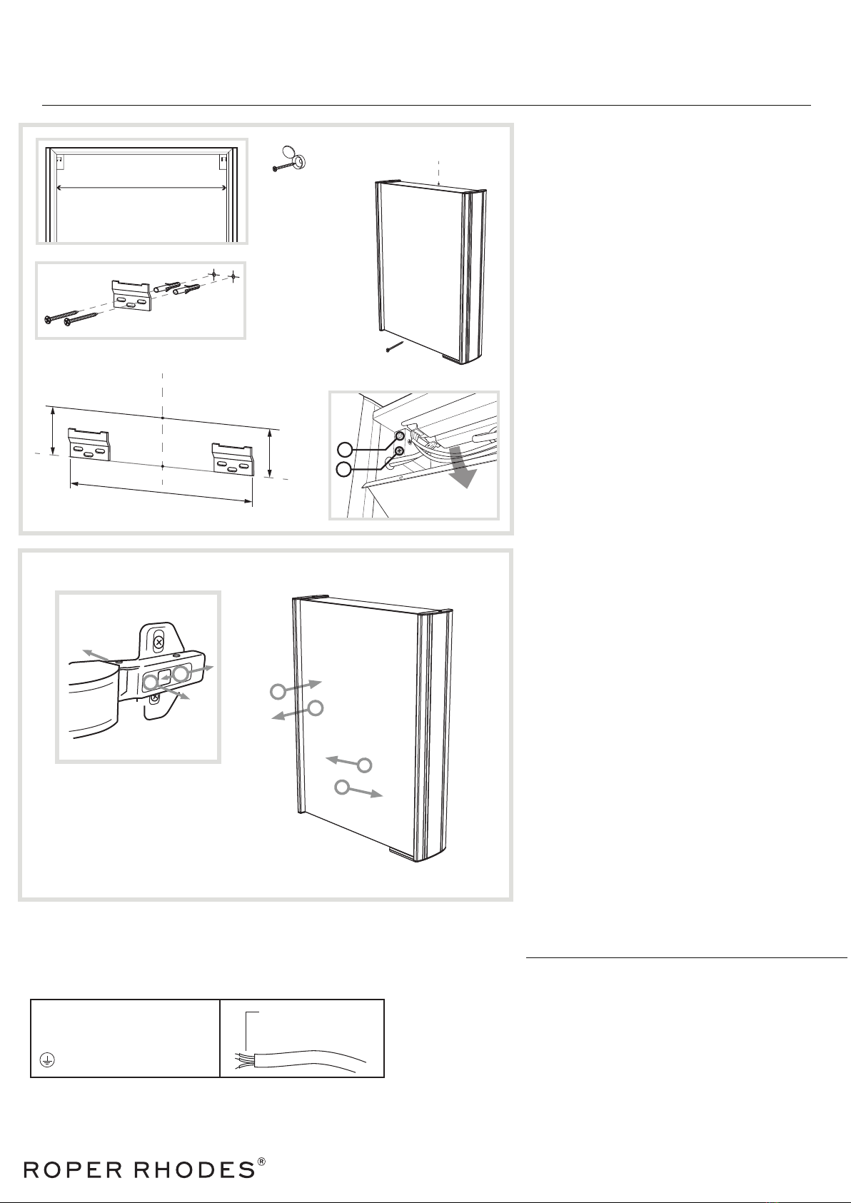
INSTALLATION PROCEDURE
Before commencing installation switch off electrical
supply at the mains.
The wall surface must be of suitable strength and
construction.
1. Remove the cabinet from the packaging taking special
care with the mirrored doors and glass shelves
2. Using a pencil, mark on the wall where you wish the
centre of the top surface of the cabinet to be (2.1).
3. Measure 60mm vertically below this point and make a
mark. (3.1)
4. Using a spirit level, draw a line of distance X centred
on this point and parallel with the floor.
5. Align the outer edge of the wall brackets with the ends
of this line (5.1 & 5.2)
6. Using the wall brackets as a guide, accurately mark
the hole positions.
7. Drill the marked holes and fit the wall plugs.
NOTE: The wall plugs supplied are only suitable for solid
stone / brick walls. For plasterboard walls use specialist
wall plugs.
8. Screw the wall brackets into place ensuring the screws
are fully tightened but take care not to overtighten.
9. Hang the cabinet on the wall brackets and check its
level (finer adjustments can be made by opening the
cabinet’s top electrical compartment and turning screw A
on each individual hanger until level).
10. When the cabinet is level mark the hole on the lower
section of the cabinet backboard (10.1). Take the cabinet
off the wall.
11. Drill and fit the wall plug into the lower section
backboard hole just marked.
12. Before making any electrical connections (or
performing any maintenance) turn off the mains electricity
supply.
13. Using the connection wire found on the rear of the
cabinet, make the necessary connections in accordance
with the current IEE regulations. A second person will
need to hold the cabinet in place whilst electrical
connections are made.
14. Hang the cabinet on the wall brackets and tighten
screw B within the electrical compartment. This will pull
the cabinet closer to the wall.
15. After all cabinet hanger adjustments are complete,
close electrical compartment.
16. Screw in the internal securing screw (16.1).
17. Once the installation has been completed, restore the
mains power and test the functions of the cabinet.
Roper Rhodes Ltd, Brassmill Lane Trading Estate, Bath, BA1 3JF
Tel:01225 303 900 | Email: [email protected]
www.roperrhodes.co.uk
Strip wires to a suitable
length. DO NOT connect
to a plug & socket outlet.
THIS PRODUCT IS MANUFACTURED TO CLASS I
CATEGORY AND MUST HAVE AN EARTH CONNECTION.
! IF IN DOUBT CONSULT YOUR ELECTRICIAN !
COLOUR CODING:
L - Live = Brown
N - Neutral = Blue
- Earth = Green & Yellow
OPERATING INSTRUCTIONS
The cabinet comes with LED lighting, which is controlled via an IR sensor.
Turn cabinet ON/OFF
To turn the cabinet on/off, slowly wave your hand in front of the IR sensor.
Measure this distance for position
of ends of wall brackets
WALL MOUNTING
A
B
Internal securing
screw (step 16)
(x)
(2.1)
(3.1)
Top of cabinet
60mm
Centre Line
x
(5.1)
(5.2)
(16.1)
(10.1)
(2.1)
Centre Line
HINGE ADJUSTMENT
C
C
D
D
To make door depth adjustments,
turn screw C.
To make horizontal door adjustments,
turn screw D.
C
D
Note: Cabinet for illustrative purposes.
Please match your components to the
relevant diagram

This manual suits for next models

1

Other Roper Rhodes Indoor Furnishing manuals

Roper Rhodes SYSTEM Series User manual

Roper Rhodes

Roper Rhodes SYSTEM Series User manual

Roper Rhodes SYC050 User manual

Roper Rhodes

Roper Rhodes SYC050 User manual

Roper Rhodes FR60RW Instruction sheet

Roper Rhodes

Roper Rhodes FR60RW Instruction sheet

Roper Rhodes US70AL User manual

Roper Rhodes

Roper Rhodes US70AL User manual

Roper Rhodes Hyper MLE370 User manual

Roper Rhodes

Roper Rhodes Hyper MLE370 User manual

Roper Rhodes FO70AL Parts list manual

Roper Rhodes

Roper Rhodes FO70AL Parts list manual

Roper Rhodes ENVY 700 User manual

Roper Rhodes

Roper Rhodes ENVY 700 User manual

Roper Rhodes Diverge Floor Mounted Unit User manual

Roper Rhodes

Roper Rhodes Diverge Floor Mounted Unit User manual

Roper Rhodes HAMPTON User manual

Roper Rhodes

Roper Rhodes HAMPTON User manual

Roper Rhodes EMINENCE EM70RAL User manual

Roper Rhodes

Roper Rhodes EMINENCE EM70RAL User manual

Roper Rhodes MLE420 Parts list manual

Roper Rhodes

Roper Rhodes MLE420 Parts list manual

Roper Rhodes ASCENSION FEVER AS251 Parts list manual

Roper Rhodes

Roper Rhodes ASCENSION FEVER AS251 Parts list manual

Roper Rhodes Cypher 600 Unit FM Parts list manual

Roper Rhodes

Roper Rhodes Cypher 600 Unit FM Parts list manual

Roper Rhodes Hampton HAM400FC User manual

Roper Rhodes

Roper Rhodes Hampton HAM400FC User manual

Popular Indoor Furnishing manuals by other brands

Riverside Furniture Falls Creek Entertainment 16146 Assembly instructions

Riverside Furniture

Riverside Furniture Falls Creek Entertainment 16146 Assembly instructions

gbo Ludovic Glass Cabinet manual

gbo

gbo Ludovic Glass Cabinet manual

Balt Role Model 89821 Assembly instructions

Balt

Balt Role Model 89821 Assembly instructions

New Classic Furniture B1563-400 Assembly instructions

New Classic Furniture

New Classic Furniture B1563-400 Assembly instructions

physa AVERSA EX10040280 user manual

physa

physa AVERSA EX10040280 user manual

GPM DINCAIBLK Assembly instructions

GPM

GPM DINCAIBLK Assembly instructions

Target 5948307T Assembly instructions

Target

Target 5948307T Assembly instructions

LDI SAFCO Whiffle 3906 instructions

LDI

LDI SAFCO Whiffle 3906 instructions

STILFORD JBSPCS12WN Assembly instructions

STILFORD

STILFORD JBSPCS12WN Assembly instructions

GFW MILTON BEDSIDE TABLE quick start guide

GFW

GFW MILTON BEDSIDE TABLE quick start guide

Mocka Parker Desk Assembly instructions

Mocka

Mocka Parker Desk Assembly instructions

Dorel DA6921 instruction manual

Dorel

Dorel DA6921 instruction manual

Wampat W04H4121G Assembly instructions

Wampat

Wampat W04H4121G Assembly instructions

Ambivalenz Flapps manual

Ambivalenz

Ambivalenz Flapps manual

Accuride DZ3932-0030EC installation guide

Accuride

Accuride DZ3932-0030EC installation guide

Costway HW66508 user manual

Costway

Costway HW66508 user manual

dams Flux FL-MM3 Assembly instructions

dams

dams Flux FL-MM3 Assembly instructions

Furniture of America CM7129Q Assembly instructions

Furniture of America

Furniture of America CM7129Q Assembly instructions

manuals.online logo
manuals.online logoBrands
  • About & Mission
  • Contact us
  • Privacy Policy
  • Terms and Conditions

Copyright 2025 Manuals.Online. All Rights Reserved.