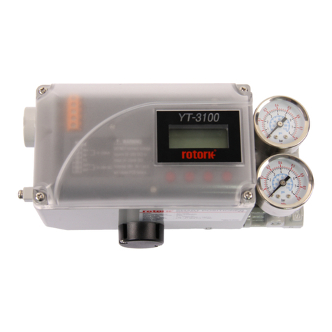
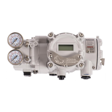
Smart Positioner
YT-2600 series Product manual
Ver. 1.30 3
6.2 Variable Orifice Adjustment............................................................................................................... 32
7Maintenance ............................................................................................................................................. 33
7.1 Supply air........................................................................................................................................... 33
7.2 Seals.................................................................................................................................................. 33
8Auto Calibration and PCB Operation..................................................................................................... 34
8.1 Warning.............................................................................................................................................. 34
8.2 Button Description ............................................................................................................................. 34
8.3 Run Mode (RUN)............................................................................................................................... 35
8.4 Auto Calibration mode (AUTO CAL).................................................................................................. 35
8.4.1 AUTO1 Calibration (AUTO1)......................................................................................................... 36
8.4.2 AUTO2 Calibration (AUTO2)......................................................................................................... 36
8.4.3 AUTO3 Calibration (AUTO3)......................................................................................................... 36
8.5Manual Mode (MANUAL)................................................................................................................... 37
8.6 Parameter Mode (PARAM)................................................................................................................ 38
8.6.1 Dead-Zone (dEAdZONE, %) ......................................................................................................... 38
8.6.2 P1 Value (KP1).............................................................................................................................. 39
8.6.3 D1 Value (Kd1) .............................................................................................................................. 39
8.6.4 P2 (KP2) and D2 (Kd2) values ...................................................................................................... 39
8.6.5 P_ (KP_) and D_ (Kd_) Values...................................................................................................... 39
8.6.6 PT1 (PT1) and PT2 (PT2) Values.................................................................................................. 40
8.6.7 Period T (PERIOd T) ..................................................................................................................... 40
8.6.8 Auto DZ (AUTO dZ)....................................................................................................................... 40
8.7 Hand Calibration Mode (HAND CAL) ................................................................................................ 41
8.7.1 Zero-Point (PV_ZERO) and End-Point (PV_END) for Valves....................................................... 41
8.7.2 Zero-Point (TR_ZERO) and End-Point (TR_END) for Transmitter ............................................... 42
8.7.3 Normal / Reverse Feedback Signal (TR NORM / REVS).............................................................. 43
8.7.4 Normal / Reverse HART Signal (HT NORM / REVS).................................................................... 43
8.8 Valve Mode (VALVE)......................................................................................................................... 44
8.8.1 Acting Adjustment (ACT RA / dA).................................................................................................. 44
8.8.2 Valve flow Characteristic Adjustment (CHAR)............................................................................... 45
8.8.3 User defining flow Characteristics (USER SET)............................................................................ 46
8.8.4 Tight Shut Open (TSHUT OP)....................................................................................................... 48
8.8.5 Tight Shut Close (TSHUT CL) ....................................................................................................... 48
8.8.6 Split Range Mode (SPLIT)............................................................................................................. 49
8.9 View Mode (VIEW) ............................................................................................................................ 50
9Error and Warning Code ......................................................................................................................... 52
9.1 Error code which is displayed during Auto calibration....................................................................... 52
9.2 Error code which is displayed while using the product...................................................................... 53
9.3 Error code which can be checked from View mode .......................................................................... 54
9.4 Warning code which can be checked from View mode..................................................................... 55
