manuals.online logo
Brands
  1. Home
  2. •
  3. Brands
  4. •
  5. Ruckus Wireless
  6. •
  7. Wireless Access Point
  8. •
  9. Ruckus Wireless T811-CM User manual

Ruckus Wireless T811-CM User manual

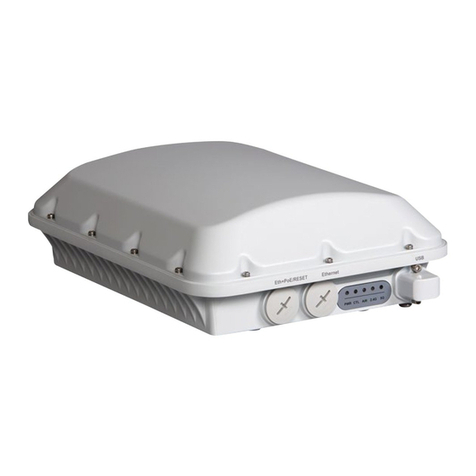
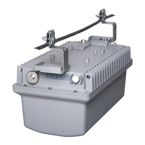
T811-CM Access Point
Quick Setup Guide
NOTE: The minimum soware revision for the T811-CM is SmartZone
(SZ) 3.4.2, or 3.6.1, or later. (SZ 3.5.x and 3.6 do not support the T811-
CM).
This Quick Setup Guide provides brief instrucons on how to eld-install
the Ruckus Wireless T811-CM access point (AP). For detailed informaon
on planning the installaon, performing a site survey, and operang the
T811-CM, refer to the T811-CM Cable Modem Access Point Installaon
Guide, available at hps://support.ruckuswireless.com.
WARNING! Only trained and qualied personnel should be allowed to
install, replace, or service this equipment. Only to be installed in
restricted access areas.
WARNING! Installaon of this equipment must comply with local and
naonal electrical codes.
CAUTION! Make sure that you form a 80mm - 130mm (3”-5”) drip loop
in any cable that is aached to the AP or the building. This will prevent
water from running along the cable and entering the AP or the building
where the cable terminates.
CAUTION! Be sure that grounding is available and that it meets local
and naonal electrical codes. For addional lightning protecon, use
lightning rods and lightning arrestors.
CAUTION! Make sure that proper lightning surge protecon
precauons are taken according to local electrical code.
WARNING! Ruckus Wireless strongly recommends that you wear eye
protecon before mounng the T811-CM.
This Guide in Other Languages
•请从以下网站获得该指南的简体中文版 hps://
support.ruckuswireless.com.
•Vous trouverez la version française de ce guide à l'adresse suivante
hps://support.ruckuswireless.com.
•このガイドの日本語版は hps://support.ruckuswireless.com でご覧
ください。
•이 가이드의 한국어 버전은 웹 사이트 (hps://
support.ruckuswireless.com) 에서 확인하시기 바랍니다.
•Veja a versão em português (Brasil) deste guia em hps://
support.ruckuswireless.com.
•Puede ver la versión en español (América Lana) de esta guía en hps://
support.ruckuswireless.com.
Before You Begin
Before deploying Ruckus Wireless products, please check for the latest
soware and the release documentaon.
•Release Notes and other user documentaon are available at hp://
support.ruckuswireless.com/documents.
•Soware upgrades are available at hp://support.ruckuswireless.com/
soware.
•Open source informaon is available at hp://
opensource.ruckuswireless.com.
•Soware license and limited warranty informaon are available at
hp://support.ruckuswireless.com/warranty.
Before deploying your Ruckus Wireless Access Point, verify that all items
listed in Package Contents are included in the package. If any item is
damaged or missing, nofy your authorized Ruckus Wireless sales
representave. Also, make sure that you have the required hardware
and tools.
Required Hardware and Tools
•No. 2 Phillips screwdriver bit
–Torque screwdriver (Ranges from 7 to 40 in-lbs)
•Small at-blade screwdriver
•Torque wrench and torque screwdriver with sockets
–7/16 wrench for F connector (30 in-lbs)
–11mm socket for aenuaon and impedance matching caps (35 in-
lbs)
–19mm socket for Strand nut (16 to 20 -lbs) and F-connector snger
(40 in-lbs)
•Long-nose pliers
•Electrical wire stripping and terminal crimping pliers
•Cable strand
Package Contents
A Ruckus Wireless T811-CM package contains the items listed below:
•Ruckus Wireless T811-CM unit with cable strand hangers, includes one
12mm long stainless steel M6x1 earth ground panhead screw with split
lock and at washers
•A one-meter green/yellow earth ground wire with ring terminal
•Safety cable kit
•Cable gland/cable gland extender:
–2 cable glands
–Cable gland extender
–Dual-hole cable gland insert for zip cord SFP ber
•Service Level Agreement/Limited Warranty Statement
•Regulatory Statement
•Declaraon of Conformity, if required
•T811-CM Access Point Quick Setup Guide
Mounng Instrucons
AP and CM MAC Addresses, Connectors and
Ground Point
The T811-CM MAC address label lists separate addresses for the internal
AP and the cable modem (CM).
The MAC address label (1 in the Figure below) is mounted on the end of
the T811-CM with the F type connector and the ground screw (2 and 3 in
the Figure). The following table describes the label, connector and the
ground point screw.
FIGURE 1 T811-CM MAC address label, F type connector and ground
point
TABLE 1 Connectors and ground point on the T811-CM
No. Label Descripon
1 MAC
Address
label
locaon
Labels include separate addresses for the
internal AP and CM.
2 Coaxial cable
connector
F type, connects to the CMTS at the head
end using a tap on the plant, and provides
AC POC to the T811-CM. For more
informaon, refer to "Powering the T811-CM
with POC."
3Oponal
External
Ground
Earth Point
The T811-CM is normally earth-grounded by
the cable strand. However, if the cable
strand is not earth grounded, then connect
an external earth ground to the T811-CM
using this screw-and-washer set.
LEDs and Ports
The following gure illustraons the locaons of the LEDs and ports on the
T811-CM, and the table below provides descripons of each feature.
Use the eight LEDs to check the status of the access point and cable
modem.
Copyright © 2023 CommScope, Inc. All rights reserved. Page 1 of 4
Published January 2023, Part Number 800-71744-001 Rev D
FIGURE 2 T811-CM LEDs and ports
TABLE 2 T811-CM LEDs and Ports
No
.
Label Descripon
1 POWER O: AP o.
Blinking red: Boot up in process.
Solid Green: AP on.
2 CM DS Blinks when searching for downstream (DS),
then solid when DS is locked.
3 CM US /
SFP Acvity
O when upstream (US) is searching, and then
blinks as upstream power is increased/ranged
and then solid when upstream is locked.
In SFP mode, this LED blinks with SFP Acvity.
4 ONLINE O: No backhaul connecon detected.
Blinking green: Obtaining IP address and
conguraon le.
Solid green: Cable Modem backhaul Online.
Solid amber: SFP ber backhaul Online.
5 CTL On when the Access Point is being managed
by a Ruckus Wireless controller.
6 AIR O: The Access Point is operang in
standalone mode, or the uplink is through its
wired Ethernet interface. The wireless uplink
interface is down.
Solid green: The AP is operang as a Mesh AP
(MAP), and the wireless signal to its uplink AP
is good.
7 2.4 GHz O: The 2.4GHz WLAN service is down.
TABLE 2 T811-CM LEDs and Ports (connued)
Solid amber: The 2.4GHz WLAN service is up.
No clients are associated.
Solid green: The 2.4GHz WLAN service is up
and at least one client is associated.
8 5 GHz O: The 5GHz WLAN service is down.
Solid amber: The 5GHz WLAN service is up,
but no clients are associated/connected.
Solid green: The 5GHz WLAN service is up and
at least one client is associated.
9 USB Port USB port for IoT devices
Max Dimensions: 6 cm x 2 cm x 1.1 cm
Max Weight: 8 ounces
Max Power: 0.5 W
Interface: USB 2.0 Type-A plug
10 Eth Port /
Reset
Buon
1 x 10/100/1000 PoE Out port (802.3at)
Supports PoE PSE (802.3at) 30W
Reset Buon: Depress quickly to reboot both
the AP and the CM (4 sec or less). Press and
hold for 5-10 seconds to perform a full reset to
factory default sengs.
Connector: RJ-45
11 SFP Fiber
interface
Supports the following types of SFP modules:
GPON
EPON
1000BaseLX
See the Installaon Guide for more details.
Ports for Cable Aenuaon and Impedance
Matching
The following gure shows the two ports on the T811-CM that are used for
aenuaon and impedance matching. For details on how to perform the
aenuaon and impedance matching see the Installaon Guide.
FIGURE 3 Aenuaon and impedance ports
1. Aenuaon port 2. Impedance port
Mounng the T811-CM
To mount the T811-CM assembly on a cable strand, you need to secure the
cable clamps that are aached to the strand interface to the cable strand.
1. Slightly loosen the nuts that fasten the two cable clamps to the strand
interface, enough for the strand support cable to t into the cable
clamps.
2. Place the cable clamps on the strand support cable.
3. Tighten the two cable clamp nuts to 22 to 27N.m (16 to 20 -lbs) to
secure the mounng.
Earth Grounding the T811-CM
The cable strand is usually earth-grounded, and mounng the T811-CM on
the cable strand earth grounds the T811-CM chassis as well; if this is the
case, skip this procedure and connue with the "Installing the Cable Power
Tap" task.
CAUTION! Be sure that earth grounding is available and that it meets
local and naonal electrical codes. For addional lightning protecon,
use lightning rods and lightning arrestors.
If the cable strand is not earth-grounded, then connue with the
following:
1. The color coding of ground wires varies by region. Before compleng
this step, check your local wiring standards for guidance.
2. Using the factory-supplied ground screw and washers, use the
factory-supplied earth ground wire with ring terminal to connect a
good earth ground to the T811-CM using the chassis ground screw
shown in Figure 1, item #3.
NOTE: The T811-CM includes one 12mm stainless steel M6x1
earth ground screw with split lock and at washers. Make sure
that any replacement screw is no longer than 12mm. If a screw is
longer than 12mm, it can damage the T811-CM chassis.
Installing the Cable Power Tap
The CATV coaxial cable used in the eld deployment must have 60 to 90
VAC power mulplexed with the RF signal on the coaxial cable, since the
T811-CM F-type connector is used for both electrical power and the RF
signal (when the cable modem is used for backhaul). Maximum current
requirement is up to 3.5A, depending on voltage.
NOTE: In SFP mode, only VAC is needed.
Ruckus Wireless recommends installing a cable power tap (Antronix
MGT2000-SDPE tap, or equivalent) close to the T811-CM. Refer to the
Copyright © 2023 CommScope, Inc. All rights reserved. Page 2 of 4
Published January 2023, Part Number 800-71744-001 Rev D
manufacturer's instrucons to mount the cable power tap on the coaxial
cable.
NOTE: If the F-type connector on the T811-CM is damaged, refer to
"Appendix C: Replacing the F Connector Adapter" in the Installaon
Guide.
1. Using a customer-supplied cable, connect any port on the cable
power tap to the F-type connector on the T811-CM.
2. Tighten the cable F-type connectors to 3.4 N.m or 30 in-lbs.
Powering the T811-CM with POC
60 to 90 VAC POC is used when the T811-CM is mounted on a cable strand
and powered via an F-type coaxial cable connected to the HFC cable plant.
1. Remove the power jumper from the power tap to remove AC power
out of the power tap.
2. Insert the F-type coaxial cable that is connected to the HFC cable
plant to the F-type connector on the T811-CM. Power is supplied over
the CATV coax through a power passing tap. The tap is connected to
F-type connector on the T811-CM as shown in AP and CM MAC
Addresses, Connectors and Ground Point.
3. Finger ghten the coaxial cable connector and then ghten to 3.4N.m
(30in-lbs).
4. Wait unl the T811-CM PWR, CM DS, CM US, and ONLINE LEDs stop
ashing and then remain on.
Checking the T811-CM Signal Level with an RF
Power Meter (Oponal)
The CMAP cable modem is just like a standard DOCSIS 3.1 modem installed
at home.
Connect an RF power meter to the cable from the cable power tap to
measure the downstream power coming from the cable.
The power level should be between +15dBmV and -15dBmV.
Accessing Cable Aenuator and Impedance
Matching Ports
1. Use a 7/16" (11mm) socket or wrench to remove the screw-in access
plug covering the aenuator and impedance ports. See Figure 3 for
the locaon of these ports.
2. Refer to the Installaon Guide for aenuator and impedance
matching instrucons.
3. When adjustments are complete, replace plugs and ghten to a
torque seng of 35 in-lbs.
Installing USB IoT Dongle
For details, refer to the Installaon Guide.
Accessing the Diagnosc Ethernet Port
In order to access the AP or CM web or CLI interfaces directly, you will
need to connect an Admin PC to the T811-CM via the diagnosc Ethernet
port.
1. Collect the required equipment and informaon:
•The IP address assigned by the DHCP server.
•An administrave computer congured as described in the
"Preparing the Administrave Computer" task in the Installaon
Guide.
•One Cat5e or beer Ethernet cable.
•Large at-blade screwdriver.
2. Use a large at-blade screwdriver to remove the reset buon and
diagnosc Ethernet port screw-in access plug.
3. Connect one end of an Ethernet cable to the Ethernet port on the
T811-CM, and then connect the other end to the administrave
computer’s Ethernet port.
4. On the administrave computer, open a web browser window.
5. In the address or locaon bar, enter the IP address that is assigned to
the cable modem, for instance:
•192.168.100.1, OR
•192.168.100.2, OR
•<DHCP-assigned IP address>
The web interface displays a login prompt.
6. Log in to the CM or AP web interface as described in Logging Into the
CM or AP Web Interface.
7. Perform administraon tasks as required.
8. When you have completed the tasks, replace the access plug and
ghten to a torque seng of 7 in-lbs.
Conguring the Downstream Frequency
The Congure Status page allows you to set the rst downstream
frequency to be tried by the cable modem.
Conguring the inial downstream frequency enables the device to quickly
obtain a direct frequency lock with the CMTS upon bootup and helps to
save several minutes of scanning for an available downstream frequency
from the CMTS.
1. Log into the Status page as described in "Logging Into the CM Web
Interface" task.
2. Click Congure in the le sidebar. The CM Web interface displays the
Congure Status page.
FIGURE 4 Congure Status page
3. In the Congure DS Frequency text box, enter the downstream
frequency (in Hertz) that you want the cable modem to use to
connect to the CMTS when it boots up.
4. Click Set Values and Reboot to have the cable modem save your
changes and reboot.
Reboong and Reseng the AP and CM
CAUTION! Performing this procedure resets the AP and CM parts of the
T811-CM to their factory default sengs. If you want to reset only the
CM component to its factory default sengs, then perform the
procedure described in Reboong and Factory-Reseng the CM
instead.
NOTE: Reseng the AP and CM to factory default sengs erases all the
sengs that you have previously congured. Also note that reseng
and/or reboong the AP and CM disrupts all wireless network
communicaons through this device.
There are dierent ways to reboot or reset the AP and CM parts of the
T811-CM:
•Using the Reset Buon Inside the AP
•Remotely Reboong and Factory Reseng the AP
Using the Reset Buon Inside the AP
You can reset the AP and CM to their factory default sengs by pressing
the reset buon behind the access plug covering the Ethernet port.
1. Make sure that the AP is powered on.
2. Use a large at blade screwdriver to remove the screw-in access plug
covering the reset buon and Ethernet port.
3. Locate the reset buon under the access plug.
FIGURE 5 Locaon of the reset buon
4. Using a pen or a similar pointed object, press the reset buon for 1-4
seconds to reboot the AP and CM. Press and hold the reset buon for
5-9 seconds to reset the AP and CM to factory defaults.
5. Replace the access plug, and ghten to a torque of 7 in-lbs (0.7909
Nm).
You have completed reseng the AP and CM to their factory default
sengs and/or reboong the AP and CM.
Copyright © 2023 CommScope, Inc. All rights reserved. Page 3 of 4
Published January 2023, Part Number 800-71744-001 Rev D
Remotely Reboong and Factory Reseng the AP
You can also reboot and/or factory reset the AP using SNMP.
NOTE: Before starng this procedure, you must rst obtain the related
MIBs from Ruckus Wireless. Contact your authorized Ruckus Wireless
sales representave or Ruckus Wireless Support. Visit hps://
support.ruckuswireless.com/contacts for Ruckus Wireless Support
contact informaon.
1. Connect the administrave computer to the same network as the
T811-CM.
2. Start your MIB browser.
3. Load the Ruckus Wireless MIBs onto the MIB browser.
4. In the MIB browser, specify the IP address of the T811-CM AP. (You
can obtain this informaon from the DHCP server on the network.)
5. Find the OID for the T811-CM reset and reboot controls. Refer to the
Ruckus Wireless Access Point SNMP Reference Guide, available from
support.ruckuswireless.com, for AP-specic SNMP MIBs.
•ruckusT811CMControlLED OID is: .1.3.6.1.4.1.25053.3.1.4.97.3
6. Then do the following:
•To so reset the AP, set the value to 10 (soResetAP).
•To factory-reset the AP, set the value to 12 (factoryResetAP).
You have completed remotely reboong or factory-reseng the access
point using SNMP.
Installing the Safety Cable
1. Undo one of the strand mount bracket 1/4 20 nuts and thread the
security cable through the mounng bracket and through the eye on
the cable itself, as shown in the following illustraon.
2. Aach the other end of the safety cable to the strand cable or other
xed anchor.
3. Reinstall the nut and torque to 85 in-lbs.
FIGURE 6 Aach the safety cable to the strand mount bracket
Copyright © 2023 CommScope, Inc. All rights reserved. Page 4 of 4
Published January 2023, Part Number 800-71744-001 Rev D
Other manuals for T811-CM

2

Other Ruckus Wireless Wireless Access Point manuals

Ruckus Wireless MediaFlex 7811 User manual

Ruckus Wireless

Ruckus Wireless MediaFlex 7811 User manual

Ruckus Wireless R350 User manual

Ruckus Wireless

Ruckus Wireless R350 User manual

Ruckus Wireless zoneflex t301n Installation instructions manual

Ruckus Wireless

Ruckus Wireless zoneflex t301n Installation instructions manual

Ruckus Wireless ZoneFlex 7352 User manual

Ruckus Wireless

Ruckus Wireless ZoneFlex 7352 User manual

Ruckus Wireless ZoneFlex R500 User manual

Ruckus Wireless

Ruckus Wireless ZoneFlex R500 User manual

Ruckus Wireless Q710 LTE User manual

Ruckus Wireless

Ruckus Wireless Q710 LTE User manual

Ruckus Wireless R750 User manual

Ruckus Wireless

Ruckus Wireless R750 User manual

Ruckus Wireless SmartCell 8800-S User manual

Ruckus Wireless

Ruckus Wireless SmartCell 8800-S User manual

Ruckus Wireless E510 User manual

Ruckus Wireless

Ruckus Wireless E510 User manual

Ruckus Wireless ZoneFlex H500 User manual

Ruckus Wireless

Ruckus Wireless ZoneFlex H500 User manual

Ruckus Wireless T750 User manual

Ruckus Wireless

Ruckus Wireless T750 User manual

Ruckus Wireless Q910 User manual

Ruckus Wireless

Ruckus Wireless Q910 User manual

Ruckus Wireless T610 User manual

Ruckus Wireless

Ruckus Wireless T610 User manual

Ruckus Wireless ZoneFlex R710 User manual

Ruckus Wireless

Ruckus Wireless ZoneFlex R710 User manual

Ruckus Wireless ZoneFlex 7343 User manual

Ruckus Wireless

Ruckus Wireless ZoneFlex 7343 User manual

Ruckus Wireless ZoneFlex series User manual

Ruckus Wireless

Ruckus Wireless ZoneFlex series User manual

Ruckus Wireless T300 Installation instructions manual

Ruckus Wireless

Ruckus Wireless T300 Installation instructions manual

Ruckus Wireless ZoneFlex 7352 User manual

Ruckus Wireless

Ruckus Wireless ZoneFlex 7352 User manual

Ruckus Wireless zoneflex t301n User manual

Ruckus Wireless

Ruckus Wireless zoneflex t301n User manual

Ruckus Wireless C500 User manual

Ruckus Wireless

Ruckus Wireless C500 User manual

Ruckus Wireless ZoneFlex R500 User manual

Ruckus Wireless

Ruckus Wireless ZoneFlex R500 User manual

Ruckus Wireless C500 User manual

Ruckus Wireless

Ruckus Wireless C500 User manual

Ruckus Wireless VF2811 User manual

Ruckus Wireless

Ruckus Wireless VF2811 User manual

Ruckus Wireless ZoneFlex 7762-S User manual

Ruckus Wireless

Ruckus Wireless ZoneFlex 7762-S User manual

Popular Wireless Access Point manuals by other brands

Cisco Aironet 1570 Series installation guide

Cisco

Cisco Aironet 1570 Series installation guide

MikroTik mAP 2nD manual

MikroTik

MikroTik mAP 2nD manual

D-Link NUCLIAS CONNECT DIS-3650AP user guide

D-Link

D-Link NUCLIAS CONNECT DIS-3650AP user guide

HP ProCurve RSVLC-0501 Installation and getting started guide

HP

HP ProCurve RSVLC-0501 Installation and getting started guide

NETGEAR WG602v4 - Wireless Access Point Reference manual

NETGEAR

NETGEAR WG602v4 - Wireless Access Point Reference manual

HMS Networks Anybus user manual

HMS Networks

HMS Networks Anybus user manual

AMP USB Bridge Wifi and RF quick start guide

AMP

AMP USB Bridge Wifi and RF quick start guide

Ruijie Networks RG-SAP815-SP Hardware  installation and reference guide

Ruijie Networks

Ruijie Networks RG-SAP815-SP Hardware installation and reference guide

Intellinet 524704 user manual

Intellinet

Intellinet 524704 user manual

ALTA LABS AP6-Pro quick start guide

ALTA LABS

ALTA LABS AP6-Pro quick start guide

Edge-Core WA4101-Cradle user guide

Edge-Core

Edge-Core WA4101-Cradle user guide

San Jose WIA3300-20 user manual

San Jose

San Jose WIA3300-20 user manual

Honeywell FocusBT AP-010-BT Specifications

Honeywell

Honeywell FocusBT AP-010-BT Specifications

Ruijie RG-AP840-L Hardware  installation and reference guide

Ruijie

Ruijie RG-AP840-L Hardware installation and reference guide

Minitar MNWAPGR user manual

Minitar

Minitar MNWAPGR user manual

AmbiCom WL1100B-AP Product specifications

AmbiCom

AmbiCom WL1100B-AP Product specifications

H3C WA538 installation guide

H3C

H3C WA538 installation guide

Blake UK PROception The Bridge Setup guide

Blake UK

Blake UK PROception The Bridge Setup guide

manuals.online logo
manuals.online logoBrands
  • About & Mission
  • Contact us
  • Privacy Policy
  • Terms and Conditions

Copyright 2025 Manuals.Online. All Rights Reserved.