Rupes LH19E User manual

2 - Lucidatrici
4 - Polishers
6 - Lustreuses
8 - Poliermaschinen
10 - Pulidoras
12 - Haakse poetsmachine
14 - Полировальная машина
16 - Lucidatrici
18 - Polishers
20 - Lustreuses
22 - Poliermaschinen
24 - Pulidoras
26 - Haakse poetsmachine
28 - Полировальная машина
30 - Lucidatrici
32 - Polishers
34 - Lustreuses
36 - Poliermaschinen
38 - Pulidoras
40 - Haakse poetsmachine
42 - Полировальная машина
44 - Lucidatrici
46 - Polishers
48 - Lustreuses
50 - Poliermaschinen
52 - Pulidoras
LH 16ENS - LH18ENS - LH22N - LH22EN
ISTRUZIONI ORIGINALI PER L'USO E LA MANUTENZIONE
ORIGINAL OPERATING AND MAINTENANCE INSTRUCTIONS
NOTICE ORIGINAL D'EMPLOI ET D'ENTRETIEN
ORIGINAL-BEDIENUNGS-UND WARTUNGSANLEITUNG
INSTRUCCIONES ORIGINAL DE USO Y MANUTENCION
AANWIJZINGEN VOOR HET GEBRUIK EN HET ONDERHOUD ORIGINEEL
ИНСТРУКЦИЯ ПО ЭКСПЛУАТАЦИИ И БСЛУЖИВАНИЮ1ОРИГИНАЛЬНЫЙ
ISTRUZIONI ORIGINALI PER L'USO E LA MANUTENZIONE
ORIGINAL OPERATING AND MAINTENANCE INSTRUCTIONS
NOTICE ORIGINAL D'EMPLOI ET D'ENTRETIEN
ORIGINAL-BEDIENUNGS-UND WARTUNGSANLEITUNG
INSTRUCCIONES ORIGINAL DE USO Y MANUTENCION
LH19E
Via Marconi, 3A - Loc. Vermezzo 20071
VERMEZZO CON ZELO (Mi) - Italy
Tel. +39 02 946941 - Fax +39 02 94941040
e-mail: info_rupes@rupes.it - web: www.rupes.com
IT Lucidatrice ISTRUZIONI ORIGINALI PER L’USO ...................................................................... 4
EN Polisher ORIGINAL OPERATING INSTRUCTIONS................................................................ 7
FR Polisseuse TRADUCTION DES INSTRUCTIONS DE FONCTIONNEMENT ORIGINALES............. 10
DE Polierer ÜBERSETZUNG DES ORIGINALBETRIEBSANLEITUNG.......................................... 13
ES Pulidora TRADUCCIÓN DEL MANUAL DE INSTRUCCIONES ORIGINAL............................... 16
PT Polidora TRADUÇÃO DAS INSTRUÇÕES DE OPERAÇÃO ORIGINAIS................................... 19
NL Polijstmachine
VERTALING VAN ORIGINELE GEBRUIKSAANWIJZING...................................................... 22
FI Kiillotuskone ALKUPERÄISTEN KÄYTTÖOHJEIDEN KÄÄNNÖS
......................................................... 25
DA Poleremaskine OVERSÆTTELSE AF ORIGINALE BETJENINGSINSTRUKTIONER
...............................28
SV Polermaskin ÖVERSÄTTNING AV ORIGINAL DRIFTSINSTRUKTIONER
.......................................... 31
RU
Полировальная машина
ПЕРЕВОД ОРИГИНАЛЬНОЙ ИНСТРУКЦИИ ПО ЭКСПЛУАТАЦИИ
...................................... 34
PL Polerka TŁUMACZENIE ORYGINALNYCH INSTRUKCJI OBSŁUGI
......................................... 37
EL Στιλβωτής ΜΕΤΑΦΡΑΣΗ ΠΡΩΤΟΤΥΠΩΝ ΟΔΗΓΙΩΝ ΛΕΙΤΟΥΡΓΙΑΣ
...............................................40
BG Полираща машина ПРЕВОД НА ОРИГИНАЛНИ ИНСТРУКЦИИ ЗА ЕКСПЛОАТАЦИЯ
...........................43
CS Leštička PŘEKLAD ORIGINÁLNÍHO NÁVODU K OBSLUZE
.......................................................46
ET Poleerija ORIGINAALKASUTUSJUHENDI TÕLGE
......................................................................... 49
HI
.................................................... 52
HU Polírozó AZ EREDETI HASZNÁLATI UTASÍTÁS FORDÍTÁSA
................................................... 55
LV Pulētājs ORIĢINĀLĀS LIETOŠANAS INSTRUKCIJAS TULKOJUMS
....................................... 58
LT Poliravimo mašina ORIGINALŲ NAUDOJIMO INSTRUKCIJŲ VERTIMAS
................................................. 61
RO Maşină de lustruit TRADUCEREA INSTRUCȚIUNILOR ORIGINALE DE OPERARE
................................. 64
SL Polirnik PREVOD IZVIRNIH NAVODIL ZA DELOVANJE
............................................................ 67
SK Leštička PREKLAD ORIGINÁLNEHO NÁVODU NA OBSLUHU
................................................. 70
TR Polisaj makinesi ORİJİNAL KULLANIM TALİMATLARININ TERCÜMESİ
................................................ 73
AR
................................................................... 76
CN 抛光机抛光机 操作说明书原件翻译操作说明书原件翻译
...................................................................................... 79
JP ポリッシャーポリッシャー 元の操作手順の翻訳元の操作手順の翻訳
......................................................................................... 83

6
2
9
10
2
9
3
11
1
5
8
14
4
10
7
12 (optional)
13 (optional)
LH19E

TYPE
INSULATION CLASS
POWER W
n NOMINAL RPM /min
ELECTRONIC SPEED CONTROL
BUFFER PAD AND BUFFER DIAMETER MAX
SPINDLE THREAD
WEIGHT according to EPTA-Procedure 01/2003 Kg
WARNINGS
The safety and accident prevention instructions are reported
in the “SAFETY INSTRUCTION” booklet which is an integral
part of these documents. This operating instructions manual
indicates the additional information required for the specic
use of the tool.
CORRECT USAGE
This tool is designed to be used as a polisher. Read all the
warnings, instructions, indications provided on drawings
and specications supplied with this tool. Failure to comply
with all the instructions provided below may cause electrical
shocks, re and/or serious injuries.
This tool is not intended to be used for smoothing, metal
brushing and cutting operations. The use of this tool for
unintended applications may cause hazards and injuries to
people.
The tool must be used with accessories that have been
specically designed or recommended by the manufacturer.
The xing of the accessory to the tool does not guarantee a
safe operation.
The rated speed of the accessories must be at least
equivalent to the maximum speed specied on the tool.
Using the accessories at speeds above the rated one, may
cause them to break or be projected into the air.
The external diameter and thickness of the accessories must
match the specications of the tool. Accessories with incorrect
dimensions cannot be adequately protected or controlled.
The conguration of accessories must match the tool.
The use of accessories that cannot be perfectly tted on the
tool may result in imbalance, excessive vibrations and in the
impossibility of controlling the tool.
Do not use damaged accessories. Before use, inspect all
the accessories. Inspect the supporting pads and verify
there are no cracks, tears or excessive wear. If the tool or
accessory has fallen, verify that it is not damaged or install
a new accessory. After inspecting or installing an accessory,
test the operation of the tool at maximum speed and without
load for one minute, keeping at a safety distance. If the
accessories are damaged, they will break during this test.
Wear personal protective equipment. According to the
the application, use face shield, mask or safety goggles.
According to the case, wear a dust mask, ear protection,
gloves and a smock capable of stopping small abrasive
fragments of the work piece. Eye protection must be able
to stop flying bits produced from the different operations
The dust mask or the respirator must be capable of filtering
particles produced by your work. Prolonged exposure to
high intensity noise can cause a loss of hearing. Keep the
people present at a safety distance with respect to the work
area. Anyone entering the work area must wear personal
protection equipment. The fragments of the work piece or
the broken accessories can fly off and cause injuries in the
immediate vicinity of the work area. Keep the tool only for
isolating gripping surfaces, while the operations are carried
out in which the cutting accessory may be in contact with
the hidden cables or with its cable. The contact between the
cutting accessory and the cable “under voltage” can also put
TECHNICAL SPECIFICATIONS
TRANSLATION OF ORIGINAL OPERATING INSTRUCTIONS 7
The values shown are based on a nominal voltage of 230V/50Hz. In the case of voltages and frequencies of different power values may vary. Refer to the label technical
specications to the nominal values of the tool.
PICTOGRAPH
LH19E
/ II
1200
450 ÷ 1700
YES
200
M14
2,25
ENGLISH
Warning symbol/ Warning message ISO7010 - W001
Read instruction manual ISO7010 - M002
Wear eye protection ISO7010 - M004
Wear ear protection ISO7010 - M003
Wear a mask ISO7010 - M016
Wear a gloves ISO7010 - M009
CE compliant
EurAsian Mark
C-Tick Mark
Disposal of decommissioned
Insulation class II
Arrow Act in the direction indicated by the arrow direction

8
the exposed metal parts of the electrical tool “under voltage”
and can cause an electrical shock for the operator.
Position the cable far from the rotation accessory. If control
is lost, the cable can be cut or twisted and your hand or arm
could be pulled into the rotation accessory.
Never put the electrical tool back before the accessory
has completely stopped. The rotation accessory can be
pressed on the surface with the electrical tool put out of
your control.
Do not operate the electrical tool while carrying it at the
side. Accidental contact with the rotation accessory can get
your clothes entangled and attract the accessory towards you.
Regularly clean the fan openings of the electrical tool. The
motor fan will attract the dust into the housing; excess dust
accumulation can cause electrical
hazards. Do not operate the electrical tool in the proximity
of flammable material. The sparks can ignite these materials.
Do not use accessories that need liquid coolants. The use
of water or other liquid coolants can cause electrocution or
electrical shock
SPECIFIC SAFETY WARNINGS
Do not allow any loose portion of the polishing bonnet or
its attachment strings to spin freely. Tuck away or trim any
loose attachment strings. Loose and spinning attachment
strings can entangle your ngers or snag on the workpiece.
ADDITIONAL SAFETY INSTRUCTIONS FOR ALL
OPERATIONS
Kickback and Related Warnings
Kickback is a sudden reaction to a pinched or snagged rotating
wheel, backing pad, brush or any other accessory. Pinching or
snagging causes rapid stalling of the rotating accessory which
in turn causes the uncontrolled tool to be forced in the direction
opposite of the accessory’s rotation at the point of the binding.
For example, if an abrasive wheel is snagged or pinched by the
workpiece, the edge of the wheel that is entering into the pinch
point can dig into the surface of the material causing the wheel
to climb out or kick out. The wheel may either jump toward or
away from the operator, depending on direction of the wheel’s
movement at the point of pinching. Abrasive wheels may also
break under these conditions.
Kickback is the result of tool misuse and/or incorrect operating
procedures or conditions and can be avoided by taking proper
precautions as given below.
a) Maintain a firm grip on the tool and position your body
and arm to allow you to resist kickback forces. Always
use auxiliary handle, if provided, for maximum control
over kickback or torque reaction during start-up. The
operator can control torque reactions or kickback forces, if
proper precautions are taken.
b) Never place your hand near the rotating accessory.
Accessory may kickback over your hand.
c) Do not position your body in the area where tool will move
if kickback occurs. Kickback will propel the tool in direction
opposite to the wheel’s movement at the point of snagging.
d) Use special care when working corners, sharp edges etc.
Avoid bouncing and snagging the accessory. Corners,
sharp edges or bouncing have a tendency to snag the
rotating accessory and cause loss of control or kickback.
e) Do not attach a saw chain woodcarving blade or toothed
saw blade. Such blades create frequent kickback and loss
of control.
COMMISSIONING
WARNING Observe the mains voltage! The mains
voltage should correspond the rated voltage of the
electrical tool.
HAZARD Before performing any intervention on the
electrical tool, unplug the same from mains outlet.
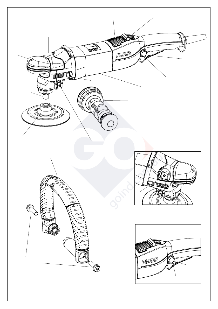
TOOL ASSEMBLY
Position the cap (6) on the gearbox such that the holes for mounting
the screws (5) are aligned with those on the gearbox (8).
Screw the side handle (5). Side handle may be positioned to
the right or to the left of the equipment.
ASSEMBLY / DISASSEMBLY OF ACCESSORIES
ASSEMBLY
PLATE PAD HOLDER
Screw plate pad holder (7) over spindle shaft (4) while
preventing it from moving or stop movement by enabling lock
button (10).
PAD
Apply pressure on polishing pad to join pad to plate.
DISASSEMBLY
PLATE PAD HOLDER
- Lock the spindle by pressing button (10), while at the same
time rotating the pad until it locks position.
- dismount the pad.
Never press the button to lock the pad or pas until the
tool has stopped moving and is perfectly stationary;
the gear box or the push button pin could be broken
and the guarantee would be invalidated.
- PAD
Tear off the worn pad and fit the new pad (see ASSEMBLY).
BEFORE COMMISSIONING
Before putting the machine into operation ensure that:
- the package is intact and there is no sign of damage due to
transport and storage;
- the machine is complete; check the number and the type of
parts to make sure they comply with those in this guide;
- the energy source complies with machine rated features;
- the power cable and its plug are in perfect condition;
- the ON/OFF (2) switch is effective and works with the plug
removed;
- all machine parts are correctly installed and free of damage;
- the ventilation slits (11) are not obstructed.
START AND STOPPING
WARNING: after power cutout, if the ON/OFF switch is
in the ON position, it must be released (see Stop).
LH19E
- Starting: push the lever of the switch (9) towards the body
of the tool; if the tool is to be locked in the ON position,
press button (2) at the same time and keep it pressed while
releasing lever (9), thus locking the switch.
- Stopping: release the lever of the switch or, if locked in
position, push the lever to release the lock button.

9
The tool continues to rotate after some second it is
turned off.
SPEED ADJUSTMENT
The speed can be adjusted in two ways: by means of the
variable actuation switch (2), by means of the adjustment
wheel tted on the upper part of the machine (3)
Adjustment by means of the wheel (3) affects the adjustment
made using the variable actuation switch (9), determining the
maximum speed of the motor.
The speed must be selected according to the characteristics of
the pads and those of the material to be machined.
ALLOWED ACCESSORIES
Polishing foam and foam support pad up to Ø 200 mm max.
NOISE/VIBRATION LEVEL
The equivalent noise pressure level and the mean squared
acceleration are measured according to standard:
EN 60745
SOUND
PRESSURE
LEVEL
[dB(A)]
UNCERTAINTY
[dB(A)]
SOUND
POWER
LEVEL
VIBRATION LEVEL[m/s2]
(polishing)
On 3 AXIS UNCERTAINTY
LpA K LwA ahK
LH19E 85 3 96 2,50 1,00
Use ear protection!
Displayed emission values are comparative and are to
be employed for a provisional assessment of the
operator’s risk exposure during the work period. Appropriate
evaluation of work period must also include tool’s idle and stop
periods. These emission values represent the tool’s main
applications. If the tool is used for other applications, with
other accessories, or if it does not undergo regular
maintenance, emission values can signicantly increase during
operations.
MAINTENANCE
All maintenance operations are carried out with the power
supply disconnected.
At the end of each work session, or when required, remove any
dust from the body of the tool using a jet of compressed air,
paying particular attention to the motor ventilation slots.
No other maintenance operations must be undertaken by
the user.
Maintenance and cleaning of the inner parts, like brushes,
ball bearings, gears etc. or others, must be carried out only
by an authorized customer-service workshop also available
on the website http://www.rupes.it under Service section. Use
exclusively original RUPES. p
DISPOSAL (WEEE DIRECTIVE)
For EU countries only: According to the European
Directive on Waste from electrical and electronic
equipment and its implementation in conformity with
national standards, exhausted electrical equipment must be
collected separately, in order to be recycled in an
environmentally friendly way. The product, when it reaches the
end of its life, must not be dispersed in the environment or
thrown away as household waste. It must be disposed at
authorized recycling centres (contact your local authorities to
know where to dispose of the product according to the law).
The correct disposal of the product contributes to the health
and preservation of the environment.
Illegal disposal of the product will entail penalties against the
offenders.
CONFORMITY DECLARATION
We declare on our responsibility that the represented tool is in
conformity with the Essential Requirements of Safety of the
following Directives:
2006/42/EC; 2014/30/EU; 2011/65/EU.
The tests have been carried out in accordance with the
European Harmonised Standard:
EN 60745-1:2009 + A11:2010
EN 60745-2-3:2011 + A2:2013 + A11:2014 + A12:2014
+ A13:2015
EN 55014-1: 2017
EN 55014-2: 2015
EN 61000-3 -2: 2014
EN 61000-3-3: 2013
EN 62233 : 2008
EN IEC 63000:2018
THE PRESIDENT
G. Valentini
Vermezzo con Zelo (MI), 01/12/2021
Technical file at:
RUPES SpA a socio unico
Via Marconi, 3A - Loc. Vermezzo 20071
VERMEZZO CON ZELO (MI) - Italy
S.p.A a socio unico

88
RUPES S.p.A. a socio unico
Via Marconi, 3A - Loc. Vermezzo 20071
VERMEZZO CON ZELO (MI) - Italy
Tel. +39 02 946941
Fax +39 02 94941040
Uff. Vendite e assistena clienti:
Tel. +39 02 94694312
e-mail: info_rupes@rupes.it
web: http://www.rupes.com
Cod. 9.2756 - Rev 4 - MARZO 2022
Other manuals for LH19E
2
Table of contents
Other Rupes Sander manuals
Popular Sander manuals by other brands

Bosch
Bosch PEX 400 AE Original instructions

Festool
Festool LEX 2 185/7 instruction manual

Ober
Ober MINI 626/SL operating instructions

Alpha tools
Alpha tools BT 450 operating instructions

Powermatic
Powermatic 1632 Operating instructions and parts manual

Powermatic
Powermatic DDS-225 Operating instructions and parts manual