Rupes LH31N Manual

ISTRUZIONI ORIGINALI PER L'USO E LA MANUTENZIONE
ORIGINAL OPERATING AND MAINTENANCE INSTRUCTIONS
NOTICE ORIGINAL D'EMPLOI ET D'ENTRETIEN
ORIGINAL-BEDIENUNGS-UND WARTUNGSANLEITUNG
INSTRUCCIONES ORIGINAL DE USO Y MANUTENCION
AANWIJZINGEN VOOR HET GEBRUIK EN HET
ONDERHOUD ORIGINEEL
ИНСТРУКЦИЯ ПО ЭКСПЛУАТАЦИИ И
ОБСЛУЖИВАНИЮ
1
ОРИГИНАЛЬНЫЙ
Levigatrici angolari
Angular sanders
Ponceuses angulaires
Winkelschleifer
Lijadoras angulares
Haakse slijpmachines
Угловые полировальные машины
LH31N - LH32EN
LH232N
Via Marconi, 3A - 20080 VERMEZZO (Mi) - Italy
Tel. 02/946941 - Fax 02/94941040
e-mail: info_rupes@rupes.it -web: www.rupes.com


3
3
Attenzione pericolo / Avvertenze ISO7010 - W001
Leggere le istruzioni ISO7010 - M002
Indossare gli occhiali protettivi ISO7010 - M004
Indossare le protezioni acustiche ISO7010 - M003
Indossare una maschera ISO7010 - M016
Indossare guanti protettivi ISO7010 - M009
Marcatura di conformità
Marchio di conformità EurAsian
Marchio di Qualità Italiano
Marchio C-Tick
Smaltimento dell’apparecchio dismesso
Freccia Agire in direzione indicata dal senso della freccia
Alcuni dei seguenti simboli possono essere presenti sul vostro utensile. Si prega di studiarli e imparare il loro significato. Una corretta interpretazione permetterà
un utilizzo migliore e sicuro dell’utensile.
ITALIANO
SIMBOLI
ISTRUZIONI ORIGINALI PER L’USO

4
MODELLO LH232N LH31N LH32EN
CLASSE DI ISOLAMENTO II
POTENZA ASSORBITA 1200 W 1200 W 1200 W
PROTEZIONE ELETTRONICA CONTRO I SOVRACCARICHI NO NO SI
REGOLAZIONE ELETTRONICA DELLA VELOCITÀ NO NO SI
GIRI/MINUTO 1600÷3400 3400 1400÷3400
CAMBIO MECCANICO DI VELOCITÀ SI* NO NO
DIAMETRO DEL DISCO ABRASIVO mm 178 178 178
DIAMETRO MAX DEL TAMPONE mm 200 — —
FILETTATURA DELL’ALBERO MANDRINO M14 M14 M14
MASSA Kg 3,7 3,3 3,3
DATI TECNICI ITALIANO
AVVERTENZE GENERALI
Le istruzioni per la sicurezza e la prevenzione degli infortuni sono
riportate nel fascicolo “INDICAZIONI PER LA SICUREZZA” che
costituisce parte integrante della presente documentazione, Il pre-
sente MANUALE D’ISTRUZIONI per l’uso riporta solamente le
informazioni aggiuntive strettamente correlate all’uso specifico della
macchina.
UTILIZZO CONFORME AGLI SCOPI PREVISTI
Questo utensile è destinato a funzionare come lucidatrice. Leggere
tutti gli avvertimenti di sicurezza, le istruzioni, le illustrazioni e le
specifiche forniti con questo utensile. Il mancato rispetto di tutte le istru-
zioni sotto riportate può causare una scossa elettrica, un incendio e/o un
incidente grave.
Le operazioni di molatura, levigatura, spazzolatura metallica o di
taglio non sono consigliate con questo utensile. Le operazioni per le
quali non è previsto l’utensile possono provocare un pericolo e causare
danni alle persone.
Non utilizzare accessori non specificatamente realizzati per l’uso pre-
visto o non consigliati dal produttore. Il semplice fatto che l’accessorio
possa essere fissato al vostro utensile non garantisce un funzionamento
in tutta sicurezza.
La velocità nominale dell’accessorio deve essere almeno pari alla
velocità massima indicata sull’utensile. Gli accessori fatti funzionare a
una velocità superiore a quella nominale possono rompersi ed essere
proiettati in aria.
Il diametro esterno e lo spessore del vostro accessorio devono
essere adatti alle caratteristiche di capacità del vostro utensile. Gli
accessori che hanno dimensioni non corrette non possono essere protetti
o controllati adeguatamente.
La conformazione degli accessori deve adattarsi correttamente al
mandrino dell’utensile. Gli accessori dotati di fori dell’albero che non
corrispondono agli elementi di montaggio sull’utensile non rimarranno in
equilibrio, vibreranno eccessivamente e potranno provocare una perdita
di controllo.
Non usare un accessorio danneggiato. Se l’utensile o l’accessorio ha
subito una caduta, esaminare i danni eventuali o installare un
accessorio non danneggiato. Dopo aver esaminato e installato un
accessorio, mettetevi, insieme alle persone presenti, a una distanza
di sicurezza dall’accessorio rotante e fate funzionare l’utensile alla
velocità massima a vuoto per un minuto. Gli accessori danneggiati si
romperanno in genere in questo periodo di prova.
I valori indicati sono riferiti ad una tensione nominale di 230V/50Hz. In caso di tensioni o frequenze d’alimentazione differenti, i valori pos-
sono variare. Riferirsi all’etichetta dati tecnici per conoscere i valori di targa dell’utensile
II
II
in funzione della EPTA-Procedure 01/2003
(*) La macchina deve funzionare collegata ad un opportuno sistema di aspirazione delle polveri (non fornito)

5
AVVERTENZE DI SICUREZZA SPECIFICHE PER LE OPERAZIONI DI LUCIDATURA
Non permettere ad alcuna parte allentata della cuffia dell’accessorio
di lucidatura ne alle stringhe di fissaggio di girare liberamente.
Mettere in sicurezza o tagliare ogni fili di fissaggio allentato. I fili di
fissaggio allentati e in rotazione possono attorcigliarsi sulle vostre
dita oppure impigliarsi sul pezzo in lavorazione.
PARTI DELLA MACCHINA
1 - Etichetta di identificazione
2 - Leva dell’interruttore
3 - Blocco dell’interruttore
4 - Regolazione elettronica della velocità
5 - Albero mandrino
6 - Impugnatura ausiliaria
7 - Ghiera conica di fissaggio piattello portatampone e disco abrasivo
8 - Piattello portatampone (a richiesta) ( LH232N)
8A - Platorello vulcofix (a richiesta) (LH31N - LH32EN - LH232N)
9 - Chiavi di servizio (da 17 mm e a pioli)
10 - Feritoie per ventilazione motore
MESSA IN FUNZIONE
Prima di mettere in funzione la macchina accertarsi che:
- l’imballo sia integro e non mostri segni di danneggiamento dovuti a
trasporto e magazzinaggio;
- la macchina sia completa; controllare che numero e natura dei
componenti siano conformi a quanto riportato sul presente libretto;
-la fonte di energia e le prese di corrente a disposizione possano
sopportare il carico indicato in tabella e riportato sulla targhetta di
identificazione della macchina il cui facsimile, con spiegazioni, è
riportato a pag. 7.
MONTAGGIO DELLA MACCHINA
Avvitare l'impugnatura (6); queste possono essere posizionate sia a
destra che a sinistra del corpo macchina.
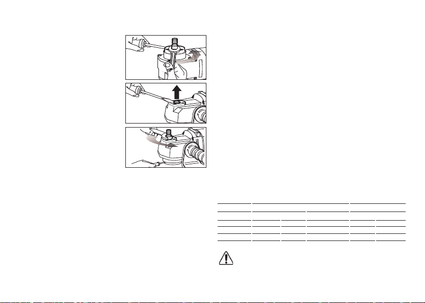
MONTAGGIO DEL PLATORELLO VULCOFIX E DEL PIATTELLO
PORTATAMPONE
Se si opera con le macchine:
1. inserire il platorello vulcofix (8A) sull’albero mandrino (5) (fig. 1);
2. inserire il disco abrasivo;
3. avvitare la ghiera conica (7) e serrare con la chiave a pioli mantenendo
fermo l’albero mandrino con la chiave da 17 mm. (fig. 2).
PRIMA DELLA MESSA IN SERVIZIO
Accertarsi che:
- la fonte di energia sia conforme alle caratteristiche della macchina;
- cavo di alimentazione e relativa spina siano in perfetto stato;
- l'interruttore di inserimento/disinserimento sia efficiente operando però
a spina disinserita;
- tutti i componenti della macchina siano montati correttamente e non
presentino segni di danneggiamento;
- le feritoie di ventilazione non siano ostruite.
AVVIAMENTO E FERMATA
- Avviamento: premere la leva dell'interuttore (2) verso l’alto; qualora se ne
desideri il bloccaggio in posizione "inserito", spingere in avanti il blocco
dell’interruttore (3) verso il corpo della macchina.
- Fermata: rilasciare la leva dell’interruttore (2); qualora l’interruttore è in
posizione “inserito”, premere la leva dell’interruttore (2) verso l’alto in modo
da rilasciare il blocco dell’interruttore (3).
Attenzione: l’utensile continua a ruotare dopo il suo spegnimento.
Attendere che si sia fermato completamente prima di posarlo.
FUNZIONAMENTO DI PROVA
Avviare la macchina e controllare che non siano presenti vibrazioni
anomale o scentrature del piattello o del disco abrasivo.
In caso contrario spegnere la macchina immediatamente e
provvedere ad eliminare le anomalie.
REGOLAZIONE ELETTRONICA DEL NUMERO DI GIRI
(LH32EN)
La regolazione del numero di giri si ottiene manovrando opportuna-
mente la rotella (3). La scelta della velocità va fatta in funzione delle
caratteristiche dei tamponi o dei dischi abrasivi e del materiale da lavorare.

6
UTILIZZAZIONE DEL MODELLO LH232N COME LUCIDATRICE
(1.600 giri/min.)
(A)
- Inserire un cacciavite nell'apposita
sede in modo da bloccare l'albero
mandrino (5);
- svitare con la chiave da 17 mm l'albero
mandrino.
(B)
Rimuovere il tappo (come nella figura B)
ed avvitare nella sede filettata l'albero
precedentemente rimosso dalla sede
inferiore.
(C)
- Inserire un cacciavite nell’apposita
sede in modo da bloccare l’albero;
- serrare l’albero con la chiave da 17 mm.
Potete ora utilizzare l’utensile come
lucidatrice dopo aver montato il piattello
secondo le istruzioni nel libretto.
SMONTAGGIO E SOSTITUZIONE DEI DISCHI ABRASIVI
(LH31N - LH32EN - LH232N)
- Bloccare l’albero mandrino con la chiave da 17 mm;
- svitare la ghiera conica di fissaggio con la chiave a pioli;
- sostituire il disco abrasivo;
- riavvitare la ghiera conica e serrare con la chiave a pioli.
Non sono ammessi altri attrezzi per il serraggio/disserraggio.
UTENSILI DI LAVORO AMMESSI
LH31N - LH32EN - LH232N
Dischi abrasivi da Ø 178 mm.
LH232N
Piattelli portatamponi e tamponi fino a Ø 200 mm.
MANUTENZIONE
Tutte le operazioni vanno eseguite a spina disinserita.
A fine lavoro, od in caso di necessità, spolverare con getto d'aria
compressa il corpo macchina prestando particolare attenzione alla pulizia
delle feritoie di ventilazione del motore.
Non sono ammessi altri interventi da parte dell'utente.
Per la manutenzione e la periodica pulizia delle parti interne, come spaz-
zole, cuscinetti, ingranaggi etc. o altre necessità rivolgersi ai Centri di As-
sistenza autorizzati.
SICUREZZA ELETTRICA - BASSA TENSIONE
Le prove/verifiche sono state eseguite in accordo alle norme:
EN 60745-1 sicurezza degli utensili elettrici a motore portatili
EN 60745-2-3 norme particolari per lucidatrici.
SCHERMATURA CONTRO I RADIODISTURBI
Le macchine sono conformi agli effetti della prevenzione ed eliminazione
dei radiodisturbi misurati secondo le norme EN55014-1+EN55014-2;
EN61000-3-2+EN61000-3-3.
FORMAZIONE DI RUMORE/ VALORE MEDIO DELL'ACCELERAZIONE
Il livello equivalente di pressione sonora (rumorosità) e Il valore
quadratico medio dell'accelerazione è misurati secondo le norme
EN 60745-1.
(A)
(B)
(C)
Livello di Pressione acustica / Potenza sonora Livello di vibrazioni su 3 assi
LPA LWA Incertezza ahIncertezza
dB(A) m/s2
LH31N 81 92 3 2,3 0,5
LH32EN 81 92 3 2,3 0,5
LH232N 85 96 3 2,5 1
Attenzione! i valori di misura indicati sono validi solo per utensili nuovi.
Nell’impiego quotidiano i valori di rumore e vibrazione cambiano.

7
Dichiariamo sotto la nostra responsabilità che l’utensile elettrico a motore portatile, al
quale fa riferimento il presente manuale, è conforme ai Requisiti Essenziali delle Direttive:
Le prove/verifiche sono eseguite in accordo alle seguenti Normative:
Fascicolo tecnico presso:
RUPES S.p.A.
Via Marconi, 3A
20080 VERMEZZO (Mi) - Italy
Vermezzo (MI), 24/01/2018 IL PRESIDENTE
G. Valentini
S.p.A
DICHIARAZIONE DI CONFORMITÀ
2006/42/CE, 2014/35/CE, 2014/30/CE, 2011/65/CE.
EN 60745-1:2009 + A11:2010
EN 60745-2-3:2011 + A2:2013 + A11:2014 + A12:2014 + A13:2015
EN 55014-1:2006 + A1:2009 + A2:2011
EN 55014-2:1997 + A1:2001 + A2:2008
EN 61000-3-2:2014
EN 61000-3-3:2013
EN 62233:2008
EN 50581:2012
SMALTIMENTO
Solo per i Paesi CE: Secondo la Direttiva Europea sui rifiuti di
apparecchiature elettriche ed elettroniche e la sua attuazione in
conformitàdellenormenazionali,le apparecchiatureelettricheesauste
devono essere raccolte separatamente, ai fini di essere riciclate in
modo eco-compatibile. Il prodotto, quando giunge a fine vita, non deve essere
disperso nell’ambiente o gettato tra i rifiuti domestici, ma deve esse smaltito
presso i centri di raccolta differenziata autorizzati (contattare le autorità locali
competenti per conoscere dove smaltire il prodotto secondo le norme di legge).
Il corretto smaltimento del prodotto contribuisce alla tutela della salute e alla
salvaguardia dell’ambiente.
Lo smaltimentoabusivo del prodotto comportasanzioni a carico deitrasgressori.

8
TYPE LH232N LH31N LH32EN
INSULATION CLASS II II II
ABSORBED POWER 1200 W 1200 W 1200 W
ELECTRONIC OVERLOAD PROTECTION NO NO YES
ELECTRONIC SPEED CONTROL NO NO YES
ROTATION RPM 1600÷3400 3400 1400÷3400
MECHANICAL SPEED CONTROL YES* NO NO
ABRASIVE DISC DIAMETER mm 178 178 178
BUFFER DIAMETER MAX mm 200 — —
SPINDLE THREAD M14 M14 M14
WEIGHT Kg 3,7 3,3 3,3
TECHNICAL DATA ENGLISH
GENERAL WARNINGS
The safety and accident prevention instructions are reported in
the “SAFETY INSTRUCTION” booklet which forms an integral part
of these documents. This OPERATING INSTRUCTIONS MANUAL
indicates the additional information required specifically for use
of the tool.
CORRECT USAGE
This tool is designed to be used as a polisher. Read all the
warnings, instructions, indications provided on drawings and
specifications supplied with this tool. Failure to comply with all the
instructions provided below may cause electrical shocks, fires and/or
serious injuries.
This tool is not intended to be used for smoothing, metal
brushing and cutting operations. The use of this tool for unintended
applications may cause hazards and injuries to people.
The tool must be used with accessories that have been
specifically designed or recommended by the manufacturer. The
fixing of the accessory to the tool does not guarantee a safe
operation.
The rated speed of the accessories must be at least equivalent to
the maximum speed specified on the tool. Using the accessories
at speeds above the rated one, may cause them to break or be
projected into the air.
The external diameter and thickness of the accessories must
match the specifications of the tool. Accessories with incorrect
dimensions cannot be adequately protected or controlled.
The configuration of accessories must match the tool. The use of
accessories that cannot be perfectly fitted on the tool may result in
imbalance, excessive vibrations and in the impossibility of controlling
the tool.
Do not use damaged accessories. Before use, inspect all the
accessories. Inspect the supporting pads and verify there are no
cracks, tears or excessive wear. If the tool or accessory has
fallen, verify that it is not damaged or install a new accessory.
After inspecting or installing an accessory, test the operation of
the tool at maximum speed and without load for one minute,
keeping at a safety distance. If the accessories are damaged, they
will break during this test.
8
The values shown are based on a nominal voltage of 230V/50Hz. In the case of voltages and frequencies of different power values may
vary. Refer to the label technical specifications to the nominal values of the tool.
(*) The tool must be connected to a suitable dust extraction system (not supplied).
according to EPTA-Procedure 01/2003

9
SAFETY WARNINGS APPLICABLE TO POLISHING OPERATIONS
Verify that no loosened part of the polishing tool shroud or the
locking ties can rotate freely. Safely position or cut all the loosened
fixing wires. Loosened or revolving fixing wires may twist around the
operator’s fingers or get caught by the work piece being machined.
PARTS OF THE TOOL
1 - Identification plate
2 - Switch lever
3 - Switch block
4 - Electronic rpm regulation
5 - Spindle
6 - Auxiliary handle
7 - Buffer pad and abrasive disc tapered ring nut
8 - Buffer pad (on request) (LH232N)
8A - Vulcofix pad (on request) (LH232N)
9 - Wrenches (17 mm spanner and pin spanner)
10 - Motor ventilation slots
STARTING UP
Before starting-up the tool ensure that:
- the packaging is complete and does not show signs of having been
damaged during storage or transport;
- the tool is complete; check that the number and type of components
comply with that reported in this instruction booklet;
- the power supply and socket outlet can support the load reported in the
table and that indicated on the tool identification plate reproduced and
explained on page 11.
ASSEMBLING THE TOOL
Assemble the handle (6); these can be positioned either on the left or
right of the tool body.
MOUNTING THE VULCOFIX PAD AND BUFFER PAD
If working with machines:
1. Insert the vulcofix pad (8A) on the spindle (5) (fig. 1).
2. Insert the abrasive disc;
3. Screw on the tapered ring nut (7) and tighten it using the pin spanner,
preventing the spindle from moving using the 17 mm. spanner (fig. 2).
BEFORE STARTING THE TOOL
Ensure that:
- the power supply conforms with the characteristics of the tool;
- the power supply cable and plug are in perfect condition;
- the ON/OFF switch works properly though with the power supply
disconnected;
- all the parts of the tool have been assembled in the proper manner and
that there are no signs of damage;
- the ventilation slots are not obstructed.
STARTING AND STOPPING
- Starting:move the switch lever (2) up; to lock it in "engaged" position,
move the switch block (3) forward towards the machine body.
- Stopping: : release the switch lever (2); if the switch is in "engaged"
position, move the switch lever (2) up in order to release the switch
block (3).
Warning! The tool continues to rotate after it is turned off.
Wait until it has come to a full stop before laying it down.
TEST RUN
Start the tool and check that there are no unusual vibration, no
dismatching of the buffer pad or of the abrasive disc.
Otherwise, switch-off the tool immediately and eliminate the cause.
ELECTRONIC SELECTING RPM (LH32EN)
The rpm can be adjusted by rotating the wheel (3). The choice of speed
depends on the characteristics of the abrasive disc and the material to be
worked.

10
USING THE LH232N MODEL AS A POLISHER
(1600 rpm)
(A)
- Insert a screwdriver in the special slot
to lock the spindle (5);
- use the 17 mm spanner to unscrew
the spindle.
(B)
Remove the plug (as in figure B) and
screw the threaded spindle previous
removed from the lower housing in the
seating.
(C)
- Insert a screwdriver in the specific
housing to block the shaft;
- tighten the shaft with the 17 mm wrench.
You can now use the tool as a polisher
after assembling the disk following the
instructions in the booklet.
DISMOUNTING AND REPLACING ABRASIVE DISCS
(LH31N - LH32EN - LH232N)
- Hold the spindle still with the 17 mm. spanner;
- unscrew the tapered ring nut, loosening it with the pin spanner;
- replace the used abrasive disc;
- re-tighten the tapered lock nut and lock it in position using the pin spanner.
The use of any other tool is strictly prohibited.
USABLE WORKING TOOLS
LH31N - LH32EN - LH232N
Ø 178 mm abrasive discs.
LH232N
Buffer pads and buffers up to 200 mm Ø.
MAINTENANCE
All maintenance operations are carried out with the power supply
disconnected.
At the end of each work session, or when required, remove any dust from
the body of the tool using a jet of compressed air, paying particular
attention to the motor ventilation slots.
No other maintenance operations must be undertaken by the user.
Maintenance and cleaning of the inner parts, like brushes, ball
bearings, gears etc. or others, must be carried out only by an
authorised customer-service workshop.
ELECTRIC SAFETY - LOW TENSION
The tests have been carried out in accordance with the standard:
EN 60745-1 safety of hand-held electric motor operated tools
EN 60745-2-3 particular requirements for polishers.
RADIO SUPPRESSION
The tools are suppressed in accordance for the prevention and elimination
of radio disturbances measured in accordance with standard: EN55014-1+
EN55014-2; EN61000-3-2+EN61000-3-3.
NOISE / MEAN ACCELERATION VALUE
The noise level produced and themean quadratic acceleration value are
measured according to regulation
EN 60745-1
Sound pressure level / Sound power level 3 axis vibration level
LPA LWA Uncertainty ahUncertainty
dB(A) m/s2
LH31N 81 92 3 2,3 0,5
LH32EN 81 92 3 2,3 0,5
LH232N 85 96 3 2,5 1
Danger! The indicate measurements refer to new power tools. Daily usa
causes the noise and vibration values to change.

11
We declare on our responsability that the hand-held motor operated tool, which is
mentioned in the present operating manual, is in comformity with the Essential Re-
quirements of Safety of the following Directives:
The tests have been carried out in accordance with following Standards:
Technical file at:
RUPES S.p.A.
Via Marconi, 3A
20080 VERMEZZO (Mi) - Italy
Vermezzo (MI), 24/01/2018
CONFORMITY DECLARATION
IL PRESIDENTE
G. Valentini
S.p.A
2006/42/CE, 2014/35/CE, 2014/30/CE, 2011/65/CE.
EN 60745-1:2009 + A11:2010
EN 60745-2-3:2011 + A2:2013 + A11:2014 + A12:2014 + A13:2015
EN 55014-1:2006 + A1:2009 + A2:2011
EN 55014-2:1997 + A1:2001 + A2:2008
EN 61000-3-2:2014
EN 61000-3-3:2013
EN 62233:2008
EN 50581:2012
DISPOSAL
For EC countries only: According to the European Directive on
Waste from electrical and electronic equipment and its
implementation in conformity with national standards, exhausted
electrical equipment must be collected separately, in order to be
recycled in an environmentally friendly way. The product, when it
reaches the end of its life, must not be dispersed in the environment or
thrown away as household waste. It must be disposed at authorized
recycling centres (contact your local authorities to know where to
dispose of the product according to the law). The correct disposal of the
product contributes to the health and preservation of the environment.
Illegal disposal of the product will entail penalties against the offenders.
Disposing of the product correctly contributes to protecting human
health and safeguarding the environment. Any illegitimate disposal of
the product will be punishable by law.

CARACTERISTIQUES TECHNIQUES FRANÇAIS
TYPE LH232N LH31N LH32EN
CLASSE DE PROTECTION II II II
PUISSANCE ABSORBEE 1200 W 1200 W 1200 W
PROTECTION ELECTRONIQUE CONTRE LES SURCHARGES NON NON OUI
REGLAGE ELECTRONIQUE DE LA VITESSE NON NON OUI
TOURS/min 1600÷3400 3400 1400÷3400
CHANGEMENT MECANIQUE DE VITESSE OUI* NON NON
DIAMETRE DU DISQUE ABRASIF mm 178 178 178
DIAMÈTRE MAX DU TAMPON mm 200 — —
FILETAGE DE L’ARBRE MANDRIN M14 M14 M14
MASSE Kg 3,7 3,3 3,3
RECOMMANDATIONS GENERALES
Les instructions relatives à la sécurité et à la protection contre les
accidents du travail sont contenues dans le fascicule
"INDICATIONS RELATIVES A LA SECURITE" qui fait partie
intégrante de la présente documentation. Le present NOTICE
D'INSTRUCTIONS relatives à l'utilisation indique uniquement les
informations complémentaires qui sont étroitement linées à
l'utilisation spécifique de la machine.
UTILISATION CONFORME
Cet outil est prévu pour fonctionner en tant que lustreuses. Lire
toutes les prescriptions de sécurité, les instructions, les
illustrations et les spécifications fournies avec cet outil. Le non-
respect de toutes les instructions susmentionnées peut provoquer
une décharge, un incendie et/ou un accident grave.
Il est déconseillé d’effectuer des opérations de ponçage,
brossage métallique ou de coupe avec cet outil. Les opérations
pour lesquelles l’outil n’est pas prévu peuvent provoquer un danger
et causer des blessures aux personnes.
Ne pas utiliser les accessoires qui ne sont pas spécialement
conseillés par le producteur. Le simple fait que l’accessoire puisse
être fixé sur votre outil ne garantit pas un fonctionnement en toute
sécurité.
La vitesse nominale de l’accessoire doit être au moins égale à la
vitesse maximale indiquée sur l'outil. Les accessoires que l’on
utilise à une vitesse supérieure à la vitesse nominale peuvent se
casser et être projetés en l’air.
Le diamètre extérieur et l’épaisseur de votre accessoire doivent
être adaptés aux caractéristiques de capacité de votre outil. Il est
impossible de protéger ou de contrôler de façon appropriée les
accessoires présentant des dimensions non correctes.
La conformation des accessoires doit s’adapter correctement au
mandrin de l’outil. Les accessoires munis de trous de l’arbre qui ne
correspondent pas aux éléments de montage sur l’outil ne resteront
pas en équilibre, ils vibreront excessivement et pourront provoquer
une perte de contrôle.
Ne pas utiliser un accessoire endommagé. Avant toute utilisation,
examiner les accessoires. Si l’outil ou l’accessoire est tombé,
examiner les éventuels dégâts ou installer un accessoire non
endommagé. Après avoir examiné et installé un accessoire,
placez-vous, ainsi que les personnes présentes, à une certaine
distance de securite de l’accessoire tournant et faites fonctionner
l’outil à la vitesse maximale à vide pendant une minute. Les
accessoires endommagés se casseront en général durant cette
période d’essai.
12
Les valeurs indiquées sont basées sur une tension nominale de 230V/50Hz. Dans le cas des tensions et des fréquences de différentes valeurs
de la puissance peut varier. Reportez-vous aux spécifications techniques d'étiquettes pour les valeurs nominales de l'outil.
suivant EPTA-Procédure 01/2003
(*) La machine doit fonctionner reliée à un système d’aspiration approprié des poussières (non fourni).

13
CONSIGNES DE SECURITE SPECIFIQUES POUR LES OPERATIONS DE
LUSTRAGE
Ne permettre à aucune partie desserrée de la protection de l'accessoire
de lustrage ni aux lacets de fixation de tourner librement. Sécuriser ou
couper tout fil de fixation desserré. Les fils de fixation desserrés et en ro-
tation peuvent s'entortiller autour de vos doigts ou s'entraver sur la pièce
travaillée.
PARTIES DE LA MACHINE
1 - Etiquette d'identification
2 - Levier de l’interrupteur
3 - Verrouillage de l’interrupteur
4-Réglage électronique de la vitesse
5 - Arbre mandrin
6 - Poignée auxiliaire
7 - Collier conique de fixation plateau porte-tampon et disque abrasif
8 - Plateau porte-tampon (à la demande) ( LH232N)
8A - Plateau vulcofix (à la demande) (LH31N - LH32EN - LH232N)
9 - Clès de service (17 mm á echelons)
10 - Fentes pour ventilation moteur
MISE EN SERVICE
Avant de mettre la machine en service, s'assurer que:
- l'emballage est intègre et qu'il ne montre aucun signe d'endommage-
ments dus au transp ort et au stockage;
- la machine est complète; s'assurer que le nombre et la nature des compo-
sants sont conformes aux indications contenues dans le présent livret d'in-
structions;
- la source d'énergie et les prises de courant à disposition peuvent supporter
la charge indiquée dans le tableau et sur la plaquette d'identification de la
machine, dont le fac-similé et les explications relatives sont fournis page 15.
MONTAGE DE LA MACHINE
Visser la poignée (6); ce peut etre mise à droite
machine.
MONTAGE DU PLATEAU VULCOFIX ET DU PLATEAU PORTE-TAMPON
Si on opère avec les machines:
1. Mettre le plateau vulcofix (8A) sur l’arbre mandrin (5) (fig. 1);
2. mettre le disque abrasif;
3. visser le collier conique (7) et serrer à l’aide de la clé à tétonsen immobili-
sant l’arbre mandrin à l’aide de la clé de 17 mm (fig. 2).
AVANT LA MISE EN SERVICE
S'assurer que:
- la source d'énergie est conforme aux caractéristiques de la machine;
- le câble d'alimentation et la fiche relative sont en parfait état;
- l'interrupteur de mise en marche/arrêt est efficace en agissant cependant
lorsque la fiche est débranchée;
- tous les composants de la machine sont montés correctement et ne
présentent pas de signes d'endommagement;
- les fentes de ventililation ne sont pas bouchées.
MISE EN MARCHE ET ARRET
- Mise en marche: appuyer sur le levier de l’interrupteur (2) vers le haut ; si l’on
souhaite qu’il se bloque dans la position « enclenché », pousser vers l’avant
le verrouillage de l’interrupteur (3) vers le corps de la machine.
-Arrêt: relâcher le levier de l’interrupteur (2) ; si l’interrupteur est en position «
enclenché », appuyer sur le levier de l’interrupteur (2) vers le haut de manière
à relâcher le verrouillage de l’interrupteur (3).
Attention ! L'outil continue de tourner même après l'arrêt.
Attendre l'arrêt complet avant de la poser.
FONCTIONNEMENT D'ESSAI
Mettre la machine en marche et s'assurer que le plateau ou le disque abrasif
ne vibre pas ou n'est pas décentré.
Dans le cas contraire, débrancher immediatement et éliminer les
anomalies.
REGLAGE ÉLECTRONIQUE DU NOMBRE DE TOURS (LH32EN)
Le réglage du nombre de tours s'obtient en manoeuvrant de manière
appropriée le bouton (3) situé sur la partie arrière de la machine.
Le choix de la vitesse doit être fait en fonction des caractèristiques des disques
abrasif et du matériau à usiner.
ou à gauche du corps de la

14
UTILISATION DU MODELE LH232N COMME POLISSEUSE
(1600 TOURS/MIN)
(A)
- Introduire un tournevis dans le siège
prévu à cet ellet de façon à bloquer
l'arbre mandrin (5);
- à l'aide de la clé de 17 mm, dévisser
l'arbre mandrin.
(B)
Retirer le bouchon (comme dans la
figure B) et visser l'arbre auparavant
retiré du siége inférieur dans le siège
filetè.
(C)
- Introduire un tournevis dans le site prévu
à cet effet de manière à bloquer l'arbre.
- serrer l'arbre avec la clé de 17 mm.
Vous pouvez utiliser l'outil comme
ponceuse après avoir monté le plateau
selon les instructions fournies dans le
manuel.
DEMONTAGE ET REMPLACEMENT DES DISQUES ABRASIFS
(LH31N - LH32EN - LH232N)
- Bloquer l’arbre mandrin à l’aide de la clé de 17 mm;
- dévisser, en débloquant avec la clé à tétons, le collier conique de fixation;
- remplacer le disque abrasif;
- revisser le collier conique et serrer à l’aide de la clé à tétons.
Aucun autre outil n’est admis pour le serrage / desserrage.
OUTILS DE TRAVAIL ADMIS
LH31N - LH32EN - LH232N
Disques abrasifs de Ø 178 mm.
LH232N
Plateaux porte-tampons et tampons jusqu'à 200 mm de diamètre.
ENTRETIEN
Toutes les opérations doivent être effectuées la fiche étant débranchée.
A la fin du travai et en cas de nécessité, dépoussiérer le corps de la ma-
chine à l'aide d'un jet d'air comprimé en accordant une attention particu-
lière au nettoyage des fentes de ventilation du moteur.
Aucune autre intervention de l'utilisateur n'est pas admise.
Tous les travaux d’entretien et les travaux de polissage des piéces inter-
nes, comme les brosses, coussinet, engrenages etc., doivent être effe-
cuès par un atelier de réparation autorisè.
SECURITE ELECTRIQUE - BASSE TENSION
Les proves/verifies out eté executés en accord a les normes:
EN 60745-1 securité des outils électrique a moteur portatives
EN 60745-2-3 règles particuliers puor lustreuses.
PROTECTION CONTRE LES PARASITES RADIO
Les machines sont conformes à les effets de la prévention et des parasi-
tes radio mesures en accord a les normes EN55014-1+EN55014-2;
EN61000-3-2+EN61000-3-3.
FORMATION DU BRUIT / VALEUR MOYENNE DE L'ACCELERATION
Le niveau équivalent de la pression sonore (niveau de bruit) e la
valeur quadratique moyenne de l'accèlérationest est mesurés
conformément aux normes EN 60745-1.
Niveau de pression acoustique / Niveau de puissance acoustique Niveau des vibration selon 3 axies
LPA LWA Incertitude ahIncertitude
dB(A) m/s2
LH31N 81 92 3 2,3 0,5
LH32EN 81 92 3 2,3 0,5
LH232N 85 96 3 2,5 1
Attention! Les valeurs de mesure indiquées s’appliquent aux appareils
neufs. Pendant le mise en ceuvre quotidienne, les valeurs de bruit et de
vibrations varient.

15
Nous déclarons sous notre responsabilité que l’outil électrique à moteur portable, au-
quel se réfère le présent manuel, est conforme aux Conditions Essentielles des Directi-
ves :
Les proves/vérifiés out été exécutés en accord a les vigueurs Régles Harmonisés Eu-
ropéennes Basse Tension:
Dossier technique auprès de:
RUPES S.p.A.
Via Marconi, 3A
20080 VERMEZZO (Mi) - Italy
Vermezzo (MI), 24/01/2018
DÉCLARATION DE CONFORMITÉ
IL PRESIDENTE
G. Valentini
S.p.A
2006/42/CE, 2014/35/CE, 2014/30/CE, 2011/65/CE.
EN 60745-1:2009 + A11:2010
EN 60745-2-3:2011 + A2:2013 + A11:2014 + A12:2014 + A13:2015
EN 55014-1:2006 + A1:2009 + A2:2011
EN 55014-2:1997 + A1:2001 + A2:2008
EN 61000-3-2:2014
EN 61000-3-3:2013
EN 62233:2008
EN 50581:2012
ÉLIMINATION
Uniquement pour les pays de l’UE: Conformément à la directive
européenne relative aux déchets d’équipements électriques et
électroniques et son application selon les normes nationales, les
équipements électriques usagés doivent être collectés séparément
afin d’être recyclés de manière écologiquement responsable.
Le produit, lorsqu’il atteint sa fin de vie, ne doit pas être dispersé dans
l’environnement ou jeté avec les déchets ménagers, mais doit être collecté
dans un centre de tri sélectif afin d’être éliminé (Veuillez contacter les
autorités locales pour obtenir les centres de tri conformes à la législation).
L’élimination correcte du produit contribue à la protection de la santé et de
l’environnement. Des sanctions contre les personnes ne respectant pas
l’élimination correcte du produit seront prises.
L’élimination correcte du produit contribue à la protection de la santé et
de l’environnement. En n’éliminant pas le produit conformément à la loi en
vigueur vous vous exposez à des sanctions.

TYP LH232N LH31N LH32EN
SCHUTZKLASSE II II II
LEISTUNGAUFNAHME 1200 W 1200 W 1200 W
ELEKTRONISCHE ÜBERLASTSCHUTZ NEIN NEIN JA
ELEKTRONISCHE DREHZAHLREGELUNG NEIN NEIN JA
UMDREHUNGEN/MINUTE 1600-3400 3400 1400-3400
MECHANISCHE DREHZAHLANDERUNG JA* NEIN NEIN
DURCHMESSER SCHLEIFSCHEIBEN mm 178 178 178
MAX DURCHMESSER PUFFER mm 200 — —
WELLENGEWINDE M14 M14 M14
GEWICHT Kg 3,7 3,3 3,3
TECHNISCHE DATEN DEUTSCH
ALLGEMEINE HINWEISE
Die Sicherheits-und Unfallverhütungsvorschriften sind im
beiliegenden Heft „HINWEISE ZUR SICHERHEIT" enthalten. Das Heft
ist integrierender Bestandteil der vorliegenden Dokumentation;
Diese BEDIENUNGSANLEITUNG enthält daher nur
Zusatzinformationen, welche den spezifischen Einsatz dieses Geräts
betreffen.
BESTIMMNGSGEMÄßE VERWENDUNG
Dieses Werkzeug ist für den Einsatz als Poliermaschine bestimmt.
Alle Sicherheitshinweise, die Anweisungen, die Abbildungen und die
technischen Daten beachten, die mit diesem Werkzeug geliefert
werden. Die Nichtbeachtung aller unten aufgeführten Anweisungen kann
einen elektrischen Schlag, Brand und/oder schweren Unfall verursachen.
Von Vorgängen des Feinschleifens, Schleifens, metallischen
Bürstens oder Schneidens wird mit diesem Werkzeug abgeraten. Die
Vorgänge, für die der Einsatz des Werkzeugs nicht vorgesehen ist,
können zu Gefahren führen und Personenschäden verursachen.
Kein nicht spezifisch für den vorgesehenen Einsatz hergestelltes
oder nicht vom Hersteller empfohlenes Zubehör verwenden. Die
bloße Tatsache, dass das Zubehörteil auf Ihrem Werkzeug befestigt
werden kann, garantiert keinen vollkommen sicheren Betrieb.
Die Nenngeschwindigkeit des Zubehörs muss mindestens der auf
dem Werkzeug angegebenen Höchstgeschwindigkeit entsprechen.
Zubehör, das bei einer höheren Geschwindigkeit als der
Nenngeschwindigkeit betrieben wird, kann brechen und in die Luft
geschleudert werden.
Der Außendurchmesser und die Stärke Ihres Zubehörs müssen sich
für die Charakteristiken Ihres Werkzeugs eignen. Zubehör mit nicht
korrekten Abmessungen kann nicht angemessen geschützt oder
kontrolliert werden. Die Beschaffenheit des Zubehörs muss sich
korrekt an das Spannfutter des Werkzeugs anpassen. Zubehör mit
Bohrungen der Welle, die nicht mit den Montageelementen auf dem
Werkzeug übereinstimmen, bleiben nicht im Gleichgewicht, vibrieren
zu stark und können zu einem Kontrollverlust führen. Kein
beschädigtes Zubehör verwenden. Ist das Werkzeug oder das
Zubehör heruntergefallen, auf eventuelle Schäden untersuchen oder
nicht beschädigtes Zubehör installieren. Nachdem ein
Zubehörartikel untersucht und installiert wurde, begeben Sie sich
gemeinsam mit den anwesenden Personen in einen
Sicherheitsabstand von dem rotierenden Zubehörartikel und lassen
Sie das Werkzeug bei Höchstgeschwindigkeit eine Minute lang leer
laufen. Beschädigtes Zubehör bricht im Allgemeinen während dieses
Probezeitraums.
16
Die dargestellten Werte basieren auf einer Nennspannung von 230V/50Hz basiert. Im Falle von Spannungen und Frequenzen von verschiede-
nen Leistungswerten kann variieren. Beziehen sich auf die technischen Spezifikationen Label auf die Nennwerte des Werkzeugs.
entsprechend EPTA-Procedure 01/2003
(*) Die genannten Gerätes dürfen nur zusammen mit einer passenden Staubabsaugung betrieben werden für Staub (kein Lieferbestandteil).

17
SPEZIFISCHE SICHERHEITSHINWEISE FÜR DIE POLIERVORGÄNGE
Weder gelösten Teilen der Haube des Polierwerkzeugs noch den Bindern
gestatten, frei zu drehen. Jegliche gelösten Binder sichern oder absch-
neiden. Die gelösten und rotierenden Binder können sich um Ihre Finger
wickeln oder auf dem bearbeiteten Teil verfangen.
BAUTEILE DER MASCHINE
1 - Schild mit Geräte-Kenndaten
2 - Hebel des Schalters
3 - Sperre des Schalters
4 - Elektronische Drehzahlregelung
5-Spindel
6 - Seitlichen-Handgriff
7 - Konische Spannmutter Stutzscheibe und Schleifscheiben
8 - Stutzscheibe (auf Anfrage) (LH232N)
8A - Schleifteller vulkofix (auf Anfrage) (LH31N - LH32EN - LH232N)
9 - Service-Schlüssel (17 mm und Spannmutterschlüssel)
10 - Schlitze zur Motorkühlung
INBETRIEBNAHME
Vor einer Inbetriebnahme des Gerätes sollten Sie sicherstellen:
- daß die Verpackung unversehrt ist und keine Beschädigungen durch
Transport bzw. Lagerung aufweist;
- daß das Gerät vollständig ist, also Anzahl und Art der Geräte-
komponenten mit den Angaben in dieser Gebrauchsanleitung überein
stimmen;
- daß Stromnetz und Steckdosen für die in der Tabelle bzw. auf dem
Geräteschild (vgl. Abbildung u. Beschreibung des Gerateschilds auf Seite
19) genannte Stromlast ausgelegt sind.
ZUSAMMENBAU DER MASCHINE
Den Seitliechen (6); er Kann wahlweise an die linke oder
Gehäuses angesetzt werden.
MONTAGE DER SCHLEFTELLER VULCOFIX UND DER STUTZSCHEIBE
Wenn die Maschinen betrieben werden:
1. Schlefteller Vulcofix (8A) auf Welle des Spanndorns stecken (5) (fig. 1).
2. Stecken schleifscheibe;
3. Die konische Spannmutter (7) festschrauben und dann mit dem Inbus-
schlüssel festziehen, dazu die Spindel mit dem 17 mm (fig. 2).
VOR DER INBETRIEBNAHME
Stellen Sie folgende Punkte sicher:
- das Stromntez entspricht den Gerätekenndaten;
- Anschlußkabel und-Stecker sind in ordnungemäßem Zustand;
- der EIN/AUS- Schalter funktioniert einwandfrei. Allerdings bei gezogenem
Netzstecker;
- Sämtliche Gerätekomponenten sind ordnungsgemäß montiert und zeigen
keine Anzeichen von Beschädigung;
- die Lüftungsschlitze sind nicht verstopft.
EIN-UND AUSSCHALTEN
- Einschalten: Den Hebel des Schalters (2) nach oben stellen. Wenn die
Feststelltaste eingesetzt werden soll, die Sperre des Schalters (3) in Richtung
Maschinenkörper drücken.
- Ausschalten: Den Hebel des Schalters (2) frei geben. Wenn der Schalter
festgestellt ist, den Hebel des Schalters (2) so nach oben drücken, dass die
Sperre des Schalters (3) gelöst wird.
Achtung! Das Werkzeug dreht sich nach dem Ausschalten noch weiter.
Warten, bis es vollständig zum Stillstand gekommen ist, bevor es abge-
stellt wird.
TESTLAUF
Die Maschine starten und sicherstellen, dass die Maschine nicht abnormal
vibriert und dass die Stutzscheibe bzw. die Schleifscheibe zentriert ist.
Andernfalls das Gerät sofort ausschalten und die Störung beheben.
ELEKTRONISCHER DREHZAHLREGLER (LH32EN)
Die Drehzahl stellt man über das Rädchen (3) im hinteren Abschnitt des
Gerätes ein. Die Drehzahl ist passend zum Schleifscheibentyp sowie den
Eigenschaften des zu bearbeitenden Materials zu wählen.
rechte Seite des

18
GEBRAUCH DES MODELLS LH232N ALS POLIERMASCHINE (1.600 U/min)
(A)
- Einen Schraubendreher in die
entsprechende Vertiefung einsetzen
und die Spindelwelle (9) damit
blockieren;
- die Spindelwelle mit dem 17 mm
Schlüssel abschrauben.
(B)
Den Verschlußstopfon
(wie in Abbildung B) entfernen und die
zuvor an der unteren. Position
abgenommene Spindelwelle in den
Gewindesitz einschrauben.
(C)
- Schraubenzieher in den entsprechenden
Sitz einführen, um die Welle zu blockieren;
- Welle mit einem 17 mm Schlüssel
festspannen.
Nachdem die Scheibe entsprechend den
Anweisungen in der Gebrauch-sanleitung
montiert worden sind, kann das Werkzeug
jetzt als Schleif-maschine eingesetzt werden.
ABBAUEN UND AUSTAUSCHEN DER SCHLEIFSCHEIBEN
(LH31N - LH32EN - LH232N)
- Die Welle mit dem 17 mm-Schlüssel kontern;
- die konische Spannmutter mit dem Inbusschlüssel losdrehen;
- die Schleifscheibe ersetzen;
- die konische Mutter wieder aufschrauben und mit dem Inbusschlüssel festziehen.
Die Verwendung sonstiger Werkzeuge zum Festziehen/Lösen ist nicht
zulässig.
ZULASSIGE WERKZEUGE
LH31N - LH32EN - LH232N
Schleifscheiben mit Ø 178 mm.
LH232N
Stutzscheibe und Polierschwamm bis zu 200 mm Ø.
PFLEGE DES GERATES
Sämtliche Reinigungsarbeiten nur bei gezogenem Netzstecker vornehmen.
Reinigen Sie das Gerät nach der Arbeit sowie bei Bedarf mit einem Druck-
luftstrahl. Achten Sie besonders darauf, daß die Lüftungsschlitze des Mo-
tors immer sauber sind.
Sonstige Eingriffe durch den Gerätebenutzer sind nicht zulässig.
Für die Wartung und die periodische Reinigung von den inneren Teilen z.
B: Bürsten, Lagern, Zahnrädern usw. oder andere Bedürfnisse wenden
Sie sich bitte an einer autorisierten Kundendienststelle an.
ELEKTRISCHE SICHERHEIT - NIEDERSPANNUNG
Die Tests wurden nach den Anforderungen der zur Zeit gültigen Normen
ausgeführt:
EN 60745-1 sicherheit für tragbare elektrisch betriebe Maschinen
EN 60745-2-3 besondere Anforderungen für poliermaschine.
FUNKENTSTÖRUNG
Die Geräte erfüllen die Vorschriften der EG-Richtlinie 89/336 zur Vorbeugung
und Beseitigung von Funkstörungen Messung nach Norm EN55014-1+
EN55014-2; EN61000-3-2+EN61000-3-3.
SCHALLPEGEL / MITTLERE BESCHLEUNIGUNG
Der Schalldruckpegel (Geräuschentwicklung) und die mittlere
quadratische Beschleunigungder Maschine, gemessen gemäß UNI EN
ISO 15744 - EN ISO 28927.
Schalldruckpegel / Schalleistungspegel 3-Achsen Vibrationspegel
LPA LWA
Messunsicherheit
ah
Messunsicherheit
dB(A) m/s2
LH31N 81 92 3 2,3 0,5
LH32EN 81 92 3 2,3 0,5
LH232N 85 96 3 2,5 1
Achtung! Di angegebenen Messwerte gelten für neue Geräte. Im
täglichen Einsatz verändern sich Geräusch-und chwingungswerte.

19
IL PRESIDENTE
G. Valentini
S.p.A
ENTSORGUNG
Nur für EU-Länder: Gemäß der Europäischen Richtlinie über die
elektrischen und elektronischen Geräte und deren Umsetzung in
Konformität der nationalen Normen ist Elektroschrott separat zu
sammeln, damit er auf umweltfreundliche Weise wiederverwertet
werden kann. Wenn das Produkt das Ende seiner Lebensdauer
erreicht hat, darf es nicht in der Umwelt freigesetzt oder zusammen mit dem
Hausmüll weggeworfen werden, sondern muss bei autorisierten Recycling-
Sammelzentren entsorgt werden (kontaktieren Sie die kompetenten örtlichen
Behörden, um zu erfahren, wo das Produkt laut Gesetz zu entsorgen ist). Die
korrekte Entsorgung des Produkts trägt zum Schutz der Gesundheit und der
Erhaltung der Umwelt bei. Eine illegale Entsorgung des Produkts hat
Strafmaßnahmen zu Lasten des Gesetzesübertreters zur Folge. Die korrekte
Entsorgung des Produkts trägt zum Schutz der Gesundheit und der Umwelt
bei. Die missbräuchliche Entsorgung des Produkts zieht Sanktionen zu
Lasten des Verursachers nach sich.
KONFORMITÄTSERKLÄRUNG
Wir bestätigen in unserer Verantwortung das die Handgehaltenen
Motorwerkzeuge, die in diesem Betriebshandbuch beschrieben werden, ist
in Übereinstimmung mit den wesentlichen Bestimmungen für die Sicherheit
der folgenden Direktiven:
2006/42/CE, 2014/35/CE, 2014/30/CE, 2011/65/CE.
Die Tests wurden ausgeführt nach den Anforderungen der zur Zeit gültigen
europäischen Harmonisierungsregeln
Niederspannung:
EN 60745-1:2009 + A11:2010
EN 60745-2-3:2011 + A2:2013 + A11:2014 + A12:2014 + A13:2015
EN 55014-1: 2006 + A1: 2009 + A2: 2011
EN 55014-2:1997 + A1: 2001 + A2: 2008
EN 61000-3-2: 2014
EN 61000-3-3: 2013
EN 62233: 2008
EN 50581:2012
Technische Unterlagen bei:
RUPES S.p.A.
Via Marconi, 3A
20080 VERMEZZO (Mi) - Italy
Vermezzo (M), 24/01/2018

DATOS TECNICOS ESPAÑOL
TIPO LH232N LH31N LH32EN
CLASE DE AISLAMIENTO II II II
POTENCIA ABSORBIDA 1200 W 1200 W 1200 W
PROTECCION ELECTRONICA CONTRA LAS SOBRECARGAS NO NO SI
REGULACION ELECTRONICA DE LA VELOCIDAD NO NO SI
REVOLUCIONES/min (r.p.m.) 1600-3400 3400 1400-3400
CAMBIO MECANICO DE VELOCIDAD SI* NO NO
DIAMETRO DEL DISCO ABRASIVO mm 178 178 178
DIAMETRO MAX DEL TAMPON mm 200 — —
ROSCADO DEL ARBOL MANDRIL M14 M14 M14
MASA Kg 3,7 3,3 3,3
ADVERTENCIAS GENERALES
Las instrucciones para la seguridad y la prevención de accidentes se
ilustran en el opúsculo "INDICACIONES PARA LA SEGURIDAD" que
forma parte de la presente documentación. El MANUAL DE
INSTRUCCIONES para el uso ilustra solamente aquellas
informaciones adicionales estrictamente relacionadas con el uso
especifico de la herramienta.
USO CONFORME A LO DETERMINADO
Esta herramienta está destinada a funcionar como pulidora. Leer
todas las advertencias de seguridad, las instrucciones, las
ilustraciones y las especificaciones suministradas con esta
herramienta. El incumplimiento de las instrucciones puede causar
descargas eléctricas, incendios y/o accidentes graves.
Se recomienda no ejecutar con esta herramienta operaciones de
lijado, acepilladura metálica o corte. El empleo de la herramienta en
operaciones para las cuales la herramienta no está diseñada puede
causar peligros y daños a las personas.
No utilizar accesorios no expresamente y recomendados por el
fabricante. El hecho de que el accesorio se pueda fijar en la herramienta
no garantiza un funcionamiento totalmente seguro.
La velocidad nominal del accesorio debe ser al menos igual a la
velocidad máxima indicada en la herramienta. Los accesorios que se
hagan funcionar a una velocidad superior a la nominal se pueden romper
y saltar por el aire.
Las características de su accesorio deben responder a las
características de su herramienta. Los accesorios de dimensiones no
correctas no se pueden proteger y controlar adecuadamente.
La conformación de los accesorios debe adaptarse correctamente al
mandril de la herramienta. Los accesorios cuyos orificios en el eje no
correspondan a los elementos de montaje en la herramienta no
permanecerán en equilibrio, vibrarán excesivamente y podrán provocar
una pérdida de control.
No utilizar accesorios dañados. Antes de cada uso, examinar los
accesorios. Si la herramienta o el accesorio ha sufrido una caída,
verificar si hay daños o instalar un accesorio no dañado. Una vez
examinado e instalado un accesorio, alejarse del plano del accesorio
giratorio, al igual que todas las otras personas presentes, y hacer
funcionar la herramienta eléctrica a la velocidad máxima en vacío
durante un minuto. Los accesorios dañados generalmente se rompen
durante el período de prueba.
20
Los valores mostrados se basan en una tensión nominal de 230V/50Hz. En el caso de tensiones y frecuencias de los valores de poten-
cia diferentes puede variar. Consulte las especificaciones de la etiqueta técnica a los valores nominales de la herramienta.
según EPTA-Procedure 01/2003
(*) La máquina debe funcionar conectada con un adecuado sistema de aspiración del polvo (no suministrado).
Other manuals for LH31N
1
This manual suits for next models
2
Table of contents
Languages:
Other Rupes Sander manuals
Popular Sander manuals by other brands

Parkside
Parkside PTSG 140 A1 Translation of the original instructions

Makita
Makita PV301D instruction manual

Cocraft
Cocraft HP 110 Original instructions

Makita
Makita BO3700 instruction manual

Titan
Titan TTB288SDR Safety and operating manual

Parkside
Parkside PMS 160 A1 Translation of the original instructions