Rupes RE21ACM Wiring diagram

RE21ACM - RS21A - RE21ALN
Levigatrici orbitali pneumatiche con aspirazione
Orbital pneumatic sanders with dust extraction
Ponceuses orbitales pneumatiques avec aspiration
Pneumatische Schwingschleifer mit Staubabsaugung
Lijadoras orbitales neumáticas con aspiración
Pneumatisch vlak schuurmachine met stofafzuiging
Пневматические вращательно-орбитальные
шлифовальные машины с пылеудалением
ISTRUZIONI ORIGINALI PER L'USO
TRANSLATION OF ORIGINAL OPERATING INSTRUCTIONS
CONVERSION DES INSTRUCTIONS DE FONCTIONNEMENT ORIGINAL
ÜBERSETZUNG DES URSPRÜNGLICHEN BEDIENUNGSANLEITUNG
TRADUCCIÓN DE MANUAL DE INSTRUCCIONES ORIGINAL
VERTALING VAN ORIGINELE GEBRUIKSAANWIJZING
ПЕРЕВОД ИНСТРУКЦИИ ПО ЭКСПЛУАТАЦИИ
Via Marconi, 3A - 20080 VERMEZZO (Mi) - ItalyTel. 02/946941 - Fax 02/94941040
9.2180 RE21A_ott2015:libretto RA90A-RA125A-RA150A OK.qxd 15/05/2017 11.49 Pagina 1

MAX OFF
MAX OFF
VACUUM
SYSTEM
6
1
2
3
6
5
8
9
4
1
2
3
6
5
8
9
4
7
10
7
RS21A RE21ACM
1
2
3
6
5
8
4
7
RE21ALN
9
9.2180 RE21A_ott2015:libretto RA90A-RA125A-RA150A OK.qxd 15/05/2017 11.49 Pagina 2

4
8
12
16
20
24
28
ISTRUZIONI ORIGINALI PER L'USO
TRANSLATION OF ORIGINAL OPERATING INSTRUCTION
CONVERSION DES INSTRUCTIONS DE FONCTIONNEMENT ORIGINAL
ÜBERSETZUNG DES URSPRÜNGLICHEN BEDIENUNGSANLEITUNG
TRADUCCIÓN DE MANUAL DE INSTRUCCIONES
VERTALING VAN ORIGINELE GEBRUIKSAANWIJZING
ПЕРЕВОД ИНСТРУКЦИИ ПО ЭКСПЛУАТАЦИИ
9.2180 RE21A_ott2015:libretto RA90A-RA125A-RA150A OK.qxd 15/05/2017 11.50 Pagina 3

DATI TECNICI
MODELLO
PRESSIONE DI ESERCIZIO bar/PSI
CONSUMO ARIA l/min
REGOLAZIONE DELLA VELOCITÀ
GIRI/min
Ø DIAMETRO ORBITA mm
FORMA PIASTRA
DIMENSIONI PIASTRA mm
PIASTRA GOMMA FORATA VELCRATA
SISTEMA D’ASPIRAZIONE
MASSA Kg
ITALIANO ISTRUZIONI ORIGINALI PER L’USO 4
Attenzione pericolo / Avvertenze ISO7010 - W001
Leggere le istruzioni ISO7010 - M002
Indossare gli occhiali protettivi ISO7010 - M004
Indossare le protezioni acustiche ISO7010 - M003
Indossare una maschera ISO7010 - M016
Indossare guanti protettivi ISO7010 - M009
Marcatura di conformità
Marchio di conformità EurAsian
Freccia Agire in direzione indicata dal senso della freccia
SIMBOLI
Alcuni dei seguenti simboli possono essere presenti sul vostro utensile. Si prega di studiarli e imparare il loro significato. Una corretta
interpretazione permetterà un utilizzo migliore e sicuro dell’utensile.
RE21ACM
6.2/90
380
SI
0 ÷ 11.000
3
RETTANGOLARE
80x130
SI
CENTRALIZZATO
0,870
RS21A
6.2/90
380
SI
0 ÷ 11.000
3
DELTA
-
SI
CENTRALIZZATO
0,850
RE21ALN
6.2/90
380
SI
0 ÷ 11.000
3
RETTANGOLARE
70x198
SI
CENTRALIZZATO
0,900
(*) La macchina deve funzionare collegata ad un opportuno sistema di aspirazione delle polveri (non fornito)
9.2180 RE21A_ott2015:libretto RA90A-RA125A-RA150A OK.qxd 15/05/2017 11.50 Pagina 4

5
AVVERTENZE GENERALI
La macchina deve funzionare collegata ad un opportuno sistema di
aspirazione (non fornito).
NORME PER LA SICUREZZA E LA PREVENZIONE DEGLI INFORTUNI
Le istruzioni per la sicurezza e la prevenzione degli infortuni sono
riportate nel fascicolo “INDICAZIONI PER LA SICUREZZA” che
costituisce parte integrante della presente documentazione; il libretto
d’istruzioni per l’uso riporta solamente le informazioni aggiuntive
strettamente correlate all’uso specifico della macchina.
Non fare funzionare mai gli utensili senza i dispositivi di protezione
montati.
Ogni operazione sulla macchina venga eseguita a macchina
scollegata.
Prima dell'azionamento la macchina sia saldamente impugnata e non
sia a contatto con la superficie di lavoro.
Se durante la levigatura si formano polveri nocive alla salute,
l’apparecchio deve essere collegato ad un adatto dispositivo di
aspirazione (non fornito) e devono essere rispettate le norme di
sicurezza valide per il materiale sottoposto a lavorazione.
A causa dei rischi che possono insorgere durante la levigatura, si
raccomanda di utilizzare sempre tutti i D.P.I. (dispositivi di protezione
individuale, quali guanti, cuffie, occhiali protettivi, maschere per
protezione delle vie respiratorie ecc.) secondo le normative di legge
vigenti per prevenire o ridurre le possibilità di incidenti.
Attenzione! Eseguire le norme di lubrificazione riportate nel paragrafo
manutenzione. L'utensile continua per alcuni secondi a funzionare
dopo lo spegnimento!
UTILIZZO CONFORME AGLI SCOPI PREVISTI
Le macchine devono essere utilizzate solo per la levigatura a secco di
legno, plastica, materiali compositi, vernice, stucco e materiali simili.
Non sono previste per la lavorazione di metalli e di materiali
contenenti amianto.
Non devono funzionare in ambiente umido.
Controllare che il pezzo da lavorare sia sufficientemente fissato.
In caso di utilizzo non conforme agli scopi previsti, l’utilizzatore si
assume ogni responsabilità per eventuali danni ed incidenti.
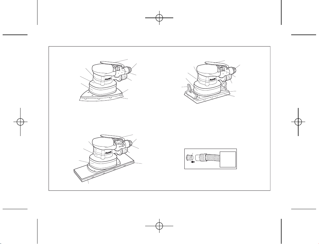
PARTI DELLA MACCHINA
1 - Etichetta di identificazione
2 - Leva di comando immissione aria compressa
3 - Comando regolatore di velocità
4 - Corpo macchina
5 - Attacco aria compressa
6 - Attacco tubo di aspirazione Ø int. 29 mm.
7 - Cuffia di aspirazione
8 - Piastra base
9 - Piastra gomma forata e velcrata
10 - Leva fermacarta (RE21ACM)
MESSA IN FUNZIONE
Prima di mettere in funzione la macchina accertarsi che:
- l’imballo sia integro e non mostri segni di danneggiamento
dovuti a trasporto e magazzinaggio;
- la macchina sia completa; controllare che numero e natura dei
componenti siano conformi a quanto riportato sul presente
libretto;
- l’impianto di produzione e distribuzione di aria compressa a
disposizione sia in grado di soddisfare i requisiti indicati in
tabella e riportati sulla targhetta di identificazione.
MONTAGGIO DELLA MACCHINA
Montare il raccordo aria compressa (non fornito) avvitandolo
nella apposita sede (5).
RACCORDO DI ADDUZIONE ARIA COMPRESSA
La macchina viene fornita sprovvista del raccordo di
alimentazione; a scelta dell’utilizzatore possono essere usati sia
raccordi ad innesto rapido sia portagomma adeguati purchè
entrambi abbiano un foro di passaggio aria da mm. 8. Nel
secondo caso occorre fissare stabilmente con una fascetta stringi-
tubo il tubo di alimentazione al portagomma.
MONTAGGIO DELLA CARTA ABRASIVA
RE21ACM
- Sollevare la leva fermacarta (10) premendo sull’apposita
appendice;
9.2180 RE21A_ott2015:libretto RA90A-RA125A-RA150A OK.qxd 15/05/2017 11.50 Pagina 5

6
- inserire la carta abrasiva sotto la leva fino alla battuta quindi
rilasciare il fermacarta e che i fori della carta siano in
corrispondenza di quelli della piastra di gomma;
- ripetere le operazioni precedenti sul lato opposto della piastra,
tenendo ben tesa la carta e controllare che i bordi siano paralleli
al bordo della piastra, prima di rilasciare la leva.
RS21A - RE21ALN
- Premere il foglio di carta abrasiva velcrata sulla piastra avendo
cura che i fori della carta siano in corrispondenza di quelli della
piastra di gomma;
- fare attenzione che la piastra gomma forata velcrata non presenti
tracce di polvere o altro.
PRIMA DELLA MESSA IN SERVIZIO
Accertarsi che:
- il regolatore di velocità (3) sia nella posizione MAX;
- raccordo e tubo di adduzione aria compressa siano in perfetto
stato;
- il dispositivo di azionamento sia efficiente operando però a
macchina non alimentata;
- tutti i componenti della macchina siano montati correttamente e
non presentino segni di danneggiamento;
- la macchina sia correttamente collegata ad un sistema
d’aspirazione idoneo ed efficiente.
AVVIAMENTO E FERMATA
- Avviamento: spingere la leva di comando (2) verso il corpo
macchina e mantenerla premuta.
- Fermata: rilasciare la leva di comando.
FUNZIONAMENTO DI PROVA
Avviare la macchina e controllare che non siano presenti
vibrazioni anomale.
In caso contrario spegnere la macchina immediatamente e
provvedere ad eliminare le anomalie.
REGOLAZIONE DEL NUMERO DI GIRI
La regolazione del numero dei giri si ottiene manovrando
opportunamente il regolatore (3) da MAX a OFF. La scelta della
velocità va fatta in funzione delle caratteristiche dei fogli di carta
abrasiva e del materiale da lavorare.
SOSTITUZIONE DELLA CARTA ABRASIVA
RE21ACM
- Sollevare le leve fermacarta (10) premendo sulle apposite
appendici e rimuovere il foglio usato ;
- applicare il nuovo foglio seguendo le istruzioni date al capitolo
“MONTAGGIO DELLA CARTA ABRASIVA”.
RS21A - RE21ALN
- Asportare a strappo il foglio di carta usato applicare il nuovo
foglio di carta abrasiva premendo lo stesso sulla piastra ed
avendo cura che i fori praticati sullo stesso coincidano con i fori
di aspirazione praticati sulla piastra.
UTENSILI DI LAVORO AMMESSI
- RE21ALN - RE21ACM: fogli di carta abrasiva forata velcrata per
levigatrici orbitali;
- RS21A: carta abrasiva velcrata delta.
MANUTENZIONE
Tutte le operazioni vanno eseguite a macchina scollegata.
A fine lavoro, od in caso di necessità, spolverare con getto di aria
compressa il corpo macchina.
Lubrificare periodicamente (ogni 50 ore di lavoro) la macchina
inserendo 2/3 gocce d'olio per uso specifico nell'attacco aria
compressa dell'utensile tenendo lo stesso in posizione
verticale con l'attacco in alto. Dopo questa operazione
collegare la macchina all'alimentazione e azionarla per alcuni
secondi.
Prima di riporre l'utensile per un lungo periodo di inattività
procedere all'operazione di lubrificazione come sopra descritto.
Si escludono dalla garanzia tutti i danni derivanti da una
scorretta o inadeguata lubrificazione.
Non sono ammessi altri interventi da parte dell'utente.
9.2180 RE21A_ott2015:libretto RA90A-RA125A-RA150A OK.qxd 15/05/2017 11.50 Pagina 6

7
EMISSIONE DI RUMORE/ VIBRAZIONE
Il livello equivalente di pressione sonora (rumorosità) e Il valore
quadratico medio dell'accelerazione sono misurati secondo le
norme: UNI EN ISO 15744 - EN ISO 28927.
Livello di Pressione acustica / Potenza sonora Livello di vibrazioni su 3 assi
LPA LWA Incertezza ahIncertezza
dB(A) m/s
2
RE21ACM 78 89 3 3.80 1.20
RE21ALN 79 90 3 3.95 1.35
RS21A 79 90 3 3.75 1.00
ATTENZIONEI valori di misura indicati sono validi solo per
utensili nuovi.Nell’impiego quotidiano i valori di rumore e
vibrazione cambiano.
I valori di emissione indicati sono comparativi e utilizzabili per una
valutazione provvisoria dei rischi di esposizione dell’operatore
durante il periodo di lavoro.La corretta valutazione del periodo di
lavoro deve comprendere anche i tempi di funzionamento a
vuoto e di arresto dell’utensile. I valori di emissioni indicati sono
rappresentativi delle principali applicazioni dell’utensile. Se
l’utensile viene utilizzato per altre applicazioni, con altri accessori
o se non viene sottoposto a regolare manutenzione, i valori di
emissione possono aumentare sensibilmente durante il
funzionamento.
Utilizzare le cuffie di protezione!
SMALTIMENTO
Il prodotto, quando giunge a fine vita, non deve essere disperso
nell’ambiente o gettato tra i rifiuti domestici, ma deve essere
smaltito presso i centri di raccolta differenziata autorizzati
(contattare le autorità locali competenti per conoscere dove
smaltire il prodotto secondo le norme di legge). Il corretto
smaltimento del prodotto contribuisce alla tutela della salute e
alla salvaguardia dell’ambiente.Lo smaltimento abusivo del
prodotto comporta sanzioni a carico dei trasgressori.
DICHIARAZIONE DI CONFORMITÀ
Dichiariamo sotto la nostra responsabilità che l'utensile portatile,
al quale fa riferimento il presente manuale, è conforme ai
Requisiti Essenziali della Direttiva:
2006/42/CE Macchine
Le prove/verifiche sono eseguite in accordo alle seguenti Normative:
UNI EN ISO 11148-8 - UNI EN ISO 15744 - UNI EN ISO 28927
Fascicolo tecnico presso:
RUPES S.p.A.
Via Marconi, 3A
20080 VERMEZZO (Mi) - Italy
Vermezzo (MI), 03/02/2014
IL PRESIDENTE
G. Valentini
S.p.A
9.2180 RE21A_ott2015:libretto RA90A-RA125A-RA150A OK.qxd 15/05/2017 11.50 Pagina 7

TECHNICAL DATA
TYPE
WORKING PRESSURE bar/PSI
AIR CONSUMPTION l/min
SPEED CONTROL
RPM
Ø ORBITAL DIAMETER mm
PLATE SHAPE
PLATE DIMENSIONS mm
VELCROED DRILLED RUBBER PLATE
EXTRACTION SYSTEM
WEIGHT Kg
ENGLISH TRANSLATION OF ORIGINAL OPERATING INSTRUCTION 8
Warning symbol/ Warning messageI SO7010 - W001
Read instruction manual ISO7010 - M002
Wear eye protection ISO7010 - M004
Wear ear protection ISO7010 - M003
Wear a mask ISO7010 - M016
Wear a gloves ISO7010 - M009
CE compliant
EurAsian Mark
Arrow Act in the direction indicated by the arrow direction
SIMBOLS
Some of the following symbols may be used on your tool. Please study them and learn their meaning. Proper interpretation of these
symbol will allow you to operatethe tool better and safer.
RE21ACM
6.2/90
380
YES
0 ÷ 11.000
3
RECTANGULAR
80x130
YES
CENTRALIZED
0,870
RS21A
6.2/90
380
YES
0 ÷ 11.000
3
DELTA
-
YES
CENTRALIZED
0,850
RE21ALN
6.2/90
380
YES
0 ÷ 11.000
3
RECTANGULAR
70x198
YES
CENTRALIZED
0,900
(*) The tool must be connected to a suitable dust extraction system (not supplied).
9.2180 RE21A_ott2015:libretto RA90A-RA125A-RA150A OK.qxd 15/05/2017 11.50 Pagina 8

9
GENERAL WARNINGS
The tool must be connected to a suitable dust extraction system
(not supplied).
SAFETY AND ACCIDENT PREVENTION INSTRUCTIONS
The safety and accident prevention instructions are reported in the
“SAFETY INSTRUCTION” booklet which forms an integral part of
these documents; the operating instructions indicate the
additional information required specifically for use of the tool.
Never use the tools without the safety guards.
Any operations carried out on the tool must be effected with the
tool disconnected.
Before starting the tool, ensure that it is held tightly and not in
contact with the work surface.
The electric tool must be connect to a suitable dust extraction unit
and applicable safety regulations must be observed if dusts
dangerous to health are likely to occur during sanding.
Due to risks that may arise during sanding, we recommend the
constant use of P.S.D. (personal safety devices such as gloves,
headphones, goggles, face masks, etc.) according to laws in
force to prevent or reduce accident probability.
Warning! Carry out the lubrication process outlined in the
maintenance paragraph. The appliance continues to work for a
few seconds after it has been switched off.
CORRECT USAGE
The sanders are designed for sanding wood, plastic, composite
materials, paint/varnish, filling material and similar materials.
Metal and materials with an asbestos content must not be
processed with these tools.
The tools must not be damp nor operated in a damp environment
for electrical safety reasons.
The tools may only be used for dry sanding.
Make sure the work piece is sufficiently fastened.
In the event of improper use, the user is fully liable for any
damages or accidents.
PARTS OF THE TOOL
1 - Identification plate
2 - Compressed air on/off lever
3 - Speed control
4 - Tool body
5 - Compressed air connection
6 - 29 mm. int. Ø suction pipe connection
7 - Suction cowling
8 - Base plate
9 - Velcroed drilled rubber plate
10 - Paper clamping lever (RE21ACM)
STARTING UP
Before starting-up the tool, ensure that:
- the packaging is complete and does not show signs of having
been damaged during storage or transport;
- the tool is complete; check that the number and type of components
comply with that reported in this instruction booklet;
- the available compressed air production and distribution plant is
capable of satisfying the requirements reported on the tool’s
identification plate.
ASSEMBLING THE TOOL
Assemble the compressed air connection (not supplied) by
screwing it into its seating (5).
COMPRESSED AIR CONNECTION
The tool is supplied without the compressed air connection; the
user can use either a quick release coupling or hose type
connection according to his needs, purke they have an hole of air
passing mm. 8. In the latter case the air line must be fixed to the
nozzle by a hose clip.
INSERTING THE ABRASIVE PAPER
RE21ACM
- Lift the paper clamping lever (10) by pressing the lever release;
- insert the abrasive paper under the lever until it rests against the
9.2180 RE21A_ott2015:libretto RA90A-RA125A-RA150A OK.qxd 15/05/2017 11.50 Pagina 9

10
stop, then release the lever and that the holes in the paper
coincide with the suction holes in the rubber plate;
- repeat this operation on the opposite side of the plate, keeping
the paper taut and checking that the edges are parallel with the
edges of the plate before releasing the lever.
RS21A - RE21ALN
- Press the velcro backed abrasive paper in position, ensuring that
the holes in the paper coincide with the suction holes in the
rubber plate;
- make sure that there is no dust or other matter on the drilled
rubber plate..
BEFORE STARTING THE TOOL
Ensure that:
- the speed control (3) is in MAX position;
- the compressed air feed line and connection are in perfect
working order;
- the start lever is working properly. This must be done with the air
supply switched off;
- all the components of the tool are mounted correctly and do not
show any signs of damage;
- the tool must be connected to a suitable and efficient aspiration
device.
STARTING AND STOPPING
- Starting: push the control lever (2) forward towards the body of
the tool and keep it pressed.
- Stopping: release the control lever.
TEST RUN
Start the tool and check that there are no unusual vibration, no
dismatching of the abrasive paper disc.
Otherwise switch-off the tool immediately and eliminate the
cause.
SELECTING THE RPM
The number of revolutions can be adjusted by using the speed control
(3) from MAX to OFF. The choice of speed depends on the charac-
teristics of the abrasive paper disc and the material to be worked.
REPLACING ABRASIVE PAPER
RE21ACM
- Lift the paper clamping lever (10) by pressing the release device
and remove the used paper;
- applying on rubber plate the new abrasive paper following the
instructions in the chapter on “INSERTING THE ABRASIVE
PAPER”.
RS21A - RE21ALN
- Remove tear the paper used to apply the new sheet of abrasive
paper by pressing the same on the plate and taking care that the
holes drilled on the same coincide with the holes suction
practiced on the plate.
USABLE ABRASIVE PAPER
- RE21ALN - RE21ACM: Velcro sand paper with holes for extraction;
- RS21A: Delta Velcro sand paper with holes for extraction.
MAINTENANCE
All maintenance operations are carried out with the tool
disconnected from the compressed air supply.
At the end of each work session, or when required, remove any
dust from the body of the tool using a jet of compressed air.
Lubricate the machine regularly by inserting 2/3 drops of specific
oil into the compressed air connection, keeping the device in a
vertical position, with the connection facing upwards. After this
operation, connect the machine to the power supply and set it in
motion for a few seconds.Lubricate the machine as described
above before storing it for long periods of inactivity.All damages
deriving from incorrect or inadequate lubrication are excluded from
the warranty.
No other maintenance operations must be undertaken by the user.
Maintenance and cleaning of the inner parts, must be carried out
only by an authorized customer-service workshop.
9.2180 RE21A_ott2015:libretto RA90A-RA125A-RA150A OK.qxd 15/05/2017 11.50 Pagina 10

11
INFORMATOIN NOISE / MEAN ACCELERATION VALUE
The tools are suppressed in accordance for the prevention and
elimination of radiodisturbances measured in accordance with
standard:
UNI EN ISO 15744 - EN ISO 28927.
Sound pressure level / Sound power level 3 axis vibration level
LPA LWA Uncertainty ahUncertainty
dB(A) m/s
2
RE21ACM 78 89 3 3.80 1.20
RE21ALN 79 90 3 3.95 1.35
RS21A 79 90 3 3.75 1.00
DANGER The indicate measurements refer to new power
tools.Daily usa causes the noise and vibration values to
change.
Displayed emission values are comparative and are to be
employed fora provisional assessment of the operator’s risk
exposure during the work period.Appropriate evaluation of work
period must also include tool’s idle and stopperiods. These
emission values represent the tool’s main applications. If the tool
is used for other applications, with other accessories, or if it does
notundergo regular maintenance, emission values can
significantly increaseduring operations.
Use hearing protection!
DISPOSAL
The product, when it reaches the end of its life, must not be
dispersed in theenvironment or thrown away as household waste.
It must be disposed atauthorized recycling centres (contact your
local authorities to know where todispose of the product
according to the law). The correct disposal of the
productcontributes to the health and preservation of the
environment.Illegal disposal of the product will entail penalties
against the offenders.Disposing of the product correctly
contributes to protecting human health andsafeguarding the
environment. Any illegitimate disposal of the product will
bepunishable by law.
CONFORMITY DECLARATION
We declare on our responsibility that the hand-held power tool, which is
mentioned in the present operating manual, is in conformity with the
Essential Requirements of Safety of the following Directive:
2006/42/CE Macchine
he tests have been carried out in accordance with following Standards:
UNI EN ISO 11148-8 - UNI EN ISO 15744 - UNI EN ISO 28927
Technical file at:
RUPES S.p.A.
Via Marconi, 3A
20080 VERMEZZO (Mi) - Italy
Vermezzo (MI), 03/02/2014
IL PRESIDENTE
G. Valentini
S.p.A
9.2180 RE21A_ott2015:libretto RA90A-RA125A-RA150A OK.qxd 15/05/2017 11.50 Pagina 11

TYPE
PRESSION DE SERVICE bars/PSI
CONSOMMATION AIR l/min
REGLAGE DE LA VITESSE
TOURS/min
Ø DIAMETRE ORBITE mm
FORME PLAQUE
DIMENSION PLAQUE mm
PLAQUE CAOUTCHOU PERFORÉE A VELCRO
SYSTEME D’ASPIRATION
MASSE Kg
FRANÇAIS CONVERSION DES INSTRUCTIONS DE FONCTIONNEMENT ORIGINAL 12
Symbole d'avertissement / Message d'avertissement ISO7010 - W001
Lisez le manuel d'instruction ISO7010 - M002
Porter des lunettes de protection ISO7010 - M004
Porter une protection de l'oreille ISO7010 - M003
Porter un masque ISO7010 - M016
Porter un des gants ISO7010 - M009
Conforme aux normes CE
L'outil est inclus dans la liste EurAsian
Flèche Agissant dans la direction indiquée par la direction de la flèche
SYMBOLES
Certains des symboles suivants peuvent être utilisés sur votre outil. Se il vous plaît de les étudier et apprendre leur signification. Une
interprétation correcte de ces symboles vous permettra d'utiliser l'outil meilleur et plus sûr.
RE21ACM
6.2/90
380
OUI
0 ÷ 11.000
3
RETTANGULAIRE
80x130
OUI
CENTRALE
0,870
RS21A
6.2/90
380
OUI
0 ÷ 11.000
3
DELTA
-
OUI
CENTRALE
0,850
RE21ALN
6.2/90
380
OUI
0 ÷ 11.000
3
RETTANGULAIRE
70x198
OUI
CENTRALE
0,900
(*) La machine doit fonctionner reliée à un système d’aspiration approprié (non fourni).
CARACTERISTIQUES TECHNIQUES
9.2180 RE21A_ott2015:libretto RA90A-RA125A-RA150A OK.qxd 15/05/2017 11.50 Pagina 12

13
RECOMMANDATIONS GENERALES
La machine doit fonctionner reliée à un système d’aspiration
approprié (non fourni).
INSTRUCTIONS RELATIVES A LA SECURITE ET
A LA PROTECTION CONTRE LES ACCIDENTS DU TRAVAIL
Les instructions relatives à la sécurité et à la protection contre les
accidents du travail sont contenues dans le fascicule
"INDICATIONS RELATIVES A LA SECURITE" qui fait partie
intégrante de la présente documentation; le livret d'instructions
relatives à l'utilisation indique uniquement les informations
complémentaires qui sont étroitement linées à l'utilisation
spécifique de la machine.
Ne jamais faire fonctionner les outils sans avoir monté les
dispositifs de protection.
Chaque opèration effectuée sur la machine ait lieu la machine
étant dèbranchée.
Avant sa mise en marche, la machine soit empoignée solidement
et qu’elle ne soit pas en contact avec la surface de travail.
En cas de poussières nocives pour la santé, il faut connecter
l’outil électrique à un dispositif d’aspiration adéquat et respecter
les prescriptions de sécurité applicables au matériau.
A cause des risques qui peuvent survenir durant le ponçage, il est
conseillé de toujours utiliser tous les D.P.I. (dispositifs de protection
individuels tels que gants, oreillettes, lunettes de protection,
masques de protection des voies respiratoires, etc.) selon les
normes en vigueur pour prévenir ou réduire les risques d'accidents.
Attention! Suivre les normes de lubrification reportées du
paragraphe entretien.
L'outil continue à fonctionnner pendant quelques secondes après
l'arrêt!
UTILISATION CONFORME
Les ponceuses sont destinées au ponçage du bois, des matières
synthétiques, des matériaux composites, de la peinture / du
vernis, du mastic et des matériaux similaires.
Les métaux et du matériau comportant de l’amiante ne doivent
pas être usinés.
Pour des raisons de sécurité électrique, les machines ne doivent
pas être humides ni fonctionner dans un environnement humide.
Contrôler que le poids de la pièce à travailler est suffisamment
fixé. En cas d'utilisation non conforme aux buts prévus,
l'utilisateur sera tenu responsable des éventuels dommages et
accidents.
PARTIES DE LA MACHINE
1 - Ètiquette d’identification
2 - Levier de commande entrée air comprimé
3 - Régulateur de vitesse
4 - Corps de la machine
5 - Raccord air comprimé
6 - Bouche d’aspiration Ø 29 mm
7 - Coiffe d’aspiration
8 - Plaque de base
9 - Plaque caoutchou perforée a velcro
10 - Levier de blocage du papier abrasif (RE21ACM)
MISE EN SERVICE
Avant de mettre la machine en service, s'assurer que:
- l'emballage est intégre et qu'il ne montre aucun signe d'endomma-
gements dus au transport et au stockage;
- la machine est complète; s'assurer que le nombre et la nature
des composants sont conformes aux indications contenues
dans le présent livret d'instructions;
- l’installation de production et de distribution d’air comprimé à
disposition est en mesure de satisfaire les conditions indiquées
dans le tableau et sur la plaquette d’identification.
MONTAGE DE LA MACHINE
Monter le raccord air comprimé (non fourni) en le vissant dans le
siége prévu à cet effet (5).
RACCORD D’ARRIVEE AIR COMPRIME
La machine est fournie sans raccord d’alimentation; au choix de
l’utilisateur, il est possible d’utiliser des raccords à attache rapide
ou des porte-joints appropiés à conditions qu’ils aient une
ouverture de passage d’air mm. 8.
Dans le second cas, fixer solidement le tuyau d’alimentation au
porte-joint à l’aide d’un collier serre-tube.
9.2180 RE21A_ott2015:libretto RA90A-RA125A-RA150A OK.qxd 15/05/2017 11.50 Pagina 13

14
MONTAGE DU PAPIER ABRASIF
RE21ACM
- Soulever le levier de blocage du papier (10) en appuyant sur la
languette prévu à cet effet;
- mettre le papier abrasif sous le levier jusqu’à la butée puis
relâcher le levier et que les trous du papier correspondent aux
trous qui se trouvent sur la plaque en caoutchouc;
- répéter les opérations précédentes sur l’autre côté de la plaque,
en faisant en sorte que le papier soit bien tendu et en contrôlant
que ses bords soient parallèles au bord de la plaque avant de
relâcher le levier.
RS21A- RE21ALN
- Appliquer sur la plaque la feuille de papier à velcro par pression
en veillant à ce que les trous du papier correspondent aux trous
qui se trouvent sur la plaque en caoutchouc;
- faire attention a ce que la plaque velcro n’ait aucune trace de
poussière ou autre.
AVANT LA MISE EN SERVICE
S’assurer que:
- le régulateur de vitesse (3) est en position MAX;
- raccord et tuyau d’arrivée air comprimé sont en parfait état;
- l’interrupteur de mise en marche/arrêt est efficace en agissant
cependant lorsque la fiche est débranchée;
- tous les composants de la machine sont montés correctement et
ne présentent pas de signes d’endommagement;
- la machine soit relièe à un dispositif d’aspiration appropriè et efficace.
MISE EN MARCHE ET ARRET
- Mise en marche: pousser le levier de commande (2) vers le
corps de la machine et ne pas relâcher.
- Arrêt: relâcher le levier de commande.
FONCTIONNEMENT D'ESSAI
Mettre la machine en marche et s’assurer qu’il n’y a pas de
vibrations anomales et que le disque abrasif n’est pas décentré.
Dans le cas contraire, énteindie la machine immédiatement et
éliminer les anomalies.
SELECTION DU NOMBRE DE TOURS
Le réglage du nombre de tours s'effectue en agissant de manière
adéquate sur le régulateur (3) de MAX à OFF. Le choix de la
vitesse doit être fait en fonction des caractéristiques des disques
du papier abrasif et du matèriau à usiner.
REMPLACEMENT DU PAPIER ABRASIF
RE21ACM
- Soulever les leviers de blocage (10) du papier en appuyant sur
les languettes prévues à cet effect et retirer le papier usé;
- Appliquer sur la plaque de caoutchouc le nouveau papier abrasif
en suivant les instructions dans le chapitre sur “MONTAGE DU
PAPIER ABRASIF”.
RS21A- RE21ALN
- Supprimer déchirer le papier utilisé pour appliquer la nouvelle
feuille de papier abrasif en appuyant sur la même sur la plaque
et en prenant soin que les trous forés sur la même coïncident
avec les trous aspiration pratiquée sur la plaque.
OUTILS DE TRAVAIL ADMIS
- RE21ALN - RE21ACM: Papier abrasif velcro avec trous pour
l'aspiration.
- RS21A: Papier abrasif velcro delta mm avec trous pour l'aspiration.
ENTRETIEN
Toutes le opèrations.sur la machine ait lieu la machine étant
dèbranchée de l’installation d’air comprimé.
A la fin du travail et en cas de nècessitè, dèpoussièrer le corps de
la machine à l’aide d’un jet d’air comprimè.
Lubrifier régulièrement la machine, en mettant 2/3 gouttes
d'huiles pour usage spécifique au niveau du raccordement de
l'air comprimé de l'outil en le tenant en position verticale avec
le raccordement tourné vers le haut. Après cette opération,
brancher la machine et l'allumer pendant quelques
secondes.Avant de ranger l'outil pour une longue période
d'inactivité, procéder à l'opération de lubrification, comme
décrit ci-dessus.Tous les dommages dérivant d'une mauvaise
lubrification sont exclus de la garantie.
9.2180 RE21A_ott2015:libretto RA90A-RA125A-RA150A OK.qxd 15/05/2017 11.50 Pagina 14

15
Aucune autre intervention de l’utilisateur n’est pas admise.
Tous les travaux d’entretien et les travaux de polissage des piéces
internes, doivent être effectuer par un Centres d’Assistance autorisé.
FORMATION DU BRUIT / VALEUR MOYENNE DE L'ACCELERATION
Le niveau équivalent de la pression sonore (niveau de bruit) e
lavaleur quadratique moyenne de l'accèlérationest est mesurés
conformément aux normes
UNI EN ISO 15744 - EN ISO 28927.
Niveau de pression acoustique / Niveau de puissance acoustique Niveau des vibration selon 3 axies
LPA LWA Incertitude ahIncertitude
dB(A) m/s
2
RE21ACM 78 89 3 3.80 1.20
RE21ALN 79 90 3 3.95 1.35
RS21A 79 90 3 3.75 1.00
Attention! Les valeurs de mesure indiquées s’appliquent
aux appareils neufs. Pendant le mise en ceuvre
quotidienne, les valeurs de bruit et devibrations varient.
Utilisez une protection acoustique!
Les valeurs d’émission relevées sont comparatives et ne doivent
être employées que pour une évaluation provisoire du risque
auquel l’opérateur est exposé au cours de la période de travail.
Une évaluation appropriée de la période de travail doit également
inclure des périodes d’inactivité et d’arrêt de l’outil. Ces valeurs
d’émission sont représentatives des principales applications
auxquelles l’outil est destiné. Si l’outil est utilisé dans d’autres
applications, avec d’autres accessoires, ou s’il ne bénéficie pas
d’un entretien régulier, les valeurs d’émission en cours de
fonctionnement peuvent s’accroître dans des proportions
significatives.
ÉLIMINATION
Le produit, lorsqu’il atteint sa fin de vie, ne doit pas être dispersé
dans l’environnement ou jeté avec les déchets ménagers, mais
doit être collecté dans un centre de tri sélectif afin d’être éliminé
(Veuillez contacter les autorités locales pour obtenir les centres
de tri conformes à la législation).L’élimination correcte du produit
contribue à la protection de la santé et de l’environnement. Des
sanctions contre les personnes ne respectant pas l’élimination
correcte du produit seront prises. L’élimination correcte du
produit contribue à la protection de la santé et de
l’environnement. En n’éliminant pas le produit conformément à la
loi en vigueur vous vous exposez à des sanctions.
DÉCLARATION DE CONFORMITÉ
Nous déclarons sous notre responsabilité que l'outil portable, auquel
se réfère le présent manuel, est conforme aux Conditions
Essentielles de la Directive:
2006/42/CE Machines
Les essais/contrôles sont effectués conformément aux normes
suivantes:
UNI EN ISO 11148-8:2012 - UNI EN ISO 15744 - UNI EN ISO 28927.
Dossier technique auprès de:
RUPES S.p.A.
Via Marconi, 3A
20080 VERMEZZO (Mi) - Italy
Vermezzo (MI), 03/02/2014
IL PRESIDENTE
G. Valentini
S.p.A
9.2180 RE21A_ott2015:libretto RA90A-RA125A-RA150A OK.qxd 15/05/2017 11.50 Pagina 15

TECHNISCHE DATEN
TYP
BETRIEBSDRUCK bar/PSI
LUFTVERBRAUCH l/min
DREHZAHLREGELUNG
UMDREHUNGEN U/min
SCHWINGKREIS Ø mm
FORM DER BODENPLATTE
ABMESSUNGEN BODENPLATTE mm
GUMMI GELOCHT KLETTSYSTEM BODENPLATTE
ABSAUGVORRICHTUNG
GEWICHT Kg
DEUTSCH ÜBERSETZUNG DES URSPRÜNGLICHEN BEDIENUNGSANLEITUNG 16
Wichtige Sicherheitshinweise / Geräts folgendeAnweisungen ISO7010 - W001
Lesen Sie vor Bedienung ISO7010 - M002
Schutzbrille ISO7010 - M004
Gehörschutz tragen ISO7010 - M003
Tragen Sie eine Maske ISO7010 - M016
Schutzhandschuhe ISO7010 - M009
Prüfzeichen
EurAsian Qualitätskennzeichen
Pfeil Act in der durch den Pfeil angegebenen Richtung Richtung
PIKTOGRAMM
Einige der folgenden Symbole können am Werkzeug vorhanden sein. Bitte studieren und lernen, ihre Bedeutung. Die richtige
Interpretation wird die optimale Nutzung und sichere Werkzeug ermöglichen.
RE21ACM
6.2/90
380
JA
0 ÷ 11.000
3
RECHTEK
80x130
JA
CENTRAL
0,870
RS21A
6.2/90
380
JA
0 ÷ 11.000
3
DREIECK
-
JA
CENTRAL
0,850
RE21ALN
6.2/90
380
JA
0 ÷ 11.000
3
RECHTEK
70x198
JA
CENTRAL
0,900
(*) Die genannten Gerätes dürfen nur zusammen mit einer passenden Staubabsaugung betrieben werden (kein Lieferbestandteil).
9.2180 RE21A_ott2015:libretto RA90A-RA125A-RA150A OK.qxd 15/05/2017 11.50 Pagina 16

17
ALLGEMEINE HINWEISE
Die genannten Gerätes dürfen nur zusammen mit einer passenden
Staubabsaugung betrieben werden (kein Lieferbestandteil).
SICHERHEITS- UND UNFALLVERHÜTUNGSVORSCHRIFTEN
Die Sicherheits- und Unfallverhütungsvorschriften sind im
beiliegenden Helft "HINWEISE ZUR SICHERHEIT" enthalten,
welches vollwertiger Bestandteil der vorliegenden Dokumentation
ist. Diese Gebrauchsanleitung nennt daher nur die
Zusatzinformationen, die den spezifischen Einsatz dieses Gerätes
betreffen.
Alle Arbeiten an der Maschine nur bei gezogenem
Druckluftanschluß ausfuhren Werkzeuge niemals ohne
aufmontierte Schutzvorrichtungen betreiben.
Die Maschine vor dem Einschalten fest in der Hand halten. Sie darf
die zu bearbeitende Fläche nicht berühren.
Entstehen beim Schleifen gesundheitsgefährdende Stäube,
schließen Sie das Elektrowerkzeug an eine geeignete
Absaugeinrichtung an und beachten Sie die für den Arbeitsstoff
geltenden Sicherheits-vorschriften.
Aufgrund der mit dem Schleifen verbundenen Risiken wird
empfohlen, entsprechend den geltenden Richtlinien zur
Unfallverhinderung bzw. -reduzierung stets die gesamte P.S.A.
(persönliche Schutz-Ausrüstung, wie zum Beispiel Handschuhe,
Ohrschützer, Schutzbrillen, Atemschutzmaske, usw.) zu tragen.
Achtung! Bitte beachten Sie die Hinweise zur Schmierung auf
Abschnitt Wartung. Das Werkzeug läuft nach dem Ausschalten
noch für einige Sekunden weite!
BESTIMMNGSGEMÄßE VERWENDUNG
Bestimmungsgemäß sind die Schleifer zum Schleifen von Holz,
Kunststoff, Verbundwerkstoff, Farbe / Lack, Spachtelmasse und
ähnlichen Werkstoffen vorgesehen.
Metall und asbesthaltiges Material dürfen nicht bearbeitet werden.
Wergen der elektrischen Sicherheit, dürfen die Maschinen nicht
feucht sein und nicht in feuchter Umgebund betrieben werden.
Die Maschinen dürfen nur für Trockenschliff verwendet werden.
Überprüfen, ob das Werkstück ausreichend befestigt ist.
Wird das Gerät für nicht vorgesehene Zwecke benutzt, übernimmt
der Benutzer jede Verantwortung für eventuelle Schäden oder
Unfälle.
BAUTEILE DER MASCHINE
1 - Schild mit Geräte-Kenndaten
2 - Bedienhebel z. Einleitung der Druckluft
3 - Drehzahleinstellung
4 - Gerätegehäuse
5 - Druckluftanschluß
6 - Anschluß f. Absaugschlauch; Innenweite Ø 29 mm
7 - Absaughaube
8 - Grundplatte
9 - Gummi gelocht Klettsystem Bodenplatte
10 - Schleifblatt-Befestigungsklammer (RE21ACM)
INBETRIEBNAHME
Vor einer Inbetriebnahme des Geräts sollten Sie sicherstellen:
- daß die Verpackung unversehrt ist und keine Beschädigungen
durch Transport bzw. Lagerung aufweist;
- daß das Gerät vollständig ist, also Anzahl und Art der Geräte-
komponenten mit den Angaben in dieser Bedienungsanleitung
überein stimmen;
- ob die Druckluftaufbereitung und -zuleitung die in der Tabelle
sowie auf dem Geräteschild genannten Anforderungen erfüllt.
Die Kenndaten des Geräteschilds.
ZUSAMMENBAU DER MASCHINE
Das Druckluft-Kupplungsstück (nicht mitgeliefert) in die
entsprechende Bohrung (5) einschrauben.
DRUCKLUFTANSCHLUß
Die Maschine wird ohne Druckluft-Kupplungsstück geliefert. Der
Anwender kann hierzu wahlweise eine Schnellkupplungs-
Stecktülle bzw. einen Stecknippel anschließen vorausgeselzt daß
es ein 8 mm.
Loch für den Luftdurchfluss gibt. Im zweiten Fall muß man den
Sclauch mit einer Schelle stabil auf dem Stecknippel festspannen.
9.2180 RE21A_ott2015:libretto RA90A-RA125A-RA150A OK.qxd 15/05/2017 11.50 Pagina 17

18
ANBRINGEN DES SCHLEIFPAPIERS
RE21ACM
- Die Schleifblatt-Befestigungsklammer (10) durch Druck auf das
dazu vorgesehene Endstück anheben;
- das Schleifpapier bis es anliegt unter die Klammer schieben, dann
den Hebel loslassen daß seine Löcher über den Absauglöchern in
der Gummi-Bodenplatte liegen;
- diesen Vorgang am anderen Ende der Bodenplatte wiederholen.
Dazu das Schleifpapier gut straffen und prüfen, ob die Ränder mit den
Kanten der Bodenplatte abschließen. Dann die Klammer loslassen.
RS21A - RE21ALN
- Das Haftschleifpapier auflegen und andrücken. Dabei darauf
acten, daß seine Löcher über den Absauglöchern in der Gummi-
Bodenplatte liegen.
- Darauf achten; dass die Klettverschlussplatte nicht verstaubt oder
anderweitig beschmutzt ist.
VOR DER INBETRIEBNAHME
Stellen Sie folgende Sicher:
- der Drehzahlregler (3) in Stellung MAX ist;
- Schlauch und Kupplungsstück der Druckluftversorgung sind in
einwandfreiem Zustand;
- der EIN/AUS-Schalter funktioniert einwandfrei. Allerdings ohne
Druckluft;
- Sämtliche Gerätekomponenten sind ordnungsgemäß montiert
und weisen keine Zeichen von Beschädigung auf;
- die Maschine muß an eine sinngemäß bemessene und
funktionstüchtige Staubabsaugung angeschlossen sein.
EINSCHALTEN UND AUSSCHALTEN
- Einschalten: den Bedienhebel (2) zum Gerätegehäuse hin
bewegen und gedrückt halten.
- Ausschalten: den Bedienhebel loslassen.
TESTLAUF
Schalten Sie das Gerät ein und stellen Sie sicher, daß es nicht
ungewöhnlich vibriert, order die Schleifteller f. Haftschleifcheiben
berührt wird.
Andernfalls das Gerät sofort ausschalten und die Störung beheben.
EINSTELLUNG DER DREHZAHL
Die Drehzahlregelung wird über entsprechendes Betätigen des
Reglers erzielt (3) von MAX bis OFF. Wählen Sie die Drehzahl
passend zur Art der Schleifpapierscheibe sowie den Eigenschaften
des bearbeiteten Materials.
AAUSWECHSELN DES SCHLEIFPAPIERS
RE21ACM
- Die Schleifpapierklammern durch Drücken (10) an den Enden
öffnen und das verbrauchte Blatt abnehmen;
- Anwendung auf GUMMI GELOCHT KLETTSYSTEM BODENPLATTE
Schleifpapier gemäß den Anweisungen in der Kapitel “ANBRINGEN
DES SCHLEIFPAPIERS”
RS21A - RE21ALN
- Entfernen reißen die verwendet die neue anzuwenden Papier Blatt
Schleifpapier durch Drücken des gleichen auf der Platte und
Aufpassen, dass die Bohrungen auf der gleichen gebohrt mit den
Löchern zusammenfällt Saug praktiziert auf dem Teller.
ZULÄSSIGE WERKZEUGE
- RE21ALN - RE21ACM: Schleifpapier mit Klett mit Absaugöffnungen;
- RS21A: Schleifpapier mit Klettdelta und mit Absaugöffnungen.
WARTUNG DES GERÄTES
Sämtliche Eingriffe bei gezogenem an der Maschine nur bei
gezogenem Druckluftanschluß ausfuhren.
Das Gerät nach der Arbeit sowie bei Bedarf mit Druckluft von Staub
befreien.
Schmieren Sie die Maschine regelmäßig. Geben Sie hierzu 2-3
Tropfen Spezialöl in den Stutzen der Pressluftzufuhr am
Werkzeug. Halten Sie das Werkzeug hierbei senkrecht, mit dem
Stutzen nach oben. Schließen Sie die Maschine anschließend an
die Stromversorgung an und lassen Sie sie für einige Sekunden
laufen.Führen Sie die vorstehend beschriebene Schmierung auch
durch, wenn das Werkzeug für längere Zeit eingelagert werden
soll.Schäden, die durch falsche oder unangemessene
Schmierung verursacht werden, sind von der Garantie
ausgeschlossen.
9.2180 RE21A_ott2015:libretto RA90A-RA125A-RA150A OK.qxd 15/05/2017 11.50 Pagina 18

19
Sonstige Eingriffe durch den Geräteanwender sind nicht zulässig.
Für die Wartung und die periodische Reinigung von den inneren oder
andere Bedürfnisse wenden Sie sich bitte an einer autorisierten
Kundendienststelle an.
INFORMATIONEN SCHALLPEGEL/MITTLEREBESCHLEUNIGUNG
Der Schalldruckpegel (Geräuschentwicklung) und die mittlere
quadratischeBeschleunigungder Maschine, gemessen gemäß
UNI EN ISO 15744 - EN ISO 28927.
Schalldruckpegel / Schalleistungspegel 3-Achsen Vibrationspegel
LPA LWA
Messunsicherheit
ah
Messunsicherheit
dB(A) m/s
2
RE21ACM 78 89 3 3.80 1.20
RE21ALN 79 90 3 3.95 1.35
RS21A 79 90 3 3.75 1.00
Achtung! Di angegebenen Messwerte gelten für neue
Geräte. ImtäglichenEinsatz verändern sich Geräusch-und
chwingungswerte.
Gehörschutz benutzen!
Bei den gezeigten Pegelwerten handelt es sich um
Vergleichswerte, die zu einer vorläufigen Einschätzung des
Risikos für den Bedienenden während der Arbeitszeit dienen. Für
eine angemessene Einschätzung der Arbeitszeit müssen die
Zeiten berücksichtigt werden, in denen sich das Gerät im
Ruhezustand befindet oder ausgeschaltet ist. Diese Werte wurden
anhand der Haupteinsatzgebiete des Geräts ermittelt. Wenn das
Gerät für andere Aufgaben oder mit anderen Zubehörprodukten
verwendet wird oder keine regelmäßigen Wartungsarbeiten
durchgeführt werden, können diese Werte beim Betrieb deutlich
überschritten werden.Achtung!
ENTSORGUNG
Wenn das Produkt das Ende seiner Lebensdauer erreicht hat, darf
es nicht in der Umwelt freigesetzt oder zusammen mit dem
Hausmüll weggeworfen werden, sondern muss bei autorisierten
Recycling-Sammelzentren entsorgt werden (kontaktieren Sie die
kompetenten örtlichen Behörden, um zu erfahren, wo das
Produkt laut Gesetz zu entsorgen ist). Die korrekte Entsorgung
des Produkts trägt zum Schutz der Gesundheit und der Erhaltung
der Umwelt bei.Eine illegale Entsorgung des Produkts hat
Strafmaßnahmen zu Lasten des Gesetzesübertreters zur
Folge.Die korrekte Entsorgung des Produkts trägt zum Schutz
der Gesundheit und der Umwelt bei. Die missbräuchliche
Entsorgung des Produkts zieht Sanktionen zu Lasten des
Verursachers nach sich.
KONFORMITÄTSERKLÄRUNG
Wir erklären in alleiniger Verantwortung, dass das Handwerkszeug ,
das ist in der vorliegenden Betriebsanleitung erwähnt, ist im Einklang
mit der Grundlegenden Anforderungen der Sicherheit der Direktive:
2006/42/CE Maschinenrichtlinie
Die Test sind in Übereinstimmung mit den nachfolgenden
Standards durchgeführt worden:
UNI EN ISO 11148-8:2012 - UNI EN ISO 15744 - UNI EN ISO 28927.
Technische Unterlagen bei:
RUPES S.p.A.
Via Marconi, 3A
20080 VERMEZZO (Mi) - Italy
Vermezzo (MI), 03/02/2014
IL PRESIDENTE
G. Valentini
S.p.A
9.2180 RE21A_ott2015:libretto RA90A-RA125A-RA150A OK.qxd 15/05/2017 11.50 Pagina 19

DATOS TECNICOS
TYPO
PRESION DE OPERACION bar/PSI
CONSUMO AIRE l/min
REGULACION DE LA VELOCIDAD
REVOLUCIONES/min (r.p.m.)
Ø DIAMETRO ORBITA mm
FORMA DE LA PLACA
DIMENSIONES PLACA mm
PLACA GOMA PERFORADA CON VELCRO
SISTEMA DE ASPIRACION
MASA Kg
ESPAÑOL TRADUCCIÓN DE MANUAL DE INSTRUCCIONES ORIGINAL 20
Advertencias Advertencia / Peligro ISO7010 - W001
Lea las instrucciones ISO7010 - M002
Use gafas protectoras ISO7010 - M004
Use protección para los oídos ISO7010 - M003
Use una máscara ISO7010 - M016
Use guantes de protección ISO7010 - M009
Marca de conformidad
La herramienta se incluye en la lista de EurAsian
Flecha Ley en la dirección indicada por la flecha de dirección
SÍMBOLOS
Algunos de los siguientes símbolos pueden estar presentes en su herramienta. Le suplicamos estudiarlos y aprender su significado. La
interpretación correcta permitirá el mejor uso y una herramienta segura.
RE21ACM
6.2/90
380
SI
0 ÷ 11.000
3
RECTANGULAR
80x130
SI
CENTRALE
0,870
RS21A
6.2/90
380
SI
0 ÷ 11.000
3
DELTA
-
SI
CENTRALE
0,850
RE21ALN
6.2/90
380
SI
0 ÷ 11.000
3
RECTANGULAR
70x198
SI
CENTRALE
0,900
(*) La máquina debe funcionar conectada con un adecuado sistema de aspiración (no suministrado).
9.2180 RE21A_ott2015:libretto RA90A-RA125A-RA150A OK.qxd 15/05/2017 11.50 Pagina 20
This manual suits for next models
2
Table of contents
Languages:
Other Rupes Sander manuals