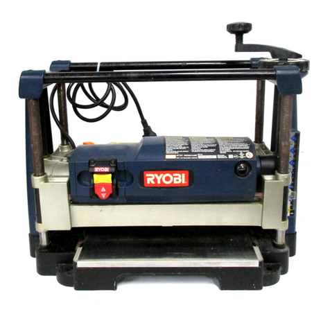
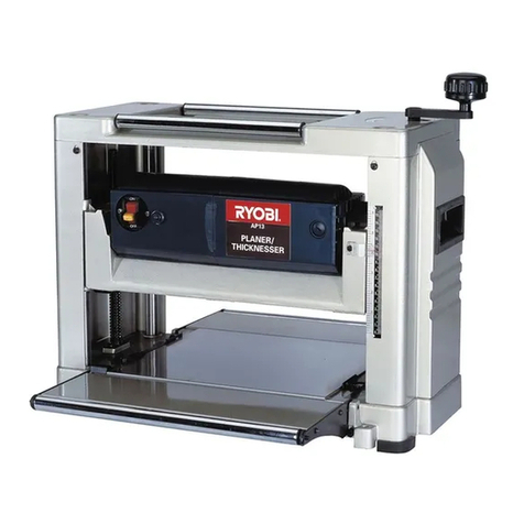
Ryobi AP1300 User manual

OPERATOR'S MANUAL
13 in. (330 mm) Portable Planer
Model AP1300
THANK YOU FOR BUYING A RYOBI PORTABLE PLANER.
YournewplanerhasbeenengineeredandmanufacturedtoRyobi'shighstandardsfordependability,easeofoperation,
andoperatorsafety.Properlycaredfor,itwillgiveyouyearsofrugged,trouble-freeperformance.
CAUTION: Carefully read through this entire operator's manual before using your new planer.
PaycloseattentiontotheRulesforSafeOperation,Warnings,andCautions.Ifyouuseyourtoolproperlyandonlyfor
whatitisintended,youwillenjoyyearsofsafe,reliableservice.
PleasefilloutandreturntheWarrantyRegistrationCardsowecanbeoffutureservicetoyou.
ThankyouagainforbuyingRyobitools.
SAVE THIS MANUAL FOR FUTURE REFERENCE

Page2
TABLE OF CONTENTS
■TableofContents,Introduction,andProductSpecifications ...........................................................................................2
■RulesForSafeOperation.............................................................................................................................................3-5
■Electrical............................................................................................................................................................................6
■UnpackingandLooseParts..............................................................................................................................................7
■Features............................................................................................................................................................................8
■Assembly...........................................................................................................................................................................9
■Adjustments..............................................................................................................................................................10-12
■Operation..................................................................................................................................................................13-14
■Maintenance .............................................................................................................................................................15-16
■Troubleshooting............................................................................................................................................................. 17
■PartsOrdering/Service.................................................................................................................................................. 18
PRODUCT SPECIFICATIONS
SPECIFICATIONS:
FeedRate 25FPM
Rating 15Amperes
NoLoadSpeed 9,900RPM
Input 120volts,60Hz,ACOnly
Max.PlaningHeight 6in.(152mm)
Max.PlaningWidth 13in.(330mm)
MaxPlaningDepth 1/8in.(3mm)
NetWeight 77lbs.(35kg.)
INTRODUCTION
Yourportableplanerhasmanyfeaturesformakingcutting
operations more pleasant and enjoyable. Safety,
performance,anddependabilityhavebeengiventoppriority
inthe designofthis planermakingit easytomaintain and
operate.
CAUTION:
Carefully read through this entire operator's manual
before using your new tool. Pay close attention to the
Rules for Safe Operation, and all SafetyAlert Symbols
includingDanger,WarningandCaution.Ifyouuseyour
tool properly and only for what it is intended, you will
enjoyyearsofsafe,reliableservice.
Look for this symbol to point out important safety precautions.
It means attention!!! Your safety is involved.

Page3
Safeoperationofthispowertoolrequiresthatyoureadand
understandthisoperator'smanual and all labelsaffixedto
thetool.Safetyisacombinationofcommonsense,staying
alert,andknowinghowyourtoolworks.
READ ALL INSTRUCTIONS
■KNOW YOUR POWER TOOL. Read the operator's
manualcarefully. Learnthemachine's applicationsand
limitations as well as the specific potential hazards re-
latedtothistool.
■GUARD AGAINST ELECTRICAL SHOCK by prevent-
ingbodycontactwithgroundedsurfacessuchaspipes,
radiators,ranges,refrigeratorenclosures.
■KEEP GUARDS IN PLACE andingoodworkingorder.
■REMOVE WRENCHES AND ADJUSTING KEYS. Getin
the habit - before turning on tool - that hex keys and
adjustingwrenchesareremovedfromtool.
■KEEP THE WORK AREA CLEAN. Clutteredworkareas
andworkbenchesinviteaccidents.DO NOT leavetools
orpiecesofwoodonthemachinewhileitisinoperation.
■DO NOT USE IN DANGEROUS ENVIRONMENTS. Do
not use power tools near gasoline or other flammable
liquids,indamporwetlocations,orexposethemtorain.
Keeptheworkareawelllit.
■KEEP CHILDREN AND VISITORS AWAY. All visitors
shouldwearsafetyglassesandbekeptasafedistance
fromworkarea.Donotletvisitorscontacttoolorexten-
sioncordwhileoperating.
■MAKE WORKSHOP CHILDPROOF withpadlocksand
masterswitchesorbyremovingstarterkeys.
■DO NOT FORCE THE TOOL. Itwilldothejobbetterand
saferattherateforwhichitwasdesigned.
■USE THE RIGHT TOOL FOR THE JOB. Donotforcethe
toolorattachmenttodoajobitwasnotdesignedfor.Use
itonlythewayitwasintended.
■USE THE PROPER EXTENSION CORD. Make sure
yourextensioncordisingoodcondition.Useonlyacord
heavyenoughtocarrythecurrentyourproductwilldraw.
An undersized cord will cause a drop in line voltage
resultinginlossofpowerandoverheating.Awiregage
size (A.W.G.) of at least 14 is recommended for an
extensioncord25feetorlessinlength.Ifindoubt,usethe
next heavier gage. The smaller the gage number, the
heavierthecord.
■INSPECT TOOL CORDS AND EXTENSION CORDS
PERIODICALLY and,ifdamaged,haverepairedatyour
nearestauthorizedservicecenter.Stayconstantlyaware
of cord location and keep it well away from the moving
blade.
■DRESS PROPERLY. Donotwearlooseclothing,gloves,
neckties, rings, bracelets, or other jewelry that can get
caughtanddrawyouintomovingparts.Nonslipfootwear
is recommended. Also wear protective hair covering to
containlonghair.
■ALWAYS WEAR SAFETY GLASSES WITH SIDE
SHIELDS. Everydayeyeglasseshaveonlyimpact-resis-
tantlenses;theyareNOT safetyglasses.
RULES FOR SAFE OPERATION
■WEAR A DUST MASK to keep from inhaling fine par-
ticles.
■PROTECT YOUR HEARING. Wear hearing protection
duringextendedperiodsofoperation.
■SECURE WORK. Use clamps or a vise to hold work
whenpractical.It'ssaferthanusingyourhandandfrees
bothhandstooperatetool.
■DO NOT OVERREACH. Keep proper footing and bal-
anceatalltimes.
■MAINTAIN TOOLS WITH CARE. Keeptoolssharpand
clean for better and safer performance. Follow instruc-
tionsforlubricatingandchangingaccessories.
■DISCONNECT ALL TOOLS. When not in use, before
servicing,orwhenchangingattachments,alltoolsshould
bedisconnected.
■AVOID ACCIDENTAL STARTING. Besureswitchisoff
whenplugginginanytool.
■USE RECOMMENDED ACCESSORIES. Consult the
operator's manual for recommended accessories. The
useofimproperaccessoriesmaycauseriskofinjury.
■NEVER STAND ON TOOL. Seriousinjurycouldoccurif
thetoolistippedorifthebladeisunintentionallycontacted.
■CHECK DAMAGED PARTS. Before using the tool, a
guardorotherpartthatisdamagedshouldbecarefully
checked to determine that it will operate properly and
perform its intended function. Check for alignment of
movingparts,bindingofmovingparts,breakageofparts,
mounting and any other conditions that may affect its
operation.Aguardorotherpartthatisdamagedmustbe
properly repaired or replaced by an authorized service
centertoavoidriskofpersonalinjury.
■DIRECTION OF FEED. Feedworkintoabladeorcutter
againstthedirectionorrotationofthebladeorcutteronly.
■NEVER LEAVE TOOL RUNNING UNATTENDED, TURN
THE POWER OFF. Donotleavetooluntilitcomestoa
completestop.
■FIRMLY CLAMP OR BOLT yourtooltoaworkbenchor
tableatapproximatelyhipheight.
■KEEP HANDS AWAY FROM CUTTING AREA. Donot
reachunderneathworkorinbladecuttingpathwithyour
handsandfingersforanyreason.Alwaysturnthepower
off.
■DO NOT ABUSE CORD. Neveryankcordtodisconnect
it from receptacle. Keep cord from heat, oil, and sharp
edges.
■USE ONLY OUTDOOR EXTENSION CORDS. Useonly
extension cords with the marking "Acceptable for use
withoutdoorappliances;storecordsindoorswhilenotin
use". Use extension cords with an electrical rating not
lessthantheplaner'selectricalrating.Alwaysdisconnect
theextensioncordfromtheoutletbeforedisconnecting
theproductfromtheextensioncord.
■DO NOT USE TOOL IF SWITCH DOES NOT TURN IT
ON AND OFF. Havedefectiveswitchesreplacedbyan
authorizedservicecenter.

Page4
■DO NOT attempttoturncutter-headwithhands.
■WHEN SERVICING, use only identical Ryobi replace-
mentparts.Useofanyotherpartsmaycreateahazard
orcauseproductdamage.
■NEVER USE THIS TOOL IN AN EXPLOSIVE ATMO-
SPHERE. Normal sparking of the motor could ignite
fumes.
■IF ANY PART OF THIS TOOL IS MISSING or should
break,bend,orfail in any way, or shouldanyelectrical
component fail to perform properly, shut off the power
switch,removetheplugfromthepowersourceandhave
damaged,missing,orfailedpartsreplacedbeforeresum-
ingoperation.
■DO NOT OPERATE THIS TOOL WHILE UNDER THE
INFLUENCE OF DRUGS, ALCOHOL, OR ANY MEDI-
CATION.
■ALWAYS STAY ALERT! Donotallowfamiliarity(gained
from frequent use of your planer) to cause a careless
mistake.ALWAYS REMEMBER thatacarelessfraction
ofasecondissufficienttoinflictseriousinjury.
■STAY ALERT AND EXERCISE CONTROL. Watchwhat
youaredoingandusecommonsense.Do not operate
tool when you are tired. Do not rush.
■MAKE SURE THE WORK AREA HAS AMPLE LIGHT-
ING toseetheworkandthatnoobstructionswillinterfere
withsafeoperationBEFORE performinganyworkusing
yourplaner.
■ALWAYS TURN OFF THE TOOL beforedisconnecting
ittoavoidaccidentalstartingwhenreconnectingtopower
supply. NEVER leave the tool unattended while con-
nectedtoapowersource.
■SAVE THESE INSTRUCTIONS. Refertothemfrequently
andusethemtoinstructotherusers.Ifyouloansomeone
thistool,loanthemtheseinstructionsalso.
WARNING:
Somedustcreatedbypowersanding,sawing,grinding,
drilling,andotherconstructionactivitiescontainschemi-
calsknowntocausecancer,birthdefectsorotherrepro-
ductiveharm.Someexamplesofthesechemicalsare:
• leadfromlead-basedpaints,
• crystallinesilicafrombricksandcementand
othermasonryproducts,and
• arsenicandchromiumfromchemically-treated
lumber.
Yourriskfromtheseexposuresvaries,dependingonhow
oftenyoudothistypeofwork.Toreduceyourexposure
to these chemicals, work in a well ventilated area and
workwithapprovedsafetyequipment,suchasthosedust
masksthatarespeciallydesignedtofilteroutmicroscopic
particles.
RULES FOR SAFE OPERATION
■KEEP TOOL DRY, CLEAN, AND FREE FROM OIL AND
GREASE. Alwaysuseacleanclothwhencleaning.Never
usebrakefluids,gasoline,petroleum-basedproducts,or
anysolventstocleantool.
■NEVER PERFORM THE PLANING OPERATION with
thecutterheadordriveguardremoved.
■NEVER MAKE A PLANING CUT deeper that 1/8 in.
(3mm)
■DO NOT PLANE MATERIAL shorterthan14in.(356mm)
ornarrowerthan3/4in.(19mm).
■MAINTAIN THE PROPER RELATIONSHIP betweenthe
infeed and outfeed surfaces and the cutter head knife
path.
■SUPPORT THE WORKPIECE ADEQUATELY atall
timesduringoperation;maintaincontroloftheworkat
alltimes.
■DO NOT BACK THE WORK towardtheinfeedtable.
■DO NOT ATTEMPT TO PERFORM anabnormalorlittle
used operation without the use of sturdy and adequate
jigs,fixtures,stops,andthelike.
■NEVER cut more than one piece at a time. DO NOT
STACK morethanoneworkpieceontheplanertableat
atime.
■BEFORE STARTING UP, recheck to make certain all
holdingscrewsaretight.
■STOP THE MACHINE and recheck the cutter head gib
screwsandknivesfortightnessafterabout50hoursof
operation.
■DO NOT FORCE FEED THE WORKPIECE throughthe
machine.Lettheplanerapplytheproperfeedrate
■CHECK THE FEED ROLLERS occasionally to be sure
therearenochipsorsawdustbetweenanycomponents.
Iftherollersare not seated firmly, theywillnotholdthe
stock firmly against the bed and are likely to cause
kickback.
■PLANE ONLY SOUND LUMBER; there should be no
looseknotsandasfewtightknotsaspossible.Makesure
theworkpieceisfreefromnails,screws,stones,orother
foreignobjectsthatcouldbreakorchiptheknives.
■NEVER STAND DIRECTLY IN LINE with either the
infeedoroutfeedsides.Standofftooneside.
■MAKE SURE THE KNIVES ARE ATTACHED as de-
scribedintheoperationsection.Theknivesaresharpand
can easily cut your hand. Use caution in handling the
knivesandcutterheadguard.
■NEVER PUT YOUR FINGERS into the dust chute or
undertheknifeguard.
■ALLOW THE CUTTER HEAD toreachfullspeedbefore
usingtheplaner.
■REPLACEMENT PARTS. Allrepairs,whetherelectrical
or mechanical, should be made at your nearest autho-
rizedservicecenter.

SAVE THESE INSTRUCTIONS

Page5
RULES FOR SAFE OPERATION
Thepurposeofsafetysymbolsistoattractyourattentiontopossibledangers.Thesafetysymbols,andtheexplanations
withthem,deserveyourcarefulattentionandunderstanding.Thesafetywarningsdonotbythemselveseliminateany
danger.Theinstructionsorwarningstheygivearenotsubstitutesforproperaccidentpreventionmeasures.
SYMBOL MEANING
SAFETY ALERT SYMBOL:
Indicatesdanger,warningorcaution.Maybeusedinconjunctionwithothersymbolsorpictographs.
DANGER: Failuretoobeyasafetywarningwillresultinseriousinjurytoyourselfortoothers.Always
followthesafetyprecautionstoreducetheriskoffire,electricshockandpersonalinjury.
WARNING: Failuretoobeyasafetywarningcanresultinseriousinjurytoyourselfortoothers.Always
followthesafetyprecautionstoreducetheriskoffire,electricshockandpersonalinjury.
CAUTION: Failuretoobeyasafetywarningmayresultinpropertydamageorpersonalinjurytoyourself
ortoothers.Alwaysfollowthesafetyprecautionstoreducetheriskoffire,electricshockandpersonal
injury.
Note: Advisesyouofinformationorinstructionsvitaltotheoperationormaintenanceoftheequipment.
WARNING:
Theoperationofanypowertoolcanresultinforeignobjectsbeingthrownintoyoureyes,whichcan
resultinsevereeyedamage.Beforebeginningtooloperation,alwayswearsafetygogglesorsafety
glasseswithside shields and afullfaceshieldwhen needed. We recommendWideVisionSafety
Mask for use over eyeglasses or standard safety glasses with side shields. Always wear eye
protectionwhichismarkedtocomplywithANSIZ87.1.
WARNING:
Do not attempt to operate this tool until you have read
thoroughly and understand completely all instructions,
safety rules, etc., contained in this manual. Failure to
comply can result in accidents involving fire, electric
shock,orseriouspersonalinjury.Saveoperator'smanual
andreviewfrequentlyforcontinuingsafeoperation,and
instructingotherswhomayusethistool.
IMPORTANT
Servicing requiresextremecareandknowledgeandshould
be performed only by a qualified service technician. For
service we suggest you return the tool to your nearest
RYOBI AUTHORIZED SERVICE CENTER forrepair.When
servicing,useonlyidenticalRyobireplacementparts.
SAFETY AND INTERNATIONAL SYMBOLS
Thisoperator’smanualdescribessafetyandinternationalsymbolsandpictographsthatmayappearonthisproduct.
Readtheoperator’smanualforcompletesafety,assembly,operatingandmaintenance,andrepairinformation.
MEANING
Donotexposetorainoruseindamplocations

Page6
ELECTRICAL
EXTENSION CORDS
Useonly3-wireextensioncordsthathave3-prongground-
ingplugsand3-polereceptaclesthatacceptthetool'splug.
Whenusingapowertoolataconsiderabledistancefromthe
powersource,useanextensioncordheavyenoughtocarry
thecurrentthatthetoolwilldraw.Anundersizedextension
cordwillcausea drop in linevoltage,resultinginaloss of
power and causing the motor to overheat. Use the chart
providedbelowtodeterminetheminimumwiresizerequired
in an extension cord. Only round jacketed cords listed by
Underwriter'sLaboratories(UL)shouldbeused.
Length of Extension Cord Wire Size (A.W.G.)
Upto25feet 14
26-50feet 12
Whenworkingwiththetooloutdoors,useanextensioncord
that is designed for outside use. This is indicated by the
lettersWA onthecord'sjacket.
Before using an extension cord, inspect it for loose or
exposedwiresandcutorworninsulation.Repairorreplace
adamagedorworncordimmediately.
CAUTION:
Keepthecordawayfromthecuttingareaandposition
thecordsothatitwillnotbecaughtonmaterial,tools,or
otherobjectsduringcutting.
GROUNDING
PIN
COVER OF GROUNDED
OUTLET BOX
ELECTRICAL CONNECTION
YourRyobiPortablePlanerispoweredbyaprecisionbuilt
electric motor. It should be connected to a power supply
that is 120 volts, 60 Hz. If the machine does not operate
whenpluggedintoanoutlet,doublecheckthepowersupply.
GROUNDING INSTRUCTIONS
In the event of a malfunction or breakdown, grounding
provides a path of least resistance for electric current to
reducetheriskofelectricshock.Thistoolisequippedwithan
electriccordhavinganequipment-groundingconductorand
agroundingplug.Theplugmustbepluggedintoamatching
outletthatisproperlyinstalledandgroundedinaccordance
withalllocalcodesandordinances.
Donotmodifytheplugprovided.Ifitwillnotfittheoutlet,have
theproperoutletinstalledbyaqualifiedelectrician.Improper
connectionoftheequipment-groundingconductorcanresult
in a risk of electric shock. The conductor with insulation
havinganoutersurfacethatisgreenwithorwithoutyellow
stripes is the equipment-grounding conductor. If repair or
replacementoftheelectriccordorplugisnecessary,donot
connect the equipment-grounding conductor to a live
terminal.
Checkwithaqualifiedelectricianorservicepersonnelifthe
groundinginstructionsarenotcompletelyunderstood,orifin
doubtastowhetherthetoolisproperlygrounded.
Repairorreplaceadamagedorworncordimmediately.
Thistoolisintendedforuseonacircuitthathasanoutletlike
theoneshownin
Figure 1.
Italsohasagroundingpinlikethe
oneshown.
CORD STORAGE BAG
See Figure 1.
For convenience and safety, your planer comes equipped
withacordstoragebag.Thisstoragebagisontheunder-
neathsideofthereartableextensionandallowsyoutofold
thecordandplaceitinthebagforstorageortransport.

Page7
UNPACKING
■Carefully lift the tool from the carton and place it on a
level work surface. This machine is heavy. Avoid back
injuryandgethelpwhenneeded.
■Do not discard the packing materials until you have
carefullyinspectedthetool,identifiedalllooseparts,and
satisfactorilyoperatedyournewplaner.
■Examineallpartstomakesurenobreakageordamage
hasoccurredduringshipping.
Ifanypartsaredamagedormissing,donotattempttoplug
inthepowercordandturntheswitchonuntilthedamaged
ormissingpartsareobtainedandareinstalledcorrectly.
WARNING:
Topreventaccidentalstartingthatcouldcausepossible
seriouspersonalinjury,assembleallparts,makesureall
adjustmentsarecomplete, and makesureallfasteners
are secure before connecting portable planer to power
supply. Portable planer should never be connected to
power supply when you are assembling parts, making
adjustments,installingorremovingblades,orwhennotin
use.
Your portable planer has been shipped completely
assembledexceptforthedustchuteanddustchuteknobs.
■Removeallloosepartsfromthecarton.
■Separate and check with the list of loose parts.
See
Figure 2.
■Removethepackingmaterialsfromaroundyourplaner.
WARNING:
Ifanypartsaremissing,donotoperatethistooluntilthe
missingpartsarereplaced.Failuretodosocouldresult
inpossibleseriouspersonalinjury.

Page8

Page9
ASSEMBLY
INSTALLING THE DUST CHUTE
See Figure 4.
■Unplugyourplaner.
WARNING:
Failuretoturntheplaneroff,removetheswitchkey,and
unplugtheplanerbeforeservicingormakingadjustments
could result in accidental starting causing possible
seriouspersonalinjury.
■Fromthebackofthemachine,locatethetwoscrewson
thecutterheadassembly.
See Figure 4.
Turningcoun-
terclockwise,looseneachscrew.
■Slide the dust chute between the lock washer and the
cutter head assembly, resting the dust chute on the
rubberbumper.
■Insertthetwodustchuteknobs,turningclockwise.
■Securelytightenthescrewsanddustchuteknobs.
Note: To minimize sawdust accumulation on your
workpiece, attach either a 2-1/2 in. (64 mm) or 4 in.
(102mm)shopvachosetotheendofthedustchute.
MOUNTING PLANER TO WORKBENCH
If your planer is to be used in a permanent location, it is
recommendedyousecureittoaworkbenchorotherstable
surface.Whenmountingtheplaner to a workbench, holes
should be drilled through the supporting surface of the
workbench.
■Markholesonworkbenchwhereplaneristobemounted
using holes in planer base as a template for hole
pattern.
■Drillfourholesthroughworkbench.
■Placeplaneronworkbench aligning holes intheplaner
basewithholesdrilledintheworkbench.
■Insertfourbolts(notincluded)andtightensecurelywith
lockwashersandhexnuts(notincluded).
Note: All bolts should be inserted from the top. Install
thelockwashersandhexnutsfromtheundersideofthe
workbench.
Supporting surface where planer is mounted should be
examinedcarefullyafter mounting to insure that no move-
ment during use can result. If any tipping or walking is
noted,secureworkbenchorsupportsurfacebeforebegin-
ningplaningoperation.
CLAMPING PLANER TO WORKBENCH
See Figure 5.
If the planer is to be used as a portable tool, it is recom-
mendedyoufastenitpermanentlytoamountingboardthat
can easily be clamped to a workbench or other stable
surface.Themountingboardshouldbeofsufficientsizeto
avoid tipping while planer is in use. Any good grade ply-
wood or chipboard with a 3/4 in. (19 mm) thickness is
recommended. Fig.5
Fig.4
■Mark holes on board where planer is to be mounted
using holes in planer base as a template for hole
pattern.
■Follow last three steps in section
Mounting Planer to
Workbench.
Iflagboltsareused,makesuretheyarelongenoughtogo
through holes in planer base and material the planer is
being mounted to. If machine bolts are used, make sure
bolts are long enough to go through holes in planer base,
the material being mounted to, and the lock washers and
hexnuts.
SCREWS
DUST
CHUTE
DUST CHUTE
KNOBS

Page10
ADJUSTMENTS
LEVELING THE TABLE EXTENSIONS
See Figure 6.
Theinfeedandoutfeedtableextensions are attached to
the planer. Shipped in a folded, "upright" position, the
table extensions must be in the "down" position before
planing can begin. For accurate planing, table exten-
sionsmustbelevelwiththeplanertable.
Note: Foroptimumperformance,alwayschecktomake
sure the table extensions are level before beginning
planingoperations.
To Level:
■Unplugyourplaner.
WARNING:
Failuretounplugyourplanercouldresultinaccidental
startingcausingpossibleseriouspersonalinjury.
■Place a straight edge or level across both the planer
tableandtableextensions.
■If adjustment is necessary, lift table extensions and
loosenlocknuts.Adjuststopscrews(oneoneachside)
untilextensiontableislevelwithplanertable.
■Press down on the table extension to ensure the table
extensionisproperlyseated.
■Tighten lock nuts securely when adjustments are com-
plete.
Note: Fourscrewsattachtableextensionstosupport
bars; loosening these screws may aid in leveling
tableextensions.
BLADE HEIGHT ADJUSTMENT
See Figure 7.
Raisingandloweringthedepthadjustmenthandlecontrols
thedepthofcutonyourplaner.
Note: Never adjust blade height with cutter lock in the
"locked"position(pushedtothefarright).
To Raise:
■Push cutter lock to the left to unlock cutter head
assembly.
■Turn the depth adjustment handle clockwise to desired
height.
■Oncecutterheadisindesiredposition,lockcutterhead
assembly in place by pushing cutter lock handle to the
right.
To Lower:
■Push cutter lock to the left to unlock cutter head
assembly.
■Turn the depth adjustment handle counterclockwise to
desiredheight.
■Once cutter head assembly is in the desired position,
lock cutter head in place by pushing cutter lock handle
totheright.
Note: Each complete rotation of the handle moves the
cutterheadassembly5/64in.(2mm).
Fig.6
Fig.7
LOCK NUT
STOP SCREWS
TABLE
EXTENSION
PLANER
TABLE
LOCK
CUTTER HEAD
ASSEMBLY
DEPTH
ADJUSTMENT
HANDLE
UNLOCK
1-3/4
1-1/2
1-1/4
1/4
0

Page11

Page 12
ADJUSTMENTS
CUTTER BLADE SIDEWAYS ADJUSTMENT
See Figures 10 and 11.
During the use of your planer, tiny nicks may appear on
the cutter blades. This is a result of picking up sand or
other particles on the workpiece and then running the
workpiece through the planer. To eliminate any imper-
fections during the planing process, adjust one or both
cutter blades laterally.
To Adjust:
■Unplug your planer.
WARNING:
Failure to turn the planer off, remove the switch key, and
unplug the planer could result in accidental starting
causing possible serious personal injury.
■Lower the cutter head assembly.
■From the back of the planer, remove the two screws
holding the dust chute in place.
■Remove the dust chute then lift off the safety cover.
■Rotate the cutter block until it locks in place (every 180°
turn).
Note: From beneath the cutter head assembly, using the
planer table as a mirror, touch the threaded spindle where
it meets the planer table. Carefully move your fingers up
toward the drive belt until you touch it. Turn the drive belt
with your fingers until the cutter head locks in place
(see
Figure 11.)
WARNING:
To avoid injury, NEVER rotate the cutter block by hand.
■Loosen the socket head bolts holding the blade binder
and cutter blade to the cutter block.
■Move the cutter blade to the left or right side up to 3/64 in.
(1 mm) laterally using a flat head screwdriver.
■Retighten the socket head bolts securely.
■Place the safety cover on the cutter head assembly
leaving the screws loose.
■Reinstall the dust chute by slipping it under the screws
and lock washers (see page 9).
■Tighten screws securely.
Note: Cutter blades require only slight adjustments to
offset planing imperfections.
Fig. 10
Fig. 11
SAFETY
COVER
CUTTER
BLOCK
SCREWS
CUTTER
BLOCK
BLADE
BINDER

Page13
ON
OPERATION
GETTING STARTED
Before turning on the planer, check for loose fasteners,
fittings, or hardware. Be sure the dust cover is securely
mountedandthatthebladecutterrotatesfreely.
Lower the cutter head assembly to approximately 1 in.
(25mm)abovetheplanertablesurface.Withoutputtingany
loadontheplaner,testthemotorbyturningtheplaneronand
allowingit to reach full speed.If the planer sounds exces-
sivelyloudorhasexcessivevibration,turnoffthemachine
immediately and check again for any loose hardware, re-
tighteninganyyoumayfind.
THICKNESS PLANING
Thickness planing sizes workpiece to desired thickness
whilecreatingasmooth,levelsurface.Thicknessofeach
cut will depend on type of wood (hardwood versus soft-
wood), width of workpiece, straightness, dryness, and
graincomposition.Wheneverworkingwithanewtypeof
wood,make thin test cuts on a scrap piece of wood first
todeterminepotentialproblemswiththeworkpiece.
PLANING
Thickness planers work best if at least one side of the
workpiece has a flat surface. When both sides of a
workpieceisrough,useasurfaceplanerorjointerfirstto
define the initial flat surface. Plane one side of the
workpiece then flip the workpiece and plane the surface
ofthereverseside.
Always plane both sides of a workpiece to reach the
desired thickness. This will leave the workpiece with
uniform moisture to prevent warp during the drying pro-
cess.
Whenoneendoftheworkpieceisthickerthantheoppo-
siteendbymorethan1/8in.(3mm),makeseveralcuts
with the planer starting with light planing cuts first. Re-
member,lightcutscreateafinerfinishthanheaviercuts.
■Do not plane a workpiece less than 3/16 in. (5 mm)
thick.
■Donotplaneaworkpiecelessthan3/4in.(19mm)wide.
■Donotplaneworkpieceshorterthan14in.(356mm)long
asthiswillcausekickback.
■Donotplanemorethanoneworkpieceatatime.
■Donotlowerthecutterheadassemblylowerthan3/16in.
(5mm)
Donotcontinuouslyusetheplanersetatthemaximumdepth
ofcut(1/8in.,3mm)andatfullwidthofcut(13in.,330mm).
Continuous use at maximum cutting capacity will damage
themotor.
WARNING:
Neverplaneworkpiecewithlooseknotsorforeignobjects.
Do not plane workpieces that are severely bowed,
twisted, or knotted. Cutter blades can dull, chip, or
breakcausingpossibleseriouspersonalinjury.
Fig.12
SWITCH KEY
OFF
.WARNING:
Alwayswear safetygogglesorsafetyglasseswithside
shieldsduringpowertooloperationorwhenblowingdust.
Ifoperationisdusty,alsowearadustmask.
Worncutterbladeswillaffectcuttingaccuracy.Planingwith
dull or nicked cutter blades may produce ridges or rough
workpiecesurfaces.
Gumandpitchonthecutterbladeswillcausethemtowear
prematurely.Usingagumandpitchremovertokeepyour
cutterbladescleanwillprolongtheirwear.
Refertothe
Maintenance Section
ofthisoperator'smanual
for instructions on how to remove and replace or turn the
cutterblades.
Note: Cutter blades are double-edged and can be turned
once to the opposite, unused edge before replacement is
required.CutterbladesmustALWAYS bereplacedasaset.
LOCKING THE SWITCH
See Figure 12.
■Waituntiltheplanerhascometoafullandcompletestop.
■PlacetheswitchintheOFF position,removetheswitch
keyfromtheswitchassembly.Storekeyinsafeplace.

Page14

Page15
WARNING:
When servicing, use only identical Ryobi replacement
parts.Useofanyotherpartmaycreateahazardorcause
productdamage.
GENERAL
Avoid using solvents when cleaning plastic parts. Most
plastics are susceptible to damage from various types of
commercialsolventsandmaybedamagedbytheiruse.Use
cleanclothstoremovedirt,carbondust,etc.
WARNING:
Donotatanytimeletbrakefluids,gasoline,petroleum-
based products, penetrating oils, etc. come in contact
with plastic parts. They contain chemicals that can
damage,weakenordestroyplastic.
CUTTER BLADE REPLACEMENT
See Figure 15.
Your planer is equipped with two double-edged cutter
blades attached to a rotating cutter block. Worn cutter
bladeswillaffectcuttingaccuracyandmayproduceridges
ontheworkpiece.
To Replace:
■Unplugyourplaner.
WARNING:
Failuretoturntheplaneroff,removetheswitchkey,and
unplug the planer before servicing or making adjust-
mentscouldresultinaccidentalstartingcausingpossible
seriouspersonalinjury.
MAINTENANCE
■Lowerthecutterheadassembly.
■From the back of the planer, remove the two socket
headscrewsholdingthedustchuteinplace.
■Removethedustchutethenliftoffthesafetycover.
■Ifnecessary,rotatethecutterblockuntilitlocksinplace
(every180°turnthecutterblockwilllock).
Note: Rotating the cutter block is accomplished from
beneaththecutterheadassembly.Usingtheplanertable
asamirror,touchthethreadedspindlewhereitattaches
totheplanertable.Carefullymove yourfingersupuntil
you touch the drive belt. Turn the drive belt with your
fingersuntilthecutterheadlocksinplace(
see Figure 11
).
WARNING:
Toavoidinjury,neverrotatethecutterblockbyhand.
■Carefullyremovethesocketheadbolts.
■Placeyourthumbandindexfingeronthefingertabsand
carefullyliftthebladebinderandcutterbladeoffthecutter
block.
■Lightlyoilnewcutterblade.Alignthecutterbladeonthe
underside of the blade binder placing the cutter blade
(slopededgeagainstthebladebinder)inthesmalloval
tabs.
■Placebladebinderwithcutterbladesonthecutterblock
inthelargeovaltabsandaligningwiththesixsockethead
boltholes.
Fig.15
CUTTER BLOCK
LOCK BUTTON
FINGER TABS
SOCKET HEAD
BOLT
BLADE
BINDER
CUTTER
BLADE
LARGE OVAL
TAB
SMALL OVAL
TABS

Page16
MAINTENANCE
■Securelyretightenthehexheadbolts.
■Depressthecutterblocklockbuttonandrotatethecutter
block180°.
■Repeattheabovestepsforthesecondblade.
■Place the safety cover on the cutter head assembly
leavingthesocketheadscrewsloose.
■Reinstall the dust chute by slipping it under the socket
headscrewsandlockwashers(seepage9).
■Tightensocketheadscrewssecurely.
Note: Cutter blades require only slight adjustments to
offsetplaningimperfections.
LUBRICATION
Periodically,checkallmovingparts(spindle,rollersurfaces,
handles,etc.)toensuretheyarecleanandwelllubricated.
Alightfilmofoilwipedonthefaceofthecutterbladeswill
keep them rust-free. All of the bearings in this tool are
lubricatedwithasufficientamountofhighgradelubricantfor
the life of the unit under normal operating conditions. No
furtherlubricationisrequired.
MOTOR/ELECTRICAL
The universal motor is easy to maintain but must be kept
clean.Donotallowwater,oilorsawdusttoaccumulateonor
in it. The sealed bearings are permanently lubricated and
neednofurtherattention.
BRUSH REPLACEMENT
See Figure 16.
Yourplanerhasexternallyaccessiblebrushassembliesthat
shouldbecheckedevery10to15operatinghoursforwear.
Toinspectorreplacethesebrushes,unscrewthebrushcap
locatedattherightfrontandleftrearoftheplaner.Besure
toreplacethebrushcapsecurelyafterinspectionorrepairs.
CLEANING
Sawdustbuildupandotherdebriscancausethetooltoplane
inaccurately. Periodic cleaning and waxing is needed for
accurate,precisionplaning.
Donotallowsawdusttoaccumulateontheplaner.Cleanthe
dustchuteaftereachuse.Movingpartsshouldbecleaned
regularly with penetrating oil and lubricated with a light
coatingofmedium-weightmachineoil.
Pastewaxshouldbeappliedtotheplaningtablesurfaceto
easethemovementofworkpiecesacrossit.Pastewaxcan
alsobeusedoninfeedandoutfeedsupportsurfacesbutbe
carefulnot tousesomuchthatitwillbeabsorbedinto the
woodandinterferewithstaining.
Checkfeedrollersaftereachuseforresinbuildupbecause
theymustbecleantobeeffective.Ifbuildupoccurs,usea
mild,nonflammabletarandpitchremover.
Fig.16
WARNING:
Alwayswearsafetygogglesorsafetyglasseswithside
shieldsduringpowertooloperationorwhenblowingdust.
Ifoperationisdusty,alsowearadustmask.
WARNING:
To ensure safety and reliability, all repairs should be
performed by a qualified service technician at a Ryobi
Authorized Service Center to avoid risk of personal
injury.
BRUSH CAP
BRUSH

Page17
1. Replace,turnorsharpencutterblades
2. Buttpiecesend-to-endastheyarefed
intoplaner
3. Tightenlagbolts
1. Reducedepthofcut
2. Feedotherendofboardfirst
3. Replace,turnorsharpencutterblades
1. Drywoodbeforeplaning
2. Replace,turnorsharpencutterblades
3. Reducedepthofcut
4. Checkforadequatepowersupply,
checkcordandplugfordamage,
checkconditionofmotorbrushes
1. Adjustelevationscrews
2.HaveserviceperformedbyRyobi
AuthorizedServiceCenter
3. HaveserviceperformedbyRyobi
AuthorizedServiceCenter
1. Adjustdepthscale
2. Cleanandwaxplaningtable
1. Cleanandlubricate
2. HaveserviceperformedbyRyobi
AuthorizedServiceCenter
1.Checkpowersource
2.Replacefuse,resetbreakerorcall
Electrician
3.HaveserviceperformedbyRyobi
AuthorizedServiceCenter
4.HaveserviceperformedbyRyobi
AuthorizedServiceCenter
5.HaveserviceperformedbyRyobi
AuthorizedServiceCenter
1.Reduceload
2.Operateoncircuitseparatefromother
appliancesormotorsorconnectto
circuitwithadequateamprating
1. Dullcutterblades
2.Incorrectbuttedstock
3. Unitnotsecurelymounted
1. Toodeepabladesetting
2. Workpiecebeingfedagainst
grain
3. Dullcutterblades
1. Highwoodmoisturecontent
2. Dullcutterblades
3. Toodeepabladesetting
4. Incorrectfeedingspeed
1. Cutterheadassemblynotlevel
withplanersurface
2.Unstablerollerspringpressure
3.Feedrollerwornunevenly
1.Depthscaleincorrectlyset
2. Dirtyplaningtable
1. Dirtyspindle
2. Wornchain
1. Notpluggedin
2. Blowncircuit
3.Motorfailure
4.Loosewire
5.ON/OFFSwitchmalfunction
1.Unitoverloaded
2.Circuitoverloaded
Problem Cause Solution
Snipe(depressionsatends
ofworkpiece)
Torngrain
Fuzzy/Roughgrain
Unevendepthofcut
Boardthicknessdoesnotmatch
depthscaleindicator
Cutterheadheightdifficultto
adjust
Willnotstart
Interruptedoperation
TROUBLESHOOTING

Page18
983000-045
5-02
RYOBI TECHNOLOGIES, INC.
1428PearmanDairyRoadAndersonSC29625
PostOfficeBox1207AndersonSC29622-1207
Phone1-800-525-2579
www.ryobitools.com
OPERATOR'S MANUAL
13 in. (330 mm) Portable Planer
Model AP1300
• SERVICE
Now that you have purchased your tool, should a need ever exist for repair parts or
service, simply contact your nearest Ryobi Authorized Service Center. Be sure to
provideallpertinentfactswhenyoucallorvisit.Pleasecall1-800-525-2579foryour
nearest Ryobi Authorized Service Center. You can also check our web site at
www.ryobitools.comforacompletelistofAuthorizedServiceCenters.
• MODELNO.
Themodelandserialnumbersofyourtoolwillbefoundonaplateattachedtothemotor
housing.Pleaserecordtheserialnumberinthespaceprovidedbelow.
• MODELNUMBER AP1300
• SERIALNUMBER
EXTENSION CORD CAUTION
When using a power tool at a considerable distance from a
powersource,besuretouseanextensioncordthathasthe
capacitytohandlethecurrentthetoolwilldraw.Anundersized
cordwillcauseadropinlinevoltage,resultinginoverheating
and loss of power. Use the chart to determine the minimum

wiresizerequiredinan extension cord. Only roundjacketed
cordsshouldbeused.
Whenworkingwithatooloutdoors,useanextensioncordthat
is designed for outside use. This is indicated by the letters
"WA"onthecord'sjacket.
Before using any extension cord, inspect it for loose or ex-
posedwiresandcutorworninsulation.
**Ampererating
(ontooldataplate) 0-2.0 2.1-3.4 3.5-5.0 5.1-7.0 7.1-12.0 12.1-16.0
Cord Length Wire Size (A.W.G.)
25' 16 16 16 16 14 14
50' 16 16 16 14 14 12
CAUTION: Keeptheextensioncordclearoftheworking
area.Positionthecordsothatitwillnotgetcaughton
workpiece,tools,orotherobstructionswhileyouareworking
withapowertool.
**Used on 12 gauge - 20 amp circuit.
Table of contents
Other Ryobi Planer manuals

Ryobi
Ryobi ERP6582 Operation manual

Ryobi
Ryobi EPN-7582N User manual

Ryobi
Ryobi HPL51 User manual

Ryobi
Ryobi ERP6582RG Operation manual

Ryobi
Ryobi RAP1500G User manual

Ryobi
Ryobi HPL51 User manual

Ryobi
Ryobi HPL51K User manual

Ryobi
Ryobi CPL1800 User manual

Ryobi
Ryobi EPN-6082 Operation manual

Ryobi
Ryobi ONE+ R18PL User manual

Ryobi
Ryobi EPN750 Operation manual

Ryobi
Ryobi ONE+ R18PL User manual

Ryobi
Ryobi RPL780 User manual

Ryobi
Ryobi EPN-7582P User manual

Ryobi
Ryobi AP1301 User manual

Ryobi
Ryobi AP1301 User manual

Ryobi
Ryobi HPL51K Configuration guide

Ryobi
Ryobi HPL50 User manual

Ryobi
Ryobi EPN-6082 User manual

Ryobi
Ryobi P610 User manual