Ryobi RY15124 User manual

Ce bloc-moteur a été conçu et fabriqué conformément à nos
strictes normes de fiabilité, simplicité d’emploi et sécurité
d’utilisation. Correctement entretenu, cet outil vous donnera des
années de fonctionnement robuste et sans problème.
AVERTISSEMENT : Pour réduire les risques de
blessures, l’utilisateur doit lire et veiller à bien comprendre le
manuel d’utilisation avant d’employer ce produit.
Merci de votre achat.
Su cabezal motor ha sido diseñado y fabricado de conformidad con
nuestras estrictas normas para brindar fiabilidad, facilidad de uso
y seguridad para el operador. Con el debido cuidado, le brindará
muchos años de sólido funcionamiento y sin problemas.
ADVERTENCIA: Para reducir el riesgo de lesiones,
el usuario debe leer y comprender el manual del operador antes
de usar este producto.
Le agradecemos su compra.
Your power head has been engineered and manufactured to our high standard for dependability, ease of operation, and
operator safety. When properly cared for, it will give you years of rugged, trouble-free performance.
WARNING: To reduce the risk of injury, the user must read and understand the operator’s manual before using
this product.
Thank you for your purchase.
OPERATOR’S MANUAL
MANUEL D’UTILISATION
MANUAL DEL OPERADOR
CONSERVER CE MANUEL POUR
FUTURE RÉFÉRENCE GUARDE ESTE MANUAL PARA
FUTURAS CONSULTAS
SAVE THIS MANUAL FOR FUTURE REFERENCE
ELECTRIC POWER HEAD
BLOC-MOTEUR DE ÉLECTRIQUE
CABEZAL MOTOR ELÉCTRICA
RY15124
ALL VERSIONS
TOUTES LES VERSIONS
TODAS LAS VERSIONES

ii
Fig. 1
A - Coupler (coupleur, acoplador)
B - Front handle (poignée avant, mango
delantero)
C - Switch trigger (gâchette de commutateur,
gatillo del interruptor)
D - Rear handle (poignée arrière, mango trasero)
E - Cord retainer (retenue de cordon, retén para
el cordón)
F - Cord bend relief (soulagement de torsion du
cordon, protector del cordón)
G - Lock-out button (bouton de verrouillage,
botón del seguro de apagado)
Fig. 3
A - Bolt (boulon, perno)
B - Front handle (poignée avant, mango
delantero)
C - Washer (rondelle, arandela)
D - Wing nut (écrou papillon, tuerca de
mariposa)
A - Cord retainer (retenue de cordon, retén para
el cordón)
A
B
CD
Fig. 2
A - Button (bouton, botón)
B - Guide recess (logement guide, hueco guía)
C - Coupler (coupleur, acoplador)
D - Power head shaft (arbre du bloc moteur, eje
del cabezal motor)
E - Knob (bouton, perilla)
F - Positioning hole (trou de positionnement,
orificio de posicionamiento)
G - Attachment shaft (arbre d’accessoire, eje del
aditamento)
Fig. 4
A
AB
CD
E
F
G
A
A
B
E
D
G
F
C
Fig. 6
A - Cord retainer (retenue de cordon, retén para
el cordón)
Fig. 5
A
B
A - Switch trigger (gâchette de commutateur,
gatillo del interruptor)
B - Lock-out button (bouton de verrouillage,
botón del seguro de apagado)
A
See this fold-out section for all of the figures referenced in the operator’s manual.
Consulter l’encart à volets afin d’examiner toutes les figures mentionnées dans le manuel d’utilisation.
Consulte esta sección desplegable para ver todas las figuras a las que
se hace referencia en el manual del operador.
Fig. 7
PROPER STRAIGHT SHAFT TRIMMER
ATTACHMENT OPERATING POSITION
ACCESSOIRE TAILLE-BORDURES À ARBRE
DROIT POSITION DE TRAVAIL
POSICIÓN CORRECTA PARA EL MANEJO
DE ADITAMENTO PARA RECORTADORA
DE EJE RECTO

iii
Fig. 9 Fig. 11
Fig. 10Fig. 8
PROPER TILLER ATTACHMENT
OPERATING POSITION
PROPER EDGER ATTACHMENT
OPERATING POSITION
PROPER PRUNER ATTACHMENT
OPERATING POSITION
PROPER BLOWER ATTACHMENT
OPERATING POSITION
ACCESSOIRE CULTIVATEUR
POSITION DE TRAVAIL
ACCESSOIRE COUPE-BORDURES
POSITION DE TRAVAIL
ACCESSOIRE ÉLAGUEUSE POSITION
DE TRAVAIL
ACCESSOIRE SOUFFLANTE
POSITION DE TRAVAIL
POSICIÓN CORRECTA PARA EL
MANEJO DE ADITAMENTO PARA CULTIVAR
POSICIÓN CORRECTA PARA EL
ACCESORIO PARA CORTAR BORDES
POSICIÓN CORRECTA PARA EL MANEJO DE
ADITAMENTO PARA PODADORA
POSICIÓN CORRECTA PARA EL
MANEJO DE ADITAMENTO PARA SOPLADOR
Fig. 12
PROPER CURVED SHAFT TRIMMER
ATTACHMENT OPERATING POSITION
ACCESSOIRE TAILLE-BORDURES À ARBRE
COURBÉE POSITION DE TRAVAIL
POSICIÓN CORRECTA PARA EL MANEJO
DE ADITAMENTO PARA RECORTADORA
DE EJE CURVO

2
Introduction ...................................................................................................................................................................... 2
Introduction / Introducción
Important Safety Instructions ........................................................................................................................................3-4
Instructions importantes concernant la sécurité / instrucciones de seguridad importantes
Symbols.........................................................................................................................................................................5-6
Symboles / Símbolos
Electrical........................................................................................................................................................................6-7
Caractéristiques électriques / Aspectos eléctricos
Features............................................................................................................................................................................ 7
Caractéristiques / Características
Assembly.......................................................................................................................................................................7-8
Assemblage / Armado
Operation.....................................................................................................................................................................9-10
Utilisation / Funcionamiento
Maintenance................................................................................................................................................................... 10
Entretien / Mantenimiento
Troubleshooting.............................................................................................................................................................. 10
Dépannage / Solución de problemas
Warranty ......................................................................................................................................................................... 11
Garantie / Garantía
Parts Ordering and Service ...............................................................................................................................Back Page
Commande de pièces et réparation / Pedidos de piezas y servicio ......................................................... Page arrière / Pág. posterior
TABLE OF CONTENTS
TABLE DES MATIÈRES / ÍNDICE DE CONTENIDO
INTRODUCTION
INTRODUCTION / INTRODUCCIÓN
This product has many features for making its use more pleasant and enjoyable. Safety, performance, and dependability
have been given top priority in the design of this product making it easy to maintain and operate.
* * *
Ce produit offre de nombreuses fonctions destinées à rendre son utilisation plus plaisante et satisfaisante. Lors de la
conception de ce produit, l’accent a été mis sur la sécurité, les performances et la fiabilité, afin d’en faire un outil facile à
utiliser et à entretenir.
* * *
Este producto ofrece numerosas características para hacer más agradable y placentero su uso. En el diseño de este producto
se ha conferido prioridad a la seguridad, el desempeño y la fiabilidad, por lo cual se facilita su manejo y mantenimiento.

3 — English
IMPORTANT SAFETY INSTRUCTIONS
WARNING!
Read and understand all instructions before using this
product. Failure to follow all instructions listed below may
result in electric shock, fire and/or serious personal injury.
Do not use without guard and handle in place.
READ ALL INSTRUCTIONS
For safe operation, read and understand all instructions
before using this product. Follow all safety instructions.
Failure to follow all safety instructions listed below, can
result in serious personal injury.
Do not allow children or untrained individuals to use this
unit.
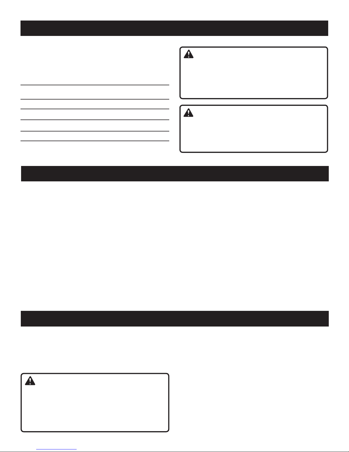
Check the work area before each use. Remove all objects
such as rocks, broken glass, nails, wire, or string which
can be thrown or become entangled in the machine.
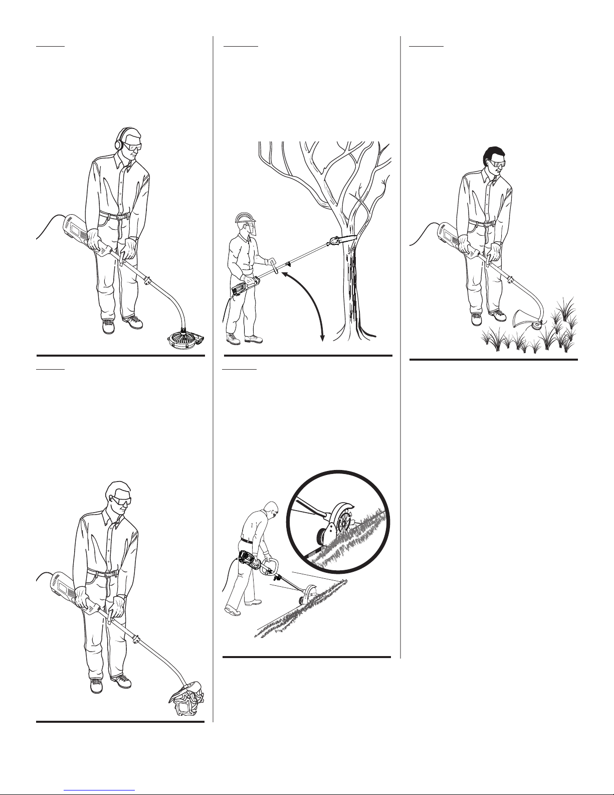
Use Safety Glasses – Always wear eye protection with
side shields marked to comply with ANSI Z87.1. Failure
to do so could result in objects being thrown into your
eyes, resulting in possible serious injury.
Always wear safety glasses with side shields. Everyday
glasses have only impact resistant lenses. They are NOT
safety glasses. Following this rule will reduce the risk of
eye injury. Use face mask if operation is dusty.
Dress Properly – Use rubber gloves and substantial
footwear is recommended when working outdoors. Wear
heavy long pants, long sleeves, boots, and gloves. Do not
wear loose-fitting clothing, short pants, sandals, jewelry
of any kind, or go barefoot.
Secure long hair above shoulder level to prevent
entanglement in moving parts.
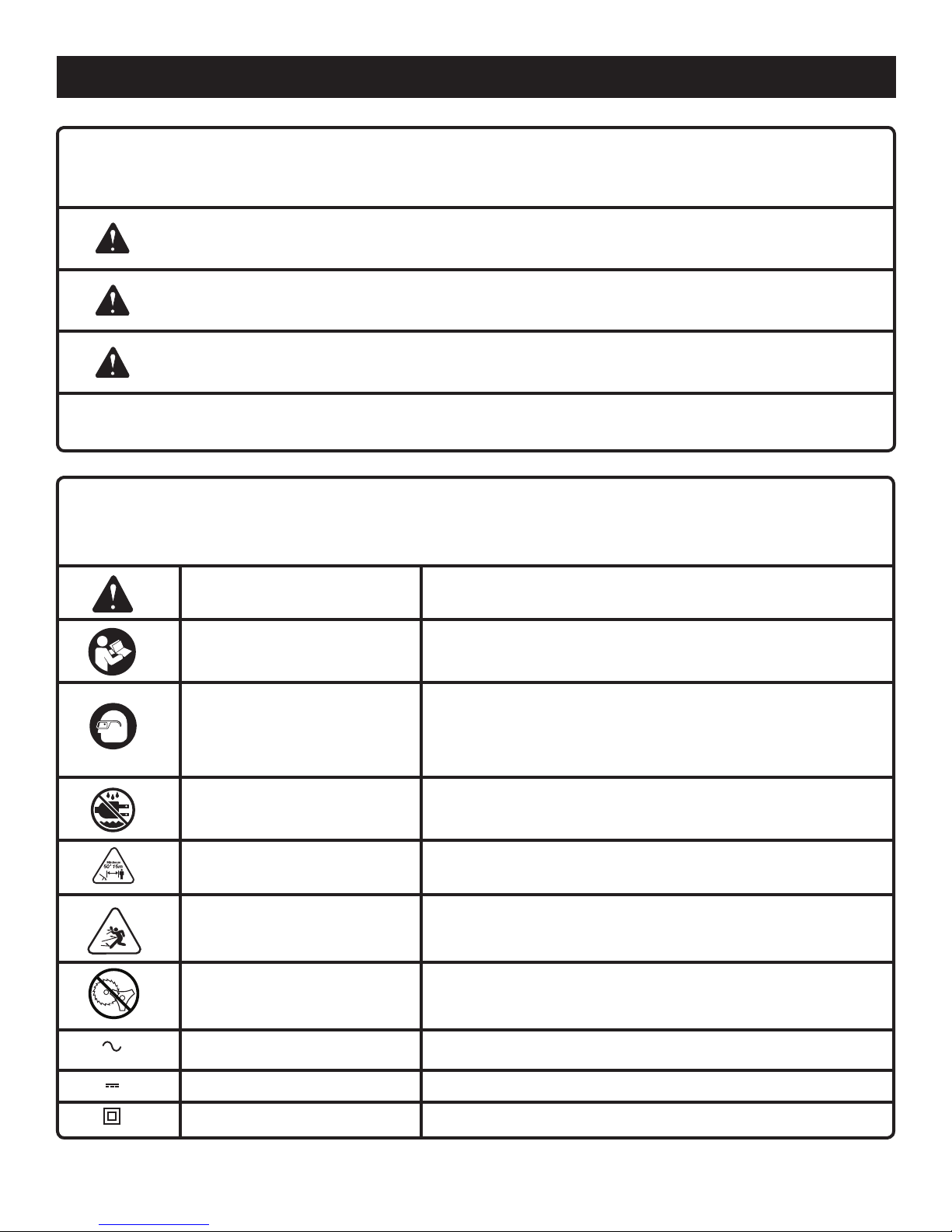
Keep children away – Keep all bystanders, children, and
pets at least 50 ft. away.
Stay alert – Do not operate this unit when you are tired,
ill, or under the influence of alcohol, drugs, or medication.
Do not operate in poor lighting.
Keep all parts of your body away from any moving part.
Do not operate power tools in explosive atmospheres,
such as in the presence of flammable liquids, gases, or
dust. Power tools create sparks which may ignite the dust
or fumes.
Toreducetheriskofelectric shock, this tool has a polarized
plug (one blade is wider than the other) and will require
the use of a polarized extension cord. The plug will fit into
a polarized extension cord only one way. If the plug does
not fit fully into the extension cord, reverse the plug. If the
plug still does not fit, obtain a correct polarized extension
cord. A polarized extension cord will require the use of a
polarized wall outlet. This plug will fit into the polarized
wall outlet only one way. If the plug does not fit fully into
the wall outlet, reverse the plug. If the plug still does not
fit, contact a qualified electrician to install the proper wall
outlet. Do not change the equipment plug, extension cord
receptacle, or extension cord plug in any way.
Avoidbody contact with grounded surfaces such aspipes,
radiators, ranges, and refrigerators. There is an increased
risk of electric shock if your body is grounded.
Avoid Dangerous Environments – Don’t expose power
tools to rain or wet conditions. Water entering a power
tool will increase the risk of electric shock.
Warning – To reduce the risk of electric shock - Use
outdoor extension cords marked W-A, W, SW-A, SOW-A,
STW-A, STOW-A, SJW-A, SJTW-A, or SJTOW-A. These
cords are rated for outdoor use and reduce the risk of
electric shock.
Ground Fault Circuit Interrupter (GFCI) protection should
be provided on the circuit(s) or outlet(s) to be used for the
gardening appliance. Receptacles are available having
built-in GFCI protection and may be used for this measure
of safety.
Use Right Appliance - Do not force tool. Use the correct
tool for your application. The correct tool will do the job
better and safer at the rate for which it is designed.
Do not operate the equipment while barefoot or when
wearing sandals or similar lightweight footwear. Wear
protective footwear that will protect your feet and improve
your footing on slippery surfaces.
Do not use on a ladder or unstable support. Stable footing
on a solid surface enables better control of the unit in
unexpected situations.
Do Not Overreach – Keep firm footing and balance.
Overreaching can result in loss of balance.
Avoid Unintentional Starting – Do not carry plugged in
appliance with finger on trigger. Be sure the switch trigger
is not engaged before plugging in.
Do not use tool if switch trigger does not turn it on or off.
Any tool that cannot be controlled with the switch trigger
is dangerous and must be repaired.
Disconnect Appliance – Remove appliance from power
source before storing, servicing, changing accessories
such as cutting line. Such preventive safety measures
reduce the risk of starting the tool accidentally.
Use only identical manufacturer’s replacement parts and
accessories. Use of any other parts may create a hazard
or cause product damage.
Maintain appliance with care – Replace string head if
cracked, chipped, or damaged in any way. Be sure the
string head is properly installed and securely fastened.
Keep cutting edge sharp and clean for best performance
and to reduce the risk of injury. Follow instructions for
lubricating and changing accessories. Inspect appliance
cord periodically, and if damaged, have it repaired by
an authorized service facility. Inspect extension cords
periodically and replace if damaged. Keep handles dry,

4 — English
IMPORTANT SAFETY INSTRUCTIONS
clean, and free from oil and grease. Failure to do so can
cause serious injury.
Make sure all guards, straps, deflectors and handles are
properly and securely attached.
Neveruse flailing devices, wire,orropeonanyattachment.
Use only the manufacturer’s replacement string in the
cutting head when using a string trimmer attachment.
Do not use any other cutting attachment, for example,
metal wire, rope, or the like. To install any other brand of
cutting head to the string trimmer can result in serious
personal injury.
Never operate unit without the grass deflector in place
and in good condition.
Check damaged parts – Before further use of the tool, a
guard or other part that is damaged should be carefully
checked to determine that it will operate properly and
perform its intended function. Check for alignment of
moving parts, binding of moving parts, breakage of parts,
mounting and any other conditions that may affect its
operation. A guard or other part that is damaged must
be properly repaired or replaced by an authorized service
center to avoid risk of personal injury.
Maintain a firm grip on both handles while trimming. Keep
string head below waist level. Never cut with the string
head located over 30 in. or more above the ground.
Store idle appliances - When not in use, power head
should be stored indoors in a dry, locked place out of
the reach of children. Do not allow appliance to be used
as a toy. Close attention is necessary when used near
children.
Extension Cord - Make sure your extension cord is in
good condition. When using an extension cord, be sure to
use one heavy enough to carry the current your product
will draw. A wire gauge size (A.W.G.) of at least 14 is
recommended for an extension cord 50 feet or less in
length. A cord exceeding 100 feet is not recommended.
If in doubt, use the next heavier gauge. The smaller the
gauge number, the heavier the cord. An undersized cord
will cause a drop in line voltage resulting in loss of power
and overheating.
Turn off controls before unplugging.
Keep the air vents clean and free of debris to avoid
overheating the motor. Clean after each use.
Stop the unit and disconnect the power source when not
in use. Carry the unit with the motor stopped.
Store unplugged and out of the reach of children when
not in use.
Do not hang unit so that the switch trigger is depressed.
Do not use multiple cords.
Do not abuse the cord – Never carry the unit by the
extension cord or yank extension cord to disconnect unit.
Keep the cord clear of operator and obstacles at all times.
Do not expose cords to heat, oil, water, or sharp edges.
Do not handle plug with wet hands.
If the power supply cord is damaged, it must be replaced
only by the manufacturer or by an authorized service
center to avoid risk.
Ifappliance is not working as it should ,has been dropped,
damaged, dropped into water, return it to service center.
Don’t grasp the exposed cutting blades or cutting edges
when picking up or holding the appliance.
Don’t Force Appliance – It will do the job better and with
less likelihood of a risk of injury at the rate for which it
was designed.
Danger – Risk of Cut – Keep Hands Away From Blades –
Keep both hands on handles when power is on. Do not
attempt to remove cut material nor hold material to be
cut when blades are moving. Make sure trimmer switch
is off when clearing jammed material from blades.
Caution – blades coast after turn off.
When operating the trimmer keep extension cord behind
trimmer.
Do not put any objects into openings. Do not use with
any openings blocked, keep free of dust, lint, hair and
anything that may reduce air flow.
Save these instructions. Refer to them frequently and
use them to instruct others who may use this power tool.
If you loan someone this power tool, loan them these
instructions also.
ADDITIONAL SPECIFIC SAFETY RULES CAN BE FOUND IN THE
APPLICABLE ATTACHMENT’S OPERATOR’S MANUAL

5 — English
SYMBOLS
The following signal words and meanings are intended to explain the levels of risk associated with this product.
SYMBOL SIGNAL MEANING
DANGER: Indicates an imminently hazardous situation, which, if not avoided, will result
in death or serious injury.
WARNING: Indicates a potentially hazardous situation, which, if not avoided, could result
in death or serious injury.
CAUTION: Indicates a potentially hazardous situation, which, if not avoided, may result in
minor or moderate injury.
NOTICE: (Without Safety Alert Symbol) Indicates important information not related to an
injury hazard, such as a situation that may result in property damage.
Keep Bystanders Away Keep all bystanders at least 50 ft. away.
Do not expose to rain or use in damp locations.
Wet Conditions Alert
To reduce the risk of injury, user must read and understand
operator’s manual before using this product.
Read Operator’s Manual
Safety Alert Indicates a potential personal injury hazard.
Ricochet Thrown objects can ricochet and result in personal injury or
property damage.
No Blade Do not install or use any type of blade on a product displaying
this symbol.
Eye Protection
Always wear eye protection with side shields marked to comply with
ANSI Z87.1. Hearing and/or head protection may also be required
depending on the type of attachment used and as prescribed in
the attachment’s Operator’s Manual.
Some of the following symbols may be used on this product. Please study them and learn their meaning. Proper inter-
pretation of these symbols will allow you to operate the product better and safer.
SYMBOL NAME DESIGNATION/EXPLANATION
Type of current
Type or a characteristic of current
Double-insulated construction
Class II Construction
Direct Current
Alternating Current

6 — English
SYMBOLS
ELECTRICAL
DOUBLE INSULATION
Double insulation is a concept in safety in electric power
tools, which eliminates the need for the usual three-
wire grounded power cord. All exposed metal parts are
isolated from the internal metal motor components with
protecting insulation. Double insulated tools do not need
to be grounded.
WARNING:
The double insulated system is intended to protect
the user from shock resulting from a break in the tool’s
internal insulation. Observe all normal safety precautions
to avoid electrical shock.
NOTE: Servicing of a product with double insulation requires
extreme care and knowledge of the system and should
be performed only by a qualified service technician. For
service, we suggest you return the product to your near-
est authorized service center for repair. Always use original
factory replacement parts when servicing.
Frequency (cycles per second)
Power
Time
min Minutes
WWatt
Hz Hertz
Some of the following symbols may be used on this product. Please study them and learn their meaning. Proper inter-
pretation of these symbols will allow you to operate the product better and safer.
SYMBOL NAME DESIGNATION/EXPLANATION
ELECTRICAL CONNECTION
This product has a precision-built electric motor. It should
be connected to a power supply that is 120 V, AC only
(normal household current), 60 Hz. Do not operate this
product on direct current (DC). A substantial voltage drop
will cause a loss of power and the motor will overheat. If
the product does not operate when plugged into an outlet,
double-check the power supply.
GFCI
Ground Fault Circuit Interrupter (GFCI) protection should be
provided on the circuit(s) or outlet(s) to be used for the prod-
uct. Receptacles are available having built-in GFCI protection
and may be used for this measure of safety.
EXTENSION CORDS
When using a power tool at a considerable distance from
a power source, be sure to use an extension cord that has
the capacity to handle the current the product will draw. An
undersized cord will cause a drop in line voltage, resulting in
overheating and loss of power. Use the chart to determine
the minimum wire size required in an extension cord. Only
round jacketed cords listed by Underwriter’s Laboratories
(UL) should be used.
Voltage
VVolts
Current
AAmperes

7 — English
ELECTRICAL
WARNING:
Keep the extension cord clear of the working area.
Position the cord so that it will not get caught on
lumber, tools, or other obstructions while you are working
with a power tool. Failure to do so can result in serious
personal injury.
WARNING:
Check extension cords before each use. If damaged
replace immediately. Never use the product with a
damaged cord since touching the damaged area could
cause electrical shock resulting in serious injury.
When working outdoors with a product , use an extension
cord that is designed for outside use. This type of cord is
designated with “W-A” or “W” on the cord’s jacket.
Before using any extension cord, inspect it for loose or
exposed wires and cut or worn insulation.
**Ampere rating (on product data plate)
0-2.0 2.1-3.4 3.5-5.0 5.1-7.0 7.1-12.0 12.1-16.0
Cord Length Wire Size (A.W.G.)
25’16 16 16 16 14 14
50’16 16 16 14 14 12
100’16 16 14 12 10 —
**Used on 12 gauge - 20 amp circuit.
NOTE: AWG = American Wire Gauge
FEATURES
PRODUCT SPECIFICATIONS
Operating RPM.................................................................................................................................................10,745 (RPM)
Input ....................................................................................................................................120 V, 60 Hz, AC only, 10 Amps
KNOW YOUR PRODUCT
See Figure 1.
The safe use of this product requires an understanding of
the information on the tool and in this operator’s manual
as well as a knowledge of the project you are attempting.
Before use of this product, familiarize yourself with all oper-
ating features and safety rules, in both this manual and the
operator’s manuals for all attachments that your are using
with this power head.
CORD RETAINER
The cord retainer helps prevent accidental unplugging of
the extension cord.
LOCK-OUT BUTTON
The lock-out button reduces the possibility of accidental
starting.
FRONT HANDLE
The power head is equipped with a front handle assembly
for ease of operation and to prevent loss of control.
ASSEMBLY
UNPACKING
This product requires assembly.
Carefully remove the product and any accessories from
the box. Make sure that all items listed in the packing list
are included.
WARNING:
Do not use this product if any parts on the packing list
are already assembled to your product when you unpack
it. Parts on this list are not assembled to the product by
the manufacturer and require customer installation. Use
of a product that may have been improperly assembled
could result in serious personal injury.
Inspect the product carefully to make sure no breakage
or damage occurred during shipping.
Donot discardthepackingmaterial until you have carefully
inspected and satisfactorily operated the product.
If any parts are damaged or missing, please call
1-800-860-4050 for assistance.
PACKING LIST
Power Head
Front Handle with Hardware
Operator’s Manual

8 — English
ASSEMBLY
WARNING:
If any parts are damaged or missing do not operate this
product until the parts are replaced. Use of this product
with damaged or missing parts could result in serious
personal injury.
WARNING:
Do not attempt to modify this product or create acces-
sories not recommended for use with this product. Any
such alteration or modification is misuse and could result
in a hazardous condition leading to possible serious
personal injury.
WARNING:
Do not connect to power supply until assembly is com-
plete. Failure to comply could result in accidental starting
and possible serious personal injury.
INSTALLING AN ATTACHMENT TO THE POWER
HEAD
See Figure 2.
WARNING:
Read and understand entire Operator’s Manual for each
optional attachment used on this power head and fol-
low all warnings and instructions. Failure to follow all
instructions may result in electric shock, fire and/or seri-
ous personal injury.
WARNING:
This electric power head is designed to be only used
with the attachment models that are specified in this
Operator’s Manual. It is not designed to be used with
brush cutters or other attachment models. Use of other
attachments could cause serious personal injuries or
property damage.
WARNING:
Never install, remove, or adjust any attachment while
power head is running. Failure to stop the motor can
cause serious personal injury. Never operate power head
without an attachment.
This electric power head may be used with only the following
Ryobi Expand-It attachments:
RY15518 Edger
RY15520 Pruner
RY15523 Straight Shaft String Trimmer
RY15525 Curved Shaft String Trimmer
RY15550 Tiller
RY15519 Blower
NOTE: When using string trimmer attachments, use only
.080 in. diameter line.
The attachment connects to the power head by means of
a coupler device.
Unplug the power head.
Loosen the knob on the coupler and remove the hanger
cap from the attachment.
Push in the button located on the attachment shaft. Align
thebutton with the guiderecessonthe power head coupler
and slide the two shafts together. Rotate the attachment
shaft until the button locks into the positioning hole.
NOTE: If the button does not release completely in the
positioning hole, the shafts are not locked into place.
Slightly rotate from side to side until the button is locked
into place.
Tighten the knob securely.
WARNING:
Be certain the knob is fully tightened before operating
equipment; check it periodically for tightness during use
to avoid serious personal injury.
ATTACHING THE FRONT HANDLE
See Figure 3.
Unplug the power head.
Press the front handle onto the power head shaft so that
the handle is angled toward the rear handle.
Place the front handle along the power head shaft to a
position that allows for comfortable operation.
Slide the bolt through the holes in the front handle.
Slide the washer onto the bolt.
Place the wing nut onto the bolt and tighten the wing nut
securely.

9 — English
LOCK-OUT BUTTON
See Figure 6.
The lock-out button reduces the possibility of accidental
starting. The lock-out button is located on the handle above
the switch trigger. The lock-out button must be depressed
before you pull the switch trigger. The lock resets each time
the trigger is released.
STARTING AND STOPPING THE POWER HEAD
See Figure 6.
To start the power head: Depress the lock-out button and
squeeze the switch trigger.
To stop the power head: Release the switch trigger.
OPERATING THE POWER HEAD
See Figures 7 - 13.
WARNING:
Motor housing may become hot during operation. Do not
rest or place your arm, hand, or any body part against
the motor housing during operation. Only hold the unit
as shown in figures 7 - 13 (depending on attachment
used) during trimmer operation with all body parts clear of
motor housing (or as shown in the applicable attachment
Operator’s Manual). Extended contact with the motor
housing may result in burns or other injuries.
WARNING:
Always position the unit on the operator’s right side. The
use of the unit on the operator’s left side will expose the
user to hot surfaces and can result in possible burn injury.
WARNING:
To avoid burns from hot surfaces, never operate unit with
the bottom of the motor above waist level.
Hold the power head with your right hand on the rear handle
and your left hand on the front handle. Keep a firm grip with
both hands while in operation. Power head should be held at
a comfortable position with the rear handle about hip height.
Always operate power head at full throttle. If debris becomes
wrapped around the attachment, RELEASE THE SWITCH
TRIGGER, unplug the unit, and remove the debris.
WARNING:
Read and understand entire Operator’s Manual for each
optional attachment used on this power head and fol-
low all warnings and instructions. Failure to follow all
instructions may result in electric shock, fire and/or seri-
ous personal injury.
WARNING:
Do not allow familiarity with product to make you care-
less. Remember that a careless fraction of a second is
sufficient to inflict serious injury.
WARNING:
Always wear eye protection with side shields marked
to comply with ANSI Z87.1. Hearing and/or head
protection may also be required depending on the type
of attachment used and as prescribed in the attachment’s
Operator’s Manual. Failure to do so could result in objects
being thrown into your eyes and other possible serious
injuries.
WARNING:
Do not use any attachments or accessories not recom-
mended by the manufacturer of this product. The use of
attachments or accessories not recommended can result
in serious personal injury.
CONNECTING TO POWER SUPPLY
See Figure 4 -5.
The power head is designed with a cord retainer that pre-
vents the extension cord from being pulled loose while using.
Form a loop with the end of the extension cord.
Insert loop portion of extension cord through opening in
the bottom of the rear handle and place over cord retainer.
Slowly pull loop against cord retainer until the slack is
removed.
Plug power head into extension cord.
NOTE: Failure to remove all excess cord slack from extension
cord retainer could result in plug loosening from receptacle.
OPERATION

10 — English
WARNING:
When servicing, use only identical replacement parts.
Use of any other parts may create a hazard or cause
product damage.
WARNING:
Always wear eye protection with side shields marked to
comply with ANSI Z87.1, along with hearing protection.
Head protection may also be required depending on the
type of attachment used and as prescribed in the attach-
ment’s Operator’s Manual. Failure to do so could result in
objects being thrown into your eyes and other possible
serious injuries.
WARNING:
Before inspecting, cleaning, or servicing the machine,
shut off motor, wait for all moving parts to stop, and
disconnect extension cord. Failure to follow these
instructions can result in serious personal injury or prop-
erty damage.
GENERAL MAINTENANCE
Avoid using solvents when cleaning plastic parts. Most
plastics are susceptible to damage from various types of
commercial solvents and may be damaged by their use.
Use clean cloths to remove dirt, dust, lubricant, grease, etc.
MAINTENANCE
WARNING:
Donotatany timelet brakefluids,gasoline,petroleum-based
products, penetrating lubricants, etc., come in contact
with plastic parts. Chemicals can damage, weaken or
destroy plastic which may result in serious personal injury.
You can often make adjustments and repairs described
here. For other repairs, have the power head serviced by
an authorized service dealer.
CLEANING THE POWER HEAD
Stop the motor and disconnect from power supply.
Clean dirt and debris from the power head using a damp
cloth with a mild detergent.
NOTE: Do not use any strong detergents on the plastic
housing or the handle. They can be damaged by certain
aromatic oils such as pine and lemon, and by solvents
such as kerosene.
STORING THE POWER HEAD
Clean all foreign material from the product.
Store it in a well-ventilated place that is inaccessible to
children.
Keep away from corrosive agents such as garden
chemicals and de-icing salts.
TROUBLESHOOTING
PROBLEM CAUSE SOLUTION
Motor fails to start when switch trig-
ger is depressed.
Power cord is not plugged in or con-
nection is loose.
Household circuit breaker is tripped.
Plug in the power cord.
Check circuit breaker.
OPERATION
WARNING:
Always hold the power head away from the body keep-
ing clearance between the body and the product. Any
contact with the attachment cutting head can result in
burns and/or other serious personal injury.
WARNING:
Extreme care must be taken when using a blade attachment
to ensure safe operation. Read the safety information for safe
operation when using a blade attachment and refer to the
safety rules and instructions in your attachment manual.
Never use a brush cutter attachment with this electric
power head. Improper operation of a blade or any at-
tachment could result in serious injury.

11 — English
WARRANTY
LIMITED WARRANTY STATEMENT
Techtronic Industries North America, Inc., warrants to the
original retail purchaser that this RYOBI®brand outdoor
product is free from defect in material and workmanship
and agrees to repair or replace, at Techtronic Industries
North America, Inc.’s, discretion, any defective product
free of charge within these time periods from the date of
purchase.
Three years if the product is used for personal, family
or household use;
90 days, if used for any other purpose, such as
commercial or rental.
This warranty extends to the original retail purchaser
only and commences on the date of the original retail
purchase.
Any part of this product found in the reasonable judgment
of Techtronic Industries North America, Inc. to be defective
in material or workmanship will be repaired or replaced
without charge for parts and labor by an authorized service
center for RYOBI®brand outdoor products (Authorized
Ryobi Service Center).
Theproduct,including any defective part, must be returned
to an authorized Ryobi service center within the warranty
period.The expense of delivering the productto the service
center for warranty work and the expense of returning it
back to the owner after repair or replacement will be paid
by the owner. Techtronic Industries North America, Inc.’s,
responsibility in respect to claims is limited to making the
required repairs or replacements and no claim of breach of
warranty shall be cause for cancellation or rescission of the
contractof sale of anyRYOBI®brand outdoor product.Proof
of purchase will be required by the dealer to substantiate
any warranty claim. All warranty work must be performed
by an authorized service dealer.
This warranty is limited to ninety (90) days from the date
of original retail purchase for any RYOBI®brand outdoor
product that is used for rental or commercial purposes, or
any other income-producing purpose.
This warranty does not cover any product that has been
subject to misuse, neglect, negligence, or accident, or that
has been operated in any way contrary to the operating
instructions as specified in this operator’s manual. This
warranty does not apply to any damage to the product that
is the result of improper maintenance or to any product
that has been altered or modified. The warranty does not
extend to repairs made necessary by normal wear or by the
use of parts or accessories which are either incompatible
with the RYOBI®brand outdoor product or adversely affect
its operation, performance, or durability. In addition, this
warranty does not cover:
A. Tune-ups – Spark Plugs, Carburetor, Carburetor
Adjustments, Ignition, Filters
B. Wear items – Bump Knobs, Outer Spools, Cutting
Lines, Inner Reels, Starter Pulleys, Starter Ropes, Drive
Belts, Tines, Felt Washers, Hitch Pins, Mulching Blades,
Blower Fans, Blower and Vacuum Tubes, Vacuum Bag
and Straps, Guide Bars, Saw Chains
Techtronic Industries North America, Inc., reserves the
right to change or improve the design of any RYOBI®brand
outdoorproductwithout assuming any obligation to modify
any product previously manufactured.
ALL IMPLIED WARRANTIES ARE LIMITED IN DURATION
TO THE STATED WARRANTY PERIOD. ACCORDINGLY,
ANY SUCH IMPLIED WARRANTIES INCLUDING
MERCHANTABILITY, FITNESS FOR A PARTICULAR
PURPOSE, OR OTHERWISE, ARE DISCLAIMED
IN THEIR ENTIRETY AFTER THE EXPIRATION OF
THE APPROPRIATE THREE-YEAR OR NINETY-DAY
WARRANTY PERIOD. TECHTRONIC INDUSTRIES
NORTH AMERICA, INC.’S, OBLIGATION UNDER THIS
WARRANTYISSTRICTLY AND EXCLUSIVELY LIMITED TO
THE REPAIR OR REPLACEMENT OF DEFECTIVE PARTS
AND TECHTRONIC INDUSTRIES NORTH AMERICA,
INC., DOES NOT ASSUME OR AUTHORIZE ANYONE
TO ASSUME FOR THEM ANY OTHER OBLIGATION.
SOME STATES DO NOT ALLOW LIMITATIONS ON HOW
LONG AN IMPLIED WARRANTY LASTS, SO THE ABOVE
LIMITATION MAY NOT APPLY TO YOU. TECHTRONIC
INDUSTRIES NORTH AMERICA, INC., ASSUMES NO
RESPONSIBILITY FOR INCIDENTAL, CONSEQUENTIAL,
OR OTHER DAMAGES INCLUDING, BUT NOT LIMITED
TO, EXPENSE OF RETURNING THE PRODUCT TO AN
AUTHORIZED RYOBI SERVICE CENTER AND EXPENSE
OF DELIVERING IT BACK TO THE OWNER, MECHANIC’S
TRAVEL TIME, TELEPHONE OR TELEGRAM CHARGES,
RENTAL OF A LIKE PRODUCT DURING THE TIME
WARRANTY SERVICE IS BEING PERFORMED, TRAVEL,
LOSS OR DAMAGE TO PERSONAL PROPERTY, LOSS
OF REVENUE, LOSS OF USE OF THE PRODUCT, LOSS
OF TIME, OR INCONVENIENCE. SOME STATES DO NOT
ALLOWTHE EXCLUSION ORLIMITATION OFINCIDENTAL
OR CONSEQUENTIAL DAMAGES, SO THE ABOVE
LIMITATION OR EXCLUSION MAY NOT APPLY TO YOU.
This warranty gives you specific legal rights, and you may
also have other rights which vary from state to state.
This warranty applies toall RYOBI®brand outdoor products
manufacturedbyor for TechtronicIndustries NorthAmerica,
Inc., and sold in the United States and Canada.
To locate your nearest Authorized Ryobi Service Center,
dial 1-800-860-4050.

3 — Français
INSTRUCTIONS IMPORTANTES CONCERNANT LA SÉCURITÉ
AVERTISSEMENT !
Lire et veiller à bien comprendre toutes les instructions
avant d’utiliser ce produit. Le non-respect des instructions
ci-dessous peut entraîner une électrocution, un incendie et
des blessures graves. Ne pas utiliser l’outil sans sa garde
et sa poignée.
LIRE TOUTES LES INSTRUCTIONS
Pour travailler en toute sécurité, lire et veiller à bien com-
prendre toutes les instructions avant d’utiliser ce produit.
Respecter toutes les instructions de sécurité. Le non respect
des instructions de sécurité ci-dessous peut entraîner des
blessures graves.
Ne pas laisser des enfants ou personnes n’ayant pas reçu
une formation adéquate utiliser cet outil.
Déblayer la zone de travail avant chaque utilisation. La
débarrasser de tous les objets tels que cailloux, verre brisé,
clous, fils métalliques, cordes, etc. risquant d’être projetés
ou de se prendre dans la ligne de coupe ou la lame.
Porter des lunettes de sécurité – Toujours porter une pro-
tection oculaire avec écrans latéraux certifiée conforme à
la norme ANSI Z87.1. Si cette précaution n’est pas prise,
des objets peuvent être projetés dans les yeux et d’autres
lésions graves.
Toujoursporter des lunettes desécurité avec écrans latéraux.
Les lunettes de vue ordinaires sont munies seulement de
verres résistants aux impacts. Ce ne sont PAS des lunettes
de sécurité. Le respect de cette règle réduira les risques de
lésions oculaires.. Utiliser un masque si la tâche à accomplir
génère beaucoup de poussière.
S’habiller convenablement – les gants de caoutchouc
d’Usage et la chaussures substantielle sont recommandés
en travaillant dehors. Porter des pantalons longs, manches
longues, des chaussures de travail et des gants épais. Ne
pas porter de vêtements amples, shorts, bijoux quels qu’ils
soient, sandales et ne pas travailler pieds nus.
Attacher les cheveux longs pour les maintenir au-dessus
des épaules, afin qu’ils ne se prennent pas dans les pièces
en mouvement.
Tenir les enfants éloignés - Ranger les appareils qui ne sont
pas utilisés - Garder les badauds, enfants et animaux à une
distance de 15 m (50 pi) minimum.
Rester alerte - Ne pas utiliser ce taille-bordures en état de
fatigue, si l’on est souffrant ou sous l’influence de l’alcool,
de drogues ou de médicaments.
Ne pas fonctionner dans les pauvres allumant.
Garder toutes les parties du corps à l’écart des pièces en
mouvement.
Nepas utiliser d’outils électriques dans des atmosphèresex-
plosives, par exemple en présence de liquides, gaz ou pous-
sières inflammables. Les outils électriques produisent des
étincelles risquant d’enflammer les poussières ou vapeurs.
Pouréviter les risques de choc électrique, cet outil est équipé
d’une fiche polarisée (une broche est plus large que l’autre)
qui exige l’usage d’un cordon polarisé. Cette fiche ne peut
être branchée sur une prise polarisée que dans un sens. Si
la fiche ne peut pas être insérée dans la prise du cordon,
l’inverser. Si la fiche ne peut toujours pas être insérée, se
procurer un cordonpolariséapproprié.Une rallonge polarisée
exigera l’utilisation d’une prise de courant murale polarisée.
Cette fiche ne peut être branchée dans une prise polarisée
que dans un sens. Si la fiche ne peut pas être insérée à fond
dans la prise, l’inverser. Si elle ne peut toujours pas être
insérée, faire installer une prise adéquate par un électricien
qualifié. Ne jamais modifier la fiche de l’outil, ni la prise ou
la fiche du cordon prolongateur.
Éviter tout contact du corps avec des surfaces mises à la
terre, telles que tuyaux, radiateurs, cuisinières et réfrigéra-
teurs. Le risque de choc électrique est accru lorsque le corps
est mis à la terre.
Éviter les environnements dangereux - Ne pas exposer les
outils électriques à la pluie ou l’humidité. La pénétration
d’eau dans ces outils accroît le risque de choc électrique.
Avertissement – Pour réduire le risque d’un choc électrique
- Utiliser des cordons prolongateurs marqués W-A, W,
W-A, W, SW-A, SOW-A, STW-A, STOW-A, SJW-A, SJTW-
A, ou SJTOW-A. Ces cordons sont conçus pour l’usage
en extérieur et réduisent les risques de choc électrique.
Les circuits et prises sur lesquels cet outil est branché doi-
vent être protégés par un disjoncteur différentiel. Des prises
à disjoncteur différentiel sont en vente dans le commerce et
peuvent être utilisées à titre de sécurité.
Utiliser l’outil approprié - Ne pas forcer l’outil. Utiliser un
outil approprié pour le travail. Un outil approprié exécutera
le travail mieux et de façon moins dangereuse s’il fonctionne
dans les limites prévues.
Ne pas faire fonctionner l’équipement pied-nu ou en portant
des sandales ou des chaussures légères similaires. Porter
des chaussures de protection qui protègent vos pieds et
améliorent votre équilibre sur des surfaces glissantes.
Ne pas utiliser l’outil sur une échelle ou un support instable.
Une bonne tenue et un bon équilibre permettent de mieux
contrôler l’outil en cas de situation imprévue.
Ne pas travailler hors de portée - Se tenir bien campé et en
équilibre. Ne pas travailler hors de portée de l’outil.
Éviter une mise en marche accidentelle – Éviter les démar-
ragesaccidentels. S’assurerquela gâchette ducommutateur
n’est pas engagée avant de brancher l’outil.
Ne pas utiliser l’outil si le commutateur ne permet pas de le
mettre en marche et de l’arrêter. Tout outil qui ne peut pas
être contrôlé par son commutateur est dangereux et doit
être réparé.
Débrancher l’appareil – Retirer l’appareil de la source
d’alimentation avant d’entreposer, d’effectuer l’entretien
ou de changer les accessoires comme le fil de coupe. Ces
mesures de sécurité réduisent les risques de démarrage
accidental de l’outil.
Utiliser exclusivement des pièces de rechange et accessoire
d’origine. L’usage de toute autre pièce pourrait créer une
situation dangereuse ou endommager l’outil.
Assurer un entretien soigneux de l’appareil - Si la tête de
coupe est fendue, brisée ou endommagée de quelque façon
que ce soit, la remplacer. S’assurer que la tête de coupe ou

4 — Français
INSTRUCTIONS IMPORTANTES CONCERNANT LA SÉCURITÉ
la lame est correctement installée et solidement assujettie.
Conserver les tranchants affûtés et propres pour obtenir
un rendement optimal et réduire les risques de blessures.
Suivre les instructions fournies pour lubrifier l’outil et
changerles accessoires.Inspecter périodiquementle cordon
d’alimentation de l’appareil. Si ce cordon est endommagé,
le faire réparer dans un centre de service autorisé. Inspecter
régulièrementlescordonsprolongateurset les remplacers’ils
sont endommagés. Garder les poignées sèches, propres et
exemptes de dépôts d’huile ou de graisse. S’il ne le sont
pas, l’opérateur court des risques de blessures graves.
S’assurerquetous les dispositifsde protection,déflecteurs et
poignéessont correctementinstalléset solidementassujettis.
Ne jamais utiliser un dispositif, une corde ou un fil à fouetter
sur un accessoire.
Utiliser exclusivement des lignes de coupe d’origine
au moment d’utiliser un accessoire de taille bordures.
N’utiliser aucun autre accessoire de coupe par exemple,
un fil métallique, une corde ou un élément semblable. Le
fait d’installer une tête de coupe d’une autre marque sur le
taille-bordures peut entraîner des blessures graves.
Ne jamais utiliser l’outil si le déflecteur d’herbe n’est pas en
place et en bon état.
Vérifier les pièces endommagées – Quand un protecteur
ou une autre pièce a été endommagé(e), vérifier, avant de
continuer à utiliser l’outil, si cette pièce pourra encore fonc-
tionner normalement et remplir son rôle. Vérifier l’alignement
des pièces mobiles, détecter les pièces mobiles grippées
ou les pièces rompues, un assemblage déficient ou toute
autre condition pouvant affecter la sécurité d’utilisation. Un
protecteurouune autrepièce endommagé(e) doit êtreréparé
convenablementou remplacépar un centred’entretienagréé
afin d’éviter des blessures corporelles.
Tenir fermement les deux poignées pendant le travail. Tenir
la tête de coupe au-dessous du niveau de la taille. Ne jamais
tailler avec la tête de coupe à plus de 762 mm (30 po) du
sol.
Rangerles appareilsqui nesont pas utilisés- Quand pasdans
l’usage, taille-bordures à ligne devrait être emmagasiné à la
maison dans un sec, fermé à clef la remiser dans un endroit
inaccessible aux enfants. Cet appareil n’est pas un jouet.
Porter une attention particulière en présence d’enfants.
Cordonprolongateurs–S’assurerque lecordonprolongateur
esten bonétat. Si uncordonprolongateurest utilisé,s’assurer
que sa capacité est suffisante pour supporter le courant
de fonctionnement de l’outil. Un calibre de fil (A.W.G) d’au
minimum 14 est recommandé pour un cordon prolongateur
de 15 mètres (50 pi) maximum. En cas de doute, utiliser un
cordonducalibreimmédiatement supérieur. Moinsle numéro
de calibre est élevé, plus la capacité du fil est grande. Un
cordon de capacité insuffisante causerait une baisse de la
tension de ligne, entraînant une perte de puissance et une
surchauffe.
Si l’appareil n’est pas utilisé, mettre les commandes à la
position d’arrêt avant de le débrancher.
S’assurer que les évents d’aération sont propres et exempts
de débris afin d’éviter que le moteur ne surchauffe. Les
nettoyer après chaque utilisation
Arrêter l’outil et le débrancher de la source d’alimentation
lorsqu’il n’est pas utilisé. Attendre l’arrêt complet du moteur
avant de déplacer l’outil.
Ranger l’outil en s’assurant qu’il est débranché et qu’il est
hors de la portée des enfants quand la tondeuse n’est pas
utilisée.
Ne pas suspendre l’outil d’une façon qui enclencherait la
gâchette.
Ne pas utiliser plus d’un cordon.
Éviter de malmener le cordon. Ne jamais transporter l’outil
en le tenant par le cordon, ou tirer d’un coup sec sur celui-ci
pour débrancher l’outil.Tenir le cordon loin de l’utilisateur
et des obstacles en tout temps. Ne pas exposer le cordon
à la chaleur, à l’huile, à l’eau ou à des arêtes tranchantes.
Ne pas manipuler la fiche avec les mains mouillées.
Si le cordon d’alimentation est endommagé, il doit être
remplacé uniquement pas le fabricant ou par un centre de
réparation agréé pour éviter tout risque.
Si l’appareil ne fonctionne pas correctement, s’il a été
échappé, s’il est endommagé ou s’il est tombé dans l’eau,
envoyez le au centre de réparations.
Nepas empoigner les lames ou les tranchantspour ramasser
ou tenir l’appareil.
Ne pas forcer l’appareil – Il sera plus efficace et présentera
moins de risques de blessures s’il est utilisé dans les limites
de ses spécifications.
Danger – Risque de coupure – Garder les mains à l’écart des
lames– Garderles deux mains sur les poignéeslorsque l’outil
est sous tension. Ne pas essayer de tenir les branchettes
à couper ou de les retirer quand elles l’ont été lorsque les
lames sont en mouvement. S’assurer que l’interrupteur du
taille-haie est en position d’arrêt avant de tenter de retirer
les débris coincés des lames.
Attention – les lames poursuivent leur mouvement après la
mise hors tension.
Garder le cordon prolongateur derrière l’outil pendant qu’il
fonctionne.
Ne placer aucun objet dans les ouvertures. Ne pas utiliser
le produit si l’une ou l’autre des ouvertures est obstruée.
Enlever toute la poussière, toutes les peluches et tous les
cheveux, ou tout autre élément pouvant réduire la circulation
de l’air.
Conserverces instructions. Lesconsulter fréquemment et les
utiliser pour instruire les autres utilisateurs éventuels. Si cet
outil est prêté, il doit être accompagné de ces instructions.
CONSULTER LE MANUEL D’UTILISATION DE L’ACCESSOIRE EN QUESTION AFIN DE
PRENDRE CONNAISSANCE DES RÈGLES DE SÉCURITÉ SUPPLÉMENTAIRES

5 — Français
SYMBOLES
Ne laisser personne s’approcher Garder les badauds à une distance de 15 m (50 pi) minimum.
Ne pas exposer à la pluie ou l’humidité.
Avertissement concernant
l’humidité
Pour réduire les risques de blessures, l’utilisateur doit lire et
veiller à bien comprendre le manuel d’utilisation avant d’utiliser
ce produit.
Lire le manuel d’utilisation
Symbole d’alerte
de sécurité Indique un risque de blessure potentiel.
Ricochet Les objets projetés peuvent ricocher et infliger des blessures ou
causer des dommages matériels.
Ne pas utiliser de lame Ne pas utiliser de lame sur cet outil.
Protection oculaire
Toujours porter une protection oculaire avec écrans latéraux cer-
tifiée conforme à la norme ANSI Z87.1. Selon le type d’accessoire
utilisé et comme il est indiqué dans le manuel d’utilisation de
l’accessoire en question, un casque de protection ou une protec-
tion auditive peut être nécessaire.
Certains des symboles ci-dessous peuvent être utilisés sur le produit. Veiller à les étudier et apprendre leur signification
pour assurer la sécurité d’utilisation.
SYMBOLE NOM EXPLICATION
Les termes de mise en garde suivants et leur signification ont pour but d’expliquer le degré de risques associé à l’utilisation
de ce produit.
SYMBOLE SIGNAL SIGNIFICATION
DANGER : Indique une situation extrêmement dangereuse qui, si elle n’est pas évitée,
aura pour conséquences des blessures graves ou mortelles.
AVERTISSEMENT : Indique une situation potentiellement dangereuse qui, si elle n’est pas évitée,
pourrait entraîner des blessures graves ou mortelles.
ATTENTION : Indique une situation potentiellement dangereuse qui, si elle n’est pas évitée,
pourraît entraîner des blessures légères ou de gravité modérée.
AVIS :
(Sans symbole d’alerte de sécurité) Indique une information importante
ne concernant pas un risque de blessure comme une situation pouvant
occasionner des dommages matériels.
Tension
VVolts
Type de courant
Type de courant
Construction à double isolation
Outil de la classe II
Courant continu
Courant alternatif

6 — Français
SYMBOLES
CARACTÉRISTIQUES ÉLECTRIQUES
DOUBLE ISOLATION
La double isolation est un dispositif de sécurité utilisé sur
les outils à moteur électriques, éliminant le besoin de cor-
don d’alimentation habituel à trois fils avec terre. Toutes les
pièces métalliques exposées sont isolées des composants
internes du moteur par l’isolation protectrice. Les outils à
double isolation ne nécessitent pas de mise à la terre.
AVERTISSEMENT :
Le système à double isolation est conçu pour protéger
l’utilisateur contre les chocs électriques causés par une
rupture de l’isolation interne de l’outil. Prendre toutes les
précautions de sécurité normales pour éviter les chocs
électriques.
NOTE : La réparation d’un outil à double isolation exigeant
des précautions extrêmes ainsi que la connaissance du
système, elle ne doit être confiée qu’à un réparateur qualifié.
En ce qui concerne les réparations, nous recommandons de
confier l’outil au centre de réparations le plus proche. Utiliser
exclusivement des pièces d’origine pour les réparations.
Intensité
Fréquence (cycles par seconde)
Puissance
Temps
min Minutes
WWatt
Hz Hertz
AAmpères
Certains des symboles ci-dessous peuvent être utilisés sur le produit. Veiller à les étudier et apprendre leur signification
pour assurer la sécurité d’utilisation.
SYMBOLE NOM EXPLICATION
CONNEXIONS ÉLECTRIQUES
Cet outil est équipé d’un moteur électrique de précision. Elle
doit être branchée uniquement sur une alimentation 120 V,
60 Hz, c.a. (courant résidentiel standard). Ne pas utiliser
cet outil sur une source de courant continu (c.c.). Une chute
de tension importante causerait une perte de puissance et
une surchauffe du moteur. Si l’outil ne fonctionne pas une
fois branché, vérifier l’alimentation électrique.
GFCI
Les circuits et prises sur lesquels cet outil est branchédoivent
être protégés par un disjoncteur différentiel. Desprises à
disjoncteur différentiel sont en vente dans le commerce et
peuvent être utilisées à titre de sécurité.
CORDONS PROLONGATEURS
Lors de l’utilisation d’un outil électrique à grande distance
d’une prise secteur, veiller à utiliser un cordon prolongateur
d’une capacité suffisante pour supporter l’appel de courant
de l’outil. Un cordon de capacité insuffisante causerait une
baisse de la tension de ligne, entraînant une perte de puis-
sance et une surchauffe. Se reporter au tableau ci-dessous
pour déterminer le calibre minimum de fil requis pour un
cordon donné. Utiliser exclusivement des cordons à gaine
cylindrique homologués par Underwriter’s Laboratories (UL).

7 — Français
CARACTÉRISTIQUES ÉLECTRIQUES
AVERTISSEMENT :
Maintenir le cordon prolongateur à l’écart de la zone de
travail. Lors du travail avec un cordon électrique, placer le
cordon de manière à ce qu’il ne risque pas de se prendre
dans les pièces de bois, outils et autres obstacles. Ne
pas prendre cette précaution peut entraîner des blessures
graves.
AVERTISSEMENT :
Vérifier l’état des cordons prolongateurs avant chaque
utilisation. Remplacer immédiatement tout cordon
endommagé. Ne jamais utiliser un outil dont le cordon
d’alimentation est endommagé, car tout contact avec la
partie endommagée pourrait causer un choc électrique et
des blessures graves.
Pour le travail à l’extérieur, utiliser un cordon prolongateur
spécialement conçu à cet effet. Ce type de cordon porte
l’inscription « WA » ou « W »sur sa gaine.
Avant d’utiliser un cordon prolongateur, vérifier que ses fils
ne sont ni détachés ni exposés et que son isolation n’est ni
coupée, ni usée.
**Intensité nominale (sur la plaquette signalétique de l’outil)
0-2,0 2,1-3,4 3,5-5,0 5,1-7,0 7,1-12,0 12,1-16,0
Longueur Calibre de fil
du cordon (A.W.G.)
25´ 16 16 16 16 14 14
50´ 16 16 16 14 14 12
100´ 16 16 14 12 10 —
**Utilisé sur circuit de calibre 12 - 20 A
NOTE : AWG = American Wire Gauge
CARACTÉRISTIQUES
FICHE TECHNIQUE
Vitesse de rotation......................................................................................................................................................10 745 (RPM)
Alimentation...............................................................................................................................120 V, 60 Hz, c.a. seulement, 10 A
APPRENDRE À PRODUIT
Voir la figure 1.
L’utilisation sûre de ce produit exige une comprehension des
renseignements figurant sur l’outil et contenus dans le manuel
d’utilisation, ainsi qu’une bonne connaissance du projet
entrepris. Avant d’utiliser ce produit, se familiariser dans le
présent manuel et dans les manuels d’utilisation de tous les
accessoires employés avec ce bloc moteur.
RETENUE DE CORDON
Cette retenue est conçue pour empêcher le débranchement
accidentel du cordon d’alimentation.
BOUTON DE VERROUILLA GE
Ce moteur est équipé d’un bouton de verrouillage pour réduire
le risque de démarrage accidentel.
POIGNÉE AVANT
Le bloc moteur est conçue le l’ensemble poignée avant pour
faciliter l’utilisation et prévenir les pertes de contrôle.
ASSEMBLAGE
DÉBALLAGE
Ce produit nécessite l’assemblage.
Avec précaution, sortir le produit et les accessoires de la
boîte. S’assurer que toutes les pièces figurant sur la liste de
contrôle sont incluses.
AVERTISSEMENT :
Ne pas utiliser le produit si, en le déballant, vous constatez
que des éléments figurant dans la liste de contrôle
d’expédition sont déjà assemblés. Certaines pièces figurant
sur cette liste n’ont pas été assemblées par le fabricant et
exigent une installation. Le fait d’utiliser un produit qui a été
assemblé de façon inadéquate peut entraîner des blessures.
Examiner soigneusement le produit pour s’assurer que rien
n’a été brisé ou endommagé en cours de transport.
Ne pas jeter les matériaux d’emballage avant d’avoir
soigneusement examiné le produit et avoir vérifié qu’il
fonctionne correctement.
Si des pièces sont manquantes ou endommagées,
appeler le 1-800-860-4050.
LISTE DES PIÈCES
Bloc-moteur
Poignée avant avec quincaillerie
Manuel d’utilisation

8 — Français
ASSEMBLAGE
Cet ensemble moteur électrique ne peut être utilisé qu’avec
les accessoires Expand-It Ryobi suivants :
Coupe-bordures RY15518
Élagueuse RY15520
Taille-bordures à arbre droit RY15523
Taille-bordures à arbre courbe RY15525
Cultivateur RY15550
Soufflante RY15519
NOTE : Lors de l’utilisation un taille-bordure accessoire, uti-
liser uniquement des ligne de 2,03 mm (0,80 po) de diamètre.
L’accessoire se raccorde au bloc-moteur à l’aide d’un dis-
positif de couplage.
Débrancher le bloc-moteur.
Desserrer le bouton du coupleur et retirer le capuchon
de suspension de l’accessoire.
Appuyer sur le bouton se trouvant sur l’arbre de
l’accessoire. Aligner le bouton sur la rainure guide du
bloc-moteur et emboîter les deux arbres. Tourner l’arbre
de l’accessoire jusqu’à ce que le bouton s’enclenche
dans le trou de positionnement.
NOTE : Si le bouton ne s’engage pas complètement dans
le trou de positionnement, les tubes ne sont pas solide-
ment maintenus l’un dans l’autre. Tourner légèrement
les tube dans les deux sens jusqu’à ce que le bouton
s’engage complètement.
Serrer le bouton fermement.
AVERTISSEMENT :
S’assurer que le bouton est bien serré avant d’utiliser
l’outil et le vérifier de temps à autre pour éviter le risque
de blessures graves.
INSTALLATION DE LA POIGNÉE AVANT
Voir la figure 3.
Débrancher le bloc-moteur.
Placer la poignée sur le dessus de l’arbre supérieur en
veillant à ce qu’elle soit inclinée vers la poignée avant.
Positionner la poignée sur l’arbre supérieur de manière
à obtenir une position d’utilisation confortable.
SInsérer le boulon dans les trous de la poignée avant.
Installer la rondelle sur le boulon.
Installer l’écrou papillon sur le boulon et le serrer ferme-
ment.
AVERTISSEMENT :
Si des pièces manquent ou sont endommagées, ne pas
utiliser ce produit avant qu’elles aient été remplacées.
Le fait d’utiliser ce produit même s’il contient des pièces
endommagées ou s’il lui manque des pièces peut
entraîner des blessures graves.
AVERTISSEMENT :
Ne pas essayer de modifier ce produit ou de créer des
accessoires non recommandés pour la produit. De
telles altérations ou modifications sont considérées
comme un usage abusif et peuvent créer des conditions
dangereuses, risquant d’entraîner des blessures graves.
AVERTISSEMENT :
Ne pas brancher sur le secteur avant d’avoir terminé
l’assemblage. Le non-respect de cet avertissement
peut causer un démarrage accidentel, entraînant des
blessures graves.
INSTALLATION DE DE L’ACCESSOIRE DU
BLOC-MOTEUR
Voir la figure 2.
AVERTISSEMENT :
Lire et veiller à bien comprendre tout le manuel
d’utilisation de chaque accessoire facultatif employé avec
l’ensemble moteur et respecter tous les avertissements
et toutes les instructions. Le non-respect de l’ensemble
des instructions peut entraîner une décharge électrique,
un incendie et des blessures graves.
AVERTISSEMENT :
Cet ensemble moteur électrique est conçu pour être
utilisé uniquement avec des modèles d’accessoires qui
sont mentionnés dans le présent manuel d’utilisation.
Il n’est pas compatible avec des débroussailleuses ou
d’autres modèles d’accessoires. Le fait d’utiliser d’autres
accessoires peut entraîner des blessures graves ou des
dommages matériels.
AVERTISSEMENT :
Ne jamais installer, retrait ou ajuster un accessoire lorsque
le moteur tourne. Ceci pourrait causer des blessures
graves. Ne jamais faire fonctionner le bloc moteur si
aucun accessoire n’y est fixé.

9 — Français
BOUTON DE VERROUILLA GE
Voir la figure 6.
Le bouton de verrouillage réduit le risque de démarrage
accidentel. Ce bouton se trouve sur la poignée, au-dessus
de la gâchette. Le bouton de verrouillage doit être verrouillé
avant d’appuyer sur la gâchette. Le bouton se désengage
automatiquement lorsque la gâchette est relâchée.
DÉMARRAGE ET ARRÊT
Voir la figure 6.
Pour mettre le bloc-moteur en marche : Enfoncer le
bouton de verrouillage et appuyer sur la gâchette.
Pour arrêter le bloc-moteur : Relâcher la gâchette
UTILISATION DU BLOC-MOTEUR
Voir les figures 7 à 13.
AVERTISSEMENT :
Le logement du moteur peut devenir chaud pendant
l’utilisation du taille bordures à fil. Éviter de placer ou
d’appuyer le bras, la main ou toute autre partie du corps
contre le logement du moteur pendant l’utilisation du
taille bordures. Tenir l’outil uniquement dans la position
illustrée à la figures 7 à 13 (selon l’accessoire utilisé) en
s’assurant qu’aucune partie du corps ne se trouve à
proximité du logement du moteur. Un contact prolongé
avec le logement du moteur peut entraîner des brûlures
ou d’autres blessures.
AVERTISSEMENT :
Toujours tenir l’outil à sa droite. L’utilisation à gauche
exposerait l’utilisateur aux surfaces chaudes, créant ainsi
des risques de brûlures.
AVERTISSEMENT :
Pour éviter le contact avec les parties brûlantes, ne jamais
travailler avec le bas du moteur au-dessus du niveau de
la taille.
Tenir le bloc-moteur avec la main droite sur la poignée arrière
et la main gauche sur la poignée avant. Garder une prise
ferme sur les deux poignées pendant le fonctionnement. Le
bloc-moteur doit être tenu dans une position confortable, la
poignée arrière se trouvant à peu près à hauteur de la taille.
Toujours faire fonctionner le bloc moteur à pleine puissance.
Si des débris s’enroulent autour de l’accessoire, ARRÊTER
LE MOTEUR, débrancher le fil de la bougie et retirer les
débris.
AVERTISSEMENT :
Lire et veiller à bien comprendre tout le manuel
d’utilisation de chaque accessoire facultatif employé avec
l’ensemble moteur et respecter tous les avertissements
et toutes les instructions. Le non-respect de l’ensemble
des instructions peut entraîner une décharge électrique,
un incendie et des blessures graves.
AVERTISSEMENT :
Ne pas laisser la familiarité avec le produit faire oublier
la prudence. Ne pas oublier qu’une fraction de seconde
d’inattention peut entraîner des blessures graves.
AVERTISSEMENT :
Toujours porter une protection oculaire avec écrans
latéraux certifiée conforme à la norme ANSI Z87.1
protection auditive. Selon le type d’accessoire utilisé
et comme il est indiqué dans le manuel d’utilisation
de l’accessoire en question, un casque de protection
et un protection auditiva peut être nécessaire. Si cette
précaution n’est pas prise, des objets peuvent être
projetés dans les yeux et d’autres lésions graves.
AVERTISSEMENT :
Ne pas utiliser d’outils ou accessoires non recommandés
pour cet outil. L’utilisation de pièces et accessoires non
recommandés peut entraîner des blessures graves.
CONNEXION SUR UNE PRISE SECTEUR
Voir les figures 4 -5.
L’ensemble moteur comprend une retenue de cordon qui
empêche le cordon prolongateur d’être débranché de l’outil
pendant l’usage.
Former une boucle à l’extrémité du cordon prolongateur.
Insérer la partie boucle du cordon prolongateur dans
l’ouverture du côté de la poignée arrière et placer sur
retenue de cordon.
Tirer lentement la boucle contre retenue de cordon pour
le tendre.
Brancher le cordon prolongateur dans la bloc-moteur.
NOTE : Ne pas tendre le cordon prolongateur sur son arrim-
age peut permettre au cordon de se débrancher de la prise.
UTILISATION
Table of contents
Languages:
Other Ryobi Power Tools manuals

Ryobi
Ryobi RT601W User manual

Ryobi
Ryobi RY40006VNM User manual

Ryobi
Ryobi JS550L User manual

Ryobi
Ryobi RRT4 User manual

Ryobi
Ryobi P738 User manual

Ryobi
Ryobi AirStrike R18ST User manual

Ryobi
Ryobi RDP102L User manual

Ryobi
Ryobi RRW18X User manual

Ryobi
Ryobi OLP18 User manual

Ryobi
Ryobi RY18PCA User manual