Safco 5330 User manual

A
B
C
D
E
F
G
H
I
J
K
L
M
N
O
P
Q
R
S
Base Plate 1 5330-07
Swivel Caster 2 5330-26
Thick Bolt 16 5330-22
Large Washer 16 5330-21
Large Nut 16 5330-24
Fixed Caster 2 5330-25
End Panel With Holes 1 5330-11
End Panel Without Holes 1 5330-01
U-Brace 2 5330-02
Shelf 2 5330-03
Side Rail 4 5330-04
Locking Plug 2 5330-09
End Cap 1 5330-05
Tray/Handle 1 5330-06
Small Washer 10 5330-31
Small Nut 6 5330-29
Long Thin Bolt 2 5330-23
Bracket 2 5330-28
Short Thin Bolt 2 5330-27
Q
Q
Q
Q
Q
Q
Q
Q
Q
Q
Q
Q
Q
Q
Q
Q
Q
Q
Q
MODEL
NUMBER 5330
5330-37: 1 of 4; Rev. 1: 10/01
2-Shelf Utility Cart
Safco Products Company, New Hope, MN 55428
At one end of the A Base Plate, install the two B
Swivel Casters using C Thick Bolts, D Large
Washers, and E Large Nuts. Tighten using a socket
wrench with a 14mm socket. At the other end, install
the two F Fixed Casters in the same manner.
1QQ
QQ
QSlide the keyhole slots of the G End Panel With
Holes onto the studs on the end of the A Base
Plate at which the handle will be attached, and
push the End Panel to the right to lock it in place.
Repeat with the H End Panel Without Holes at
the opposite end of the Base Plate.
2QQ
QQ
Q
ASSEMBLYINSTRUCTIONS
PART NO.
LETTER
CODE DESCRIPTION QTY.
PARTS LIST
ASSEMBLEDUNIT
Model 5330
TOOLS REQUIRED: Socket Wrench with 14mm
socket and 10mm socket (or open end wrenches
of that size),Phillips Screwdriver, Rubber Mallet
(or Hammer with Wood Block)
For questions or concerns, please call
Safco Consumer Hot Line: 1-800-664-0042
available Monday-Friday 8:30 AM to 4:30 PM
(CentralTime)
(English-speakingoperators)
QQ
QQ
Q
G
QQ
QQ
Q
C
A
QQ
QQ
Q
QQ
QQ
Q
D
QQ
QQ
Q
B
QQ
QQ
Q
E
QQ
QQ
Q
K
QQ
QQ
Q
L
QQ
QQ
Q
L
QQ
QQ
Q
N
QQ
QQ
Q
O
QQ
QQ
Q
P
QQ
QQ
Q
F
QQ
QQ
Q
QQ
QQ
QQQ
QQ
Q
QQ
QQ
Q
QQ
QQ
Q
A
QQ
QQ
Q
QQ
QQ
Q
C
QQ
QQ
Q
B
QQ
QQ
Q
D
QQ
QQ
Q
E
QQ
QQ
Q
F
QQ
QQ
Q
G
QQ
QQ
Q
A
KEYHOLE
SLOT
STUD
QQ
QQ
Q
QQ
QQ
Q
Q
QQ
QQ
Q
R
G has holes here;
H has no holes
QQ
QQ
Q
H
OR
QQ
QQ
Q
QQ
QQ
Q
QQ
QQ
Q
QQ
QQ
Q
M
QQ
QQ
Q
I
QQ
QQ
Q
J
QQ
QQ
Q
J
QQ
QQ
Q
H
QQ
QQ
Q
S

Assemble the two I U-Braces to form a rectangle,
snapping the two sections together at the overlapping
ends. IMPORTANT: find the word “TOP” molded into
the upper corners; this will identify the top of the
rectangle for the next step.
3
Place one of the J Shelves between the End
Panels, near the bottom of the U-Brace rectangle.
Press the Shelf down firmly, keeping it aligned over
the Base Plate. The last inch or so will require
tapping sharply with a rubber mallet (or a hammer
with a block of wood to protect the surface) at the
centerline of the Shelf to snap it over the U-Braces,
then at each of the four corners until the barb on the
Shelf corner enters the pocket in the End Panel (see
inset). HINT: Unsnap the top of the U-Braces so the
End Panels can spread slightly while doing this step,
then resnap the U-Braces.
5
Slide the assembled U-Brace rectangle (with the
top up) down into the channels in the End Panels.
There are keyhole slots and studs, similar to those
on the Base Plate and End Panels; as the rectangle
approaches the bottom of the channel, push the
End Panels together and continue sliding the
rectangle down all the way into the channel in the
Bottom Plate. If the side studs have properly
engaged the keyhole slots, the inside face of the
U-Brace rectangle will be flush with the End
Panel.
4
Tuck one end of one of the K Side Rails into the
bottom slot on one of the End Panels, along side
the Shelf, with the lip of the Side Rail up and
facing the Shelf. Tip the Side Rail up at an angle
as shown, and align its upper end with the slot on
the other End Panel. Tilt the Side Rail down into
position, so both ends are within their slots.
Repeat with another Side Rail on the other side of
theShelf.
6
5330-37: 2 of 4; Rev. 1: 10/01 Safco Products Company, New Hope, MN 55428
QQ
QQ
Q
QQ
QQ
Q
BARB
POCKET
QQ
QQ
Q
QQ
QQ
Q
K
LIPFACING
UP AND IN
SLOT
QQ
QQ
Q
I
QQ
QQ
Q
J

Place the second J Shelf over the top of the U-
Brace rectangle and between the End Panels, and
push down into position. Use the rubber mallet (or
hammer with a block of wood) at each corner as
before, to be sure the barbs engage the pockets.
IMPORTANT: after the corners are in place, hold the
center top of the Shelf down while tapping UP on the
U-Brace joint underneath, until the U-Braces snap into
the shelf (see inset).
7
Slide a L Locking Plug into the center channel of
one of the End Panels, with the slanted barb facing
the End Panel and the notched corner up and facing
the center of the cart. Push the Locking Plug down
between the End Panel and the Shelf, until the barb
snaps into place. Repeat at the other End Panel.
9
Slide the remaining two K Side Rails down into
the top slots of the End Panels.
8QQ
QQ
Q
Align the M Endcap over the H End Panel
Without Holes. Press firmly down until it
snaps into place (it may help to snap one end
first, then the other; or carefully use a rubber
mallet, or a hammer with a block of wood, to
tap it into place).
10
5330-37: 3 of 4; Rev. 1: 10/01 Safco Products Company, New Hope, MN 55428
QQ
QQ
Q
SLOT
QQ
QQ
Q
K
QQ
QQ
Q
QQ
QQ
Q
L
BARB
NOTCH
QQ
QQ
Q
QQ
QQ
Q
J
QQ
QQ
Q
QQ
QQ
Q
H (Without Holes!)
QQ
QQ
Q
M

Now attach the N Tray/Handle to the other G End
Panel With Holes, feeding the ends of the molded-in
bolts through the top holes in the End Panel and then
snapping it into place. NOTE: this WILL require a
rubber mallet or hammer with a block of wood; take
care not to mar or dent the plastic. It may also be
helpful to have a second person to hold the Tray/
Handle in position while doing this.
11
To provide a flat surface for transporting wide
objects or to allow sliding onto or off of the shelf,
lift the Side Rails slightly, pull outward slightly, and
drop the Side Rails down until they engage the lip
on the Shelf edge.
To form a basket for keeping objects on the Shelf,
reverse the procedure until the bottom edge of the
Side Rail is in the lip of the Shelf edge.
13
Place a O Small Washer over one of the bolts
from the Tray/Handle extending into the recess of
the End Panel, as shown, and add a P Small Nut,
finger-tight. Repeat with three more Small Washers
and Small Nuts on the remaining bolts. Now
tighten all nuts with a 10mm socket or open end
wrench. DO NOT OVER-TIGHTEN.
12 QQ
QQ
Q
14
5330-37: 4 of 4; Rev. 1: 10/01 Safco Products Company, New Hope, MN 55428
QQ
QQ
Q
QQ
QQ
Q
QQ
QQ
Q
N
QQ
QQ
Q
P
QQ
QQ
Q
O
FLAT TOP SHELF:
Top lip of side rail
in lip of shelf edge
BOX TOP SHELF:
Bottom lip of side rail
in lip of shelf edge
QQ
QQ
Q
QQ
QQ
Q
G
QQ
QQ
Q
PQQ
QQ
Q
O
QQ
QQ
Q
R
QQ
QQ
Q
Q
QQ
QQ
Q
O
HOLE
THREADED
INSERT
Attach the two R Brackets by inserting two Q Long
Thin Bolts through O Small Washers, then through
the Brackets, and through the holes in the side of the
G End Panel With Holes. Place another O Small
Washer over the end of both Long Thin Bolts, and
fasten loosely with P Small Nuts. Next insert a S
Short Thin Bolt through another O Small Washer and
then UPWARD through the top of one Bracket and
into the threaded insert on the bottom side of the
Tray/Handle. Tighten both long and short bolts, but
DO NOT OVERTIGHTEN. Repeat with the second
Bracket, toward the other side of the Tray/Handle.
QQ
QQ
QQQ
QQ
Q
QQ
QQ
Q
QQ
QQ
Q
QQ
QQ
QQQ
QQ
Q
QQ
QQ
Q
S
QQ
QQ
Q
QQ
QQ
Q

5330-37S: 1 of 2; Rev. 1: 10/01 Safco Products Company, New Hope, MN 55428
NUMÉRO
DE MODÈLE 5330
CHARRETTE DE L’UTILITÉ AVEC 2 ÉTAGÈRES
INSTRUCTIONS DE MONTAGE
Si vous avez des questions à poser ou des préoccupations à
exprimer, vous pouvez joindre la ligne téléphonique
d’assistance à la clientèle de Safco en composant
le 1-800-664-0042. La ligne est ouverte du lundi au vendredi,
entre 8 h et 16 h 30 (heure du Centre).
(Les standardistes sont d’expression anglaise.)
BasPanneau
1 5330-07
Roue pivotante 2 5330-26
Boulon épais 16 5330-22
Grande Rondelle 16 5330-21
Grande Écrou 16 5330-24
Roue stationnaire 2 5330-25
Panneau de la fin avec les Trous 1 5330-11
Panneau de la fin sans Trous 1 5330-01
U - Support 2 5330-02
Étagère 2 5330-03
Rail latéral 4 5330-04
Bouchon autofreiné 2 5330-09
Casquette de la fin 1 5330-05
plateau/poignéed’assistance
1 5330-06
Petite Rondelle 10 5330-31
Petite Écrou 6 5330-29
Long Boulon Mince 2 5330-23
Support 2 5330-28
Court Boulon Mince 2 5330-23
Q
Q
Q
Q
Q
Q
Q
Q
Q
Q
Q
Q
Q
Q
Q
Q
Q
Q
Q
A
B
C
D
E
F
G
H
I
J
K
L
M
N
O
P
Q
R
S
À une fin du Bas Panneau A , installez les deux Roues Pivotantes
B utiliser des Boulons Épais C , Grandes Rondelles D , et
Grandes Écrous E . Serrez utiliser une clef à tube avec une
14mm cavité. À l’autre fin, installez les deux Roues Fixes F dans
la même manière.
1QQ
QQ
Q
Glissez les trous de goujon du Panneau de la fin avec les Trous G
sur les bouton-pression sur la fin du Bas Panneau A à que le
manche sera attaché. Attachez en poussant le Panneau de la fin
à droite. Répétez avec le Panneau de la fin sans Trous H à la fin
opposée du Bas Panneau.
2QQ
QQ
Q
NODE PIÈCE
CODE
ALPHABÉTIQUE
DESCRIPTION QUANTITÉ
LISTE DES PIÈCES
ASSEMBLEDUNIT
Model 5330
OUTIL NÉCESSAIRE : Clef à tube avec 14mm cavité et
10mm cavité (ou clefs de la fin ouvertes de cette dimension),
Tournevis à pointe cruciforme n° 2, Maillet du Caoutchouc
(ou Martèle avec Bloc du Bois)
QQ
QQ
QQQ
QQ
QQQ
QQ
Q
QQ
QQ
QQQ
QQ
Q
KEYHOLE
SLOT STUD
QQ
QQ
Q
Assemblez-vous le deux U - Supports H former un rectangle.
Connectez les deux sections aux se chevauchant fins ensemble.
IMPORTANT : trouvez le mot “ que TOP ” a moulé dans les coins
supérieurs; cela identifiera la fin supérieure du rectangle pour la
prochaine instruction.
3
Placez une des Étagères I entre les Panneaux de la fin, proche
la fin inférieure de l’U - Support rectangle. Pressez l’Étagère vers
le bas fermement, en le gardant ont aligné sur le Bas Panneau.
Le pouce définitif ou donc exigera le tapoter puissant avec un
maillet du caoutchouc (ou un marteau avec un bloc de bois
protéger la surface) à la centre ligne de l’Étagère le connecter sur
l’U - Supports. Alors tapote chacun des quatre coins afin que le
barbillon sur le coin de l’Étagère entre dans la poche dans le
Panneau de la fin (voyez l’encart). L’ALLUSION : déconnectez la
fin supérieure de l’U - Supports afin que les Panneaux de la fin
puissent s’étendre pendant cette instruction légèrement, alors le
ré connecte l’U - Supports.
5
Glissez le rectangle s’assemblé de l’U - Supports (avec le mot
“ que TOP ” de bas en haut) en bas dans les canaux dans les
Panneaux de la fin. Il y a des trous de goujon et des boutons-
pression, semblable à ceux sur le Bas Panneau et Panneaux de la
fin. Poussez les Panneaux de la fin comme le rectangle ensemble
approche le fond du canal. Continuez à glisser le rectangle tout
le chemin dans le canal dans le Bas Panneau. Si les boutons-
pression latéraux ont connecté les trous de goujon
correctement, le visage intérieur de l’U - Support rectangle
sera de niveau avec le Panneau de la fin.
4
Glissez une fin d’un des Rails Latéraux K dans la rainure
inférieure sur un des Panneaux de la fin, à côté du côté de
l’Étagère, avec la lèvre du Rail Latéral en haut et faire face à
l’Étagère. Penchez le Rail Latéral à un angle comme montré, et
aligne sa fin supérieure avec la rainure sur l’autre Panneau de la
fin. Inclinez le Rail Latéral vers le bas dans position, donc les deux
fins sont dans leurs rainures. Répétez avec un autre Rail Latéral
sur l’autre côté de l’Étagère.
6
QQ
QQ
Q
QQ
QQ
Q
QQ
QQ
Q
LIPFACING
UP AND IN
Placez la deuxième Étagère J sur la fin supérieure de l’U -
Support rectangle et entre les Panneaux de la fin, et abaisse
dans position. Utilisez le maillet du caoutchouc (ou martèle avec
un bloc de bois) à chaque coin comme avant, assurer les
barbillons connectent dans les poches. IMPORTANT : après que
les coins soient fixés, presse sur le sommet du centre de
l’Étagère, pendant que vous tapotez l’U - Support joint VERS LE
HAUT jusqu’à ce qu’il clique dans l’étagère (voyez l’encart).
7
9
Glissez le restant deux Rails Latéraux K à bas dans les rainures
supérieures des Panneaux de la fin.
8QQ
QQ
Q
QQ
QQ
Q
Glissez un Bouchon autofreiné L dans le canal du centre d’un
des Panneaux de la fin. Placez le barbillon incliné pour faire face
au Panneau de la fin avec le coin encoché montant et faire face à
l’intérieur de la charrette. Abaissez le Bouchon autofreiné entre le
Panneau de la fin et l’Étagère, afin que le barbillon clique dans
position. Répétez à l’autre Panneau de la fin.
Alignez la Casquette de la fin M sur le Panneau de la fin sans
Trous H . Pressez vers le bas fermement jusqu’à ce qu’il
clique dans position (il peut aider cliquer une fin en premier,
alors l’autre, ou avec soin utiliser un maillet du caoutchouc ou un
marteau avec un bloc de bois, le tapoter dans position).
10
QQ
QQ
Q
QQ
QQ
Q
11
13
TROU
DE GOUJON
=LE BOUTON-
PRESSION
=
BARB LE BARBILLON
=POCKET LA POCHE
=
Maintenant attachez le plateau / poignée d’assistance N à
l’autre Panneau de la fin avec les Trous G , insérer les fins des
verrous moulés dans à travers les trous supérieurs dans le
Panneau de la fin et le cliquer dans position alors. LA NOTE :
cela exigera prudent utilisez d’un maillet du caoutchouc ou
martelez avec un bloc de bois; ne gâtez pas ou cabossez le
plastique. Ce peut être aussi utile d’avoir une deuxième
personne tenir le plateau / poignée d’assistance dans position
en faisant ceci.
Attachez les deux Supports R en insérant deux Longs Boulons
Minces Q à travers Petites Rondelles O , alors à travers les
Supports, et à travers les trous dans le côté du Panneau de la fin
Avec les Trous G . Placez une autre Petite Rondelle O sur la fin
de les deux Longs Boulons Minces, et attache avec les Petits
Écrous P sans serrer. Ensuite insérez un Court Boulon Mince S
à travers une autre Petite Rondelle O et alors VERS LE HAUT à
travers la fin supérieure d’un Support et dans l’encart fileté sur le
côté inférieur du Plateau / poignée d’assistance. Serrez de
longs boulons et de courts boulons, mais NE SERRE PAS TROP.
Répétez avec le deuxième Support, vers l’autre côté du Plateau /
poignée d’assistance.
Placez une Petite Rondelle O fini des verrous du Plateau /
poignée d’assistance qui étend dans le renfoncement du
Panneau de la fin, comme montré, et ajoute un Petit Écrou P ,
doigt - serré. Répétez avec trois plus Petites Rondelles et Petits
Écrous sur les restant boulons. Maintenant serrez tous les
verrous avec une 10mm cavité ou clef de la fin ouverte. NE
SERREZ PAS TROP.
12 QQ
QQ
Q
QQ
QQ
Q
QQ
QQ
Q
LÈVRE QUI
AFFRONTE VERS LE
HAUT ET INTÉRIEUR
=SLOT LA RAINURE
=
BARB LE BARBILLON
=NOTCH L’ENCOCHE
=
SLOT LA RAINURE
=
=ENSEMBLEMONTÉ
de MODÈLE 5330
QQ
QQ
Q
G has holes here;
H has no holes G a des trous ici;
H n’a pas de trous
=
H (Without Holes!) H (Sans Trous!)
=
QQ
QQ
Q
QQ
QQ
Q
QQ
QQ
Q
QQ
QQ
Q
QQ
QQ
Q
QQ
QQ
Q
QQ
QQ
Q
THREADEDINSERT L’ENCARTFILETÉ
=
Pour fournir une surface plate pour transporter des objets
larges, ou permettre aux objets d’être placé sur ou a enlevé de
l’étagère en glissant, soulevez les Rails Latéraux légèrement,
tirez l’extérieur légèrement, et laisse tomber les Rails Latéraux
vers le bas jusqu’à ce qu’ils connectent avec la lèvre sur le bord
de l’Étagère.
Formez un panier pour garder des objets sur l’Étagère en
renversant cette procédure jusqu’à ce que le bord inférieur du
Rail Latéral soit attaché à la lèvre du bord de l’Étagère.
14
FLAT TOP SHELF:
Top lip of side rail
in lip of shelf edge
BOX TOP SHELF:
Bottom lip of side rail
in lip of shelf edge
L’ÉTAGÈRE DÉGONFLÉE:
Lèvre supérieure de rail
latéral dans lèvre de bord
de l’étagère
L’ÉTAGÈRE DU BOÎTE -
STYLE: Lèvre inférieure de
rail latéral dans lèvre de
bord de l’étagère
=
=
QQ
QQ
Q
QQ
QQ
Q
QQ
QQ
Q
QQ
QQ
Q
QQ
QQ
Q
QQ
QQ
Q
QQ
QQ
Q
QQ
QQ
QQQ
QQ
Q
HOLE TROU
=

5330-37S: 2 of 2; Rev. 1: 10/01 Safco Products Company, New Hope, MN 55428
NÚMERO
DE MODELO 5330
LA CARRETA DE UTILIDAD CON LOS 2-ESTANTES
INSTRUCCIONES DE ENSAMBLAJE
Si tiene preguntas o inquietudes, por favor llame a
Safco Consumer Hot Line al 1-800-664-0042.
Disponible de lunes a viernes de 8:00 a.m. a 4:30 p.m.
(hora del centro)
(las operadoras hablan inglés)
A un extremo del Panel de la Base A , instale las dos Ruedas
giratorias B usando los Pernos Espesos C , las Arandelas
Grandes D , y las Tuercas Grandes E . Aprete usando una llave
de copa con un 14mm enchufe. Al otro extremo, instale las dos
Ruedas Fijas F de la misma manera.
1QQ
QQ
Q
2
ASSEMBLEDUNIT
Model 5330
HERRAMIENTAS NECESARIAS: La llave de copa con
14mm enchufe y 10mm enchufe (o llaves de boca abiertas
de ese tamaño), Destornillador Phillips #2, Mazo de Caucho
(o Martillo con el Bloque de Madera)
QQ
QQ
QQQ
QQ
QQQ
QQ
Q
QQ
QQ
Q
QQ
QQ
Q
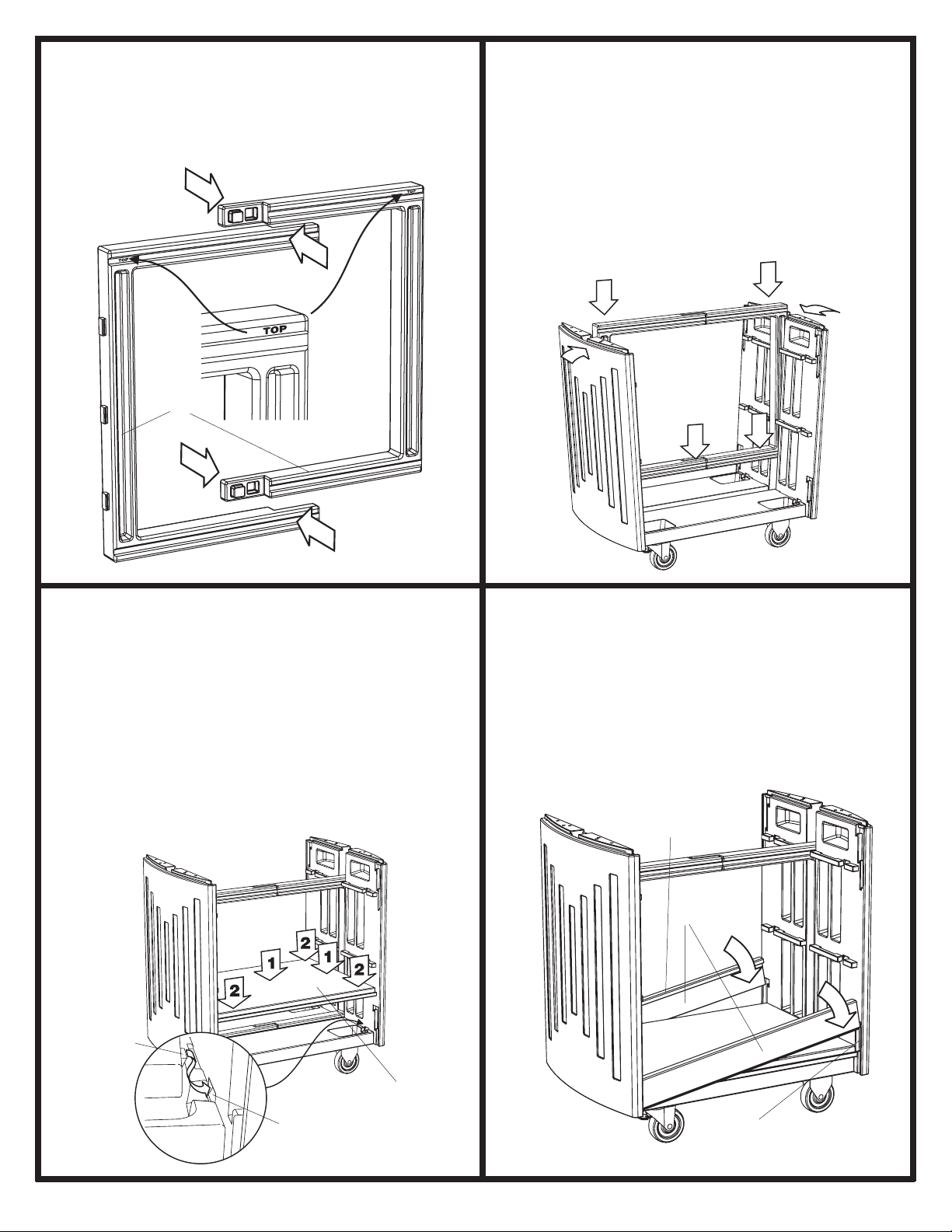
Congregue los dos U -apoyos I para formar un rectángulo.
Conecte las dos secciones juntos a los extremos solapando.
IMPORTANTE: encuentre la palabra “ TOP ” amoldó en las
esquinas superiores; esto identificará el extremo superior del
rectángulo para la próxima instrucción.
3
Ponga uno de los Estantes J entre los Paneles del Extremo,
cerca del extremo inferior del rectángulo de U -apoyo. Apriete el
Estante firmemente abajo, mientras guardándolo alinearon
encima del Panel de la Base. La pulgada final o para que
requerirá golpeando con la fuerza con un mazo de caucho (o un
martillo con un bloque de madera para proteger la superficie) a la
centro-línea del Estante para conectarlo encima de los U -apoyos.
Entonces golpea cada uno de las cuatro esquinas para que la
lengüeta en la esquina del Estante entre en el bolsillo en el Panel
del Extremo (vea la ilustración extra). LA INDIRECTA: desconecte
el extremo superior de los U -apoyos que para que los Paneles
del Extremo puedan extender ligeramente durante esta
instrucción, entonces re-conecte los U -apoyos.
5
Resbale el rectángulo congregado de los U -apoyos (con la
palabra “ TOP ” hacia arriba) abajo en los cauces en los Paneles
del Extremo. Hay ranuras de chaveta y espárragos de fijación,
similar a aquéllos en el Panel de la Base y Paneles del Extremo.
Empuje los Paneles del Extremo juntos como los acercamientos del
rectángulo el fondo del canal. Continúe resbalando el rectángulo
toda la manera abajo en el cauce en el Panel de la Base. Si los
espárragos de fijación laterales han conectado las ranuras
de chaveta propiamente, la cara interior del rectángulo de
U -apoyo estará nivelada con el Panel del Extremo.
4
Inserte un extremo de una de las Barras Laterales K en la
hendedura del fondo en uno de los Paneles del Extremo, al lado
del lado del Estante, con el labio de la Barra Lateral arriba y
enfrentando el Estante. Incline la Barra Lateral arriba a un ángulo
como mostrado, y encuadra su extremo superior con la ranura en
el otro Panel del Extremo. Inclínese la Barra Lateral abajo en la
posición, para que ambos extremos están dentro de sus ranuras.
Repita con otra Barra Lateral en el otro lado del Estante.
6
QQ
QQ
Q
QQ
QQ
Q
QQ
QQ
Q
LIPFACING
UP AND IN
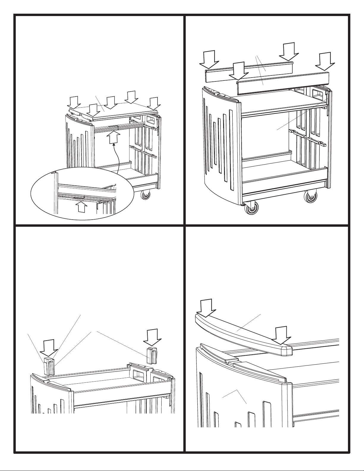
Ponga el segundo Estante J encima del extremo superior del
rectángulo de U -apoyo y entre los Paneles del Extremo, y
empuja abajo en la posición. Use el mazo de caucho (o martilla
con un bloque de madera) a cada esquina como antes de,
asegurar las lengüetas conectan dentro de los bolsillos.
IMPORTANTE: cuando las esquinas son seguras, aprieta abajo
en el centro superior del Estante, mientras usted golpea HACIA
ARRIBA en la juntura de U -apoyo hasta que chasquee en el
estante (vea la ilustración extra).
7QQ
QQ
Q
BARB LA LENGÜETA
=POCKET ELBOLSILLO
=
LABIO QUE ENFRENTA
ASCENDENTE E INTERIOR
=
SLOT LA RANURA
=
=UNIDADENSAMBLADA
Modele 5330
9
Resbale el permaneciendo dos Barras Laterales K abajo en las
ranuras superiores de los Tableros para el extremo.
8QQ
QQ
Q
Resbale un Tapón autoblocante L en el canal del centro de uno
de los Paneles del Extremo. Posicione la lengüeta que se sesga
para enfrentar el Panel del Extremo. Posicione la esquina que
tiene una muesca ascendente y enfrentando el interior de la
carreta. Empuje el Tapón autoblocante abajo entre el Tablero
del Extremo y el Estante, hasta la lengüeta chasquea en la
posición. Repita al otro Panel del Extremo.
Encuadre el tapón extremo M encima del Panel del Extremo sin
los Agujeros H . Apriete firmemente abajo hasta que haga clic
en la posición (puede ayudar hacer clic uno acaba primero,
entonces el otro; o cuidadosamente usa un mazo de caucho, o
un martillo con un bloque de madera, para golpearlo en la
posición).
10
QQ
QQ
Q
QQ
QQ
Q
11
13
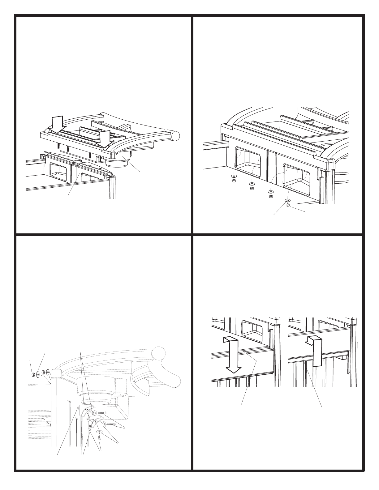
Ahora ate la bandeja / el asa N al otro Panel del Extremo con los
Agujeros G , alimentando los extremos del amoldar-en los pernos
a través de los agujeros superiores en el Panel del Extremo y
chasqueándolo entonces en la posición. LA NOTA: esto requerirá
cuidadoso use de un mazo de caucho o martillo con un bloque
de madera; no estropee o melle el plástico. También puede ser
útil tener una segunda persona para sostener la bandeja / el asa
en la posición mientras haciendo esto.
Ponga una Arandela Pequeña O terminado de los pernos de
la Bandeja / asa que se extiende en el hueco del Panel del
Extremo, como mostrado, y agrega una Tuerca Pequeña P ,
dedo-firme. Repita con tres Arandelas más Pequeñas y las
Tuercas Pequeñas en los pernos restantes. Ahora aprete todos
los pernos con un 10mm enchufe o la llave de boca abierta. NO
SE APRETE DEMASIADO.
12 QQ
QQ
Q
14
QQ
QQ
Q
QQ
QQ
Q
BARB LA LENGÜETA
=NOTCH LA MUESCA=
SLOT LA RANURA
=
KEYHOLE
SLOT STUD
LA RANURA
DE CHAVETA
=EL ESPÁRRAGO
DE FIJACIÓN
=
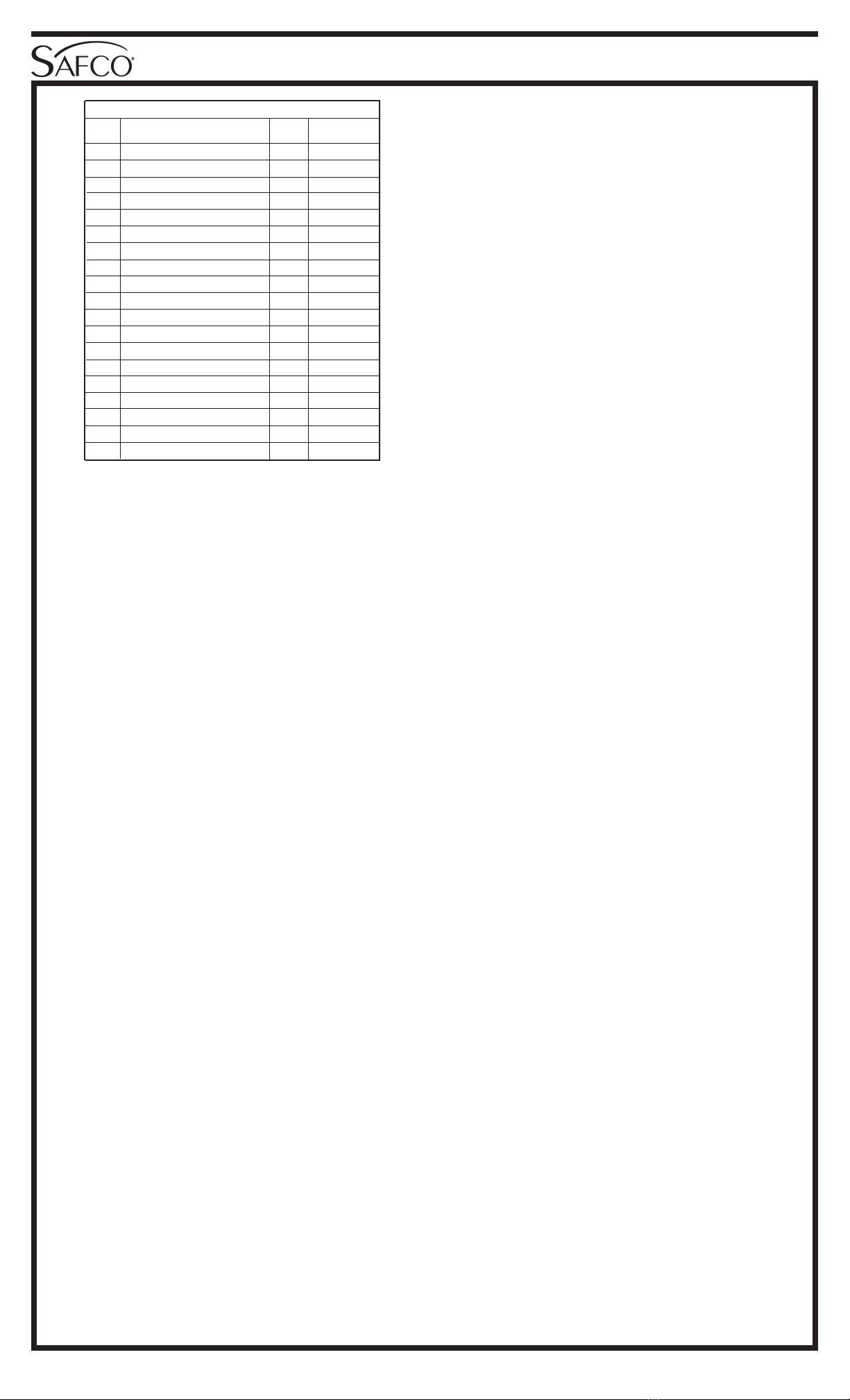
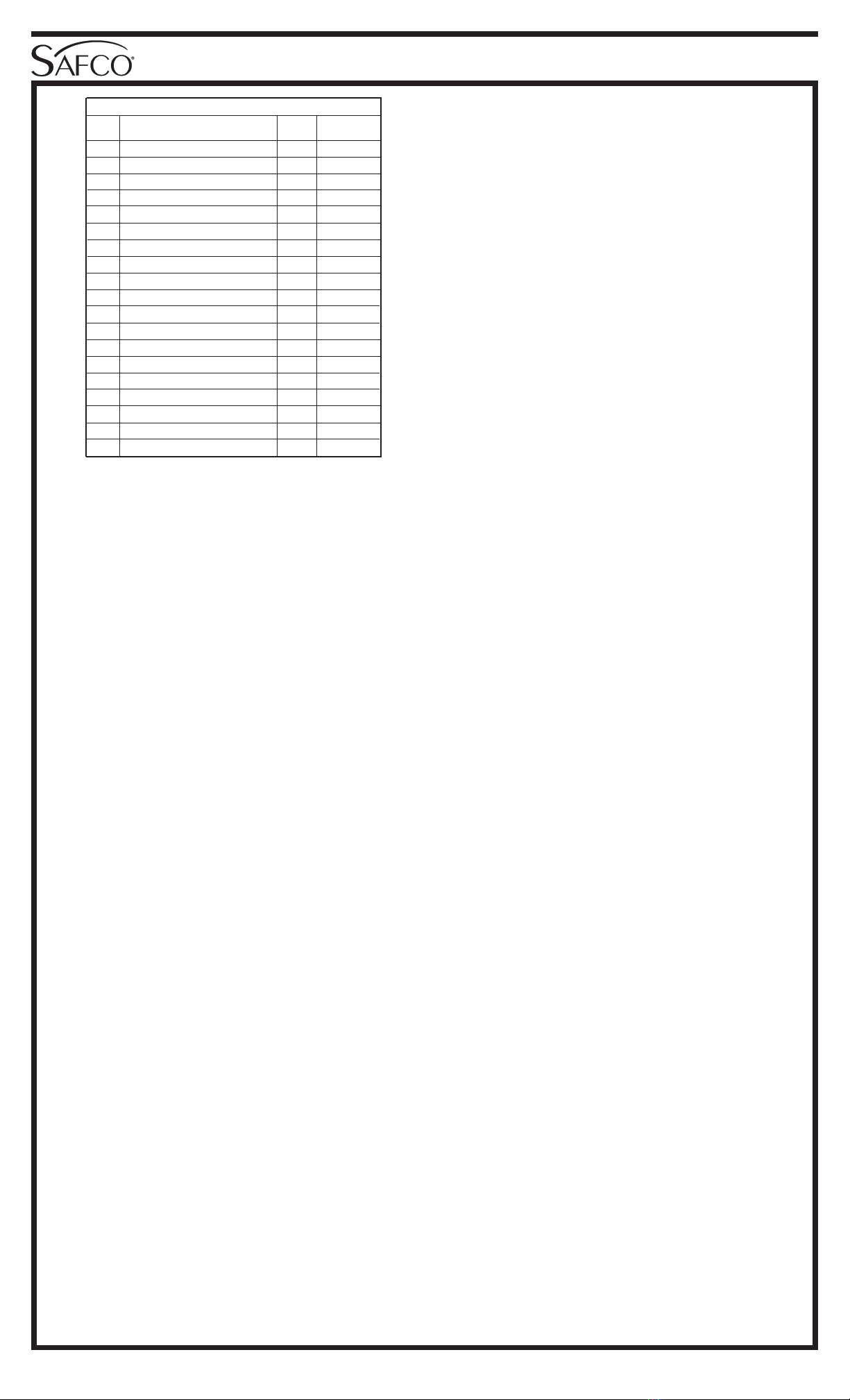
Panel Bajo 1 5330-07
Ruedas giratorias 2 5330-26
Perno espeso 16 5330-22
Arandela grande 16 5330-21
Tuerca grande 16 5330-24
Rueda fija 2 5330-25
Paneldelextremoconlosagujeros 1 5330-11
Paneldel extremo sin los agujeros 1 5330-01
U-apoyo 2 5330-02
Estante 2 5330-03
Barra lateral 4 5330-04
Tapón autoblocante 2 5330-09
Tapón extremo 1 5330-05
Bandeja / el asa 1 5330-06
Arandela pequeña 6 5330-31
Tuerca pequeña 6 5330-29
Perno delgado largo 2 5330-23
Anaquel 2 5330-28
Perno delgado corto 2 5330-27
Q
Q
Q
Q
Q
Q
Q
Q
Q
Q
Q
Q
Q
Q
Q
Q
Q
Q
Q
A
B
C
D
E
F
G
H
I
J
K
L
M
N
O
P
Q
R
S
NO. DE PIEZA
CÓDIGO
ALFABÉTICO
DESCRIPCIÓN CANTIDAD
LISTA DE PIEZAS
G tiene los agujeros aquí;
H no tiene ningún agujero
G has holes here;
H has no holes =
Resbale las ranuras de chaveta del Panel del Extremo con los
Agujeros G hacia los espárragos de fijación en el extremo del
Panel de la Base A que el asa se atará a, y empuja el Tablero
del Extremo al derecho para atarlo en la posición. Repita con el
Panel del Extremo sin los Agujeros H al extremo opuesto del
Panel de la Base.
QQ
QQ
Q
QQ
QQ
Q
QQ
QQ
Q
QQ
QQ
Q
H (Without Holes!) H (Sin los Agujeros!)
=
QQ
QQ
Q
Para mantener una superficie llana transportando los objetos
anchos, o para resbalar los objetos en y fuera del estante, eleve
las Barras Laterales ligeramente, tire afuera ligeramente, y deja
caer las Barras Laterales abajo hasta que ellos conecten con el
labio en el borde del Estante.
Forme una cesto por guardar los objetos en el Estante
invirtiendo este procedimiento hasta el borde del fondo de la
Barra Lateral se ata al labio del borde del Estante.
FLAT TOP SHELF:
Top lip of side rail
in lip of shelf edge
BOX TOP SHELF:
Bottom lip of side rail
in lip of shelf edge
EL ESTANTE LLANO: El labio
superior de barra del lado en el
labio de borde del estante
EL ESTANTE DEL CAJA-
ESTILO: El más bajo labio de
barra del lado en el labio de
borde del estante
=
=
Ate los dos Anaqueles R insertando dos Pernos Delgados
Largos Q a través de las Arandelas Pequeñas O , entonces a
través de los Anaqueles, y a través de los agujeros en el lado del
Tablero del Extremo Con los Agujeros G . Ponga otra Arandela
Pequeña O encima del extremo de los dos los Pernos Delgados
Largos, y ata flojamente con las Tuercas Pequeñas P . Luego
inserte un Perno Delgado Corto S a través de otra Arandela
Pequeña O y entonces HACIA ARRIBA a través del extremo
superior de un Anaquel y en la inserción fileteada en el lado del
fondo de la Bandeja / el asa. Aprétese los dos los pernos largos
y los pernos cortos, pero no SE APRETE DEMASIADO. Repita
con el Anaquel segundo, hacia el otro lado de la Bandeja / el asa.
QQ
QQ
QQQ
QQ
Q
QQ
QQ
Q
QQ
QQ
Q
QQ
QQ
Q
THREADED INSERT LA INSERCIÓN FILETEADA
=
QQ
QQ
QQQ
QQ
Q
QQ
QQ
Q
QQ
QQ
Q
QQ
QQ
Q
QQ
QQ
Q
HOLE AGUJERO
=
QQ
QQ
Q
Table of contents
Other Safco Outdoor Cart manuals
Popular Outdoor Cart manuals by other brands

Gorilla Carts
Gorilla Carts GORMP-12 manual

Oypla Leisure
Oypla Leisure 3847 user manual

Noble House Home Furnishings
Noble House Home Furnishings Barcart Assembly instructions

EINHELL
EINHELL SW 45/12 manual

Baileigh
Baileigh B-CART-TB Assembly and Parts Manual

John Lewis
John Lewis Riya 862 48203 instructions