Saft 777308-00 User manual

INDUSTRIAL BATTERY GROUP
Doc Ref:
ED2015-0544
User’s Manual
Lithium-ion Battery System (504V / 45 Ah)
Type of document:
User Manual
Created on: 04/12/2015
This document is Saft property. Any reproduction, diffusion or communication, even partial, are liable to prosecution without formal authorization.
Lithium-ion Stationary Battery System
P/N 777308-00
BTR-0504V-VL45E-NCA-009M
504V / 45Ah

2/45
DOCUMENT REVISION
Version
Date
Changes
1
04/12/2015
First issue 9 Synerion modules version based on the ED2014-
0210_UM_10 Syn48E battery_rev2

3/45
It is mandatory to read the user and the maintenance manuals prior to any use,
installation or maintenance of a Saft battery. All instructions must be carefully complied
with. In case any of the instructions contained in the user and the maintenance manuals
are not applied, Saft’s warranty on the battery is no longer applicable and Saft disclaim
any liability for any and all direct, indirect or consequential damages or losses resulting
thereof.
To highlight important points, the following symbols will be used:
Indicates a possibility of injury or serious equipment damage if instructions are not
followed
Indicates helpful information

4/45
SAFETY RULES
All the recommendations contained in this document must be applied and respected.
(1) Always use the batteries with restrictive access. Battery must remain
accessible only to trained service personnel.
(2) Install in a location that could be easily ventilated in case of misuse of
batteries such as described below.
(3) Misusing the batteries may cause them to overheat or ignite and cause
serious injuries. Make sure to follow the safety rules listed below:
Never short-circuit the battery terminals
Do not reverse the polarity
Do not overcharge or over-discharge
Respect the voltage range given in this manual.
Do not open the battery or modules
Do not disassemble the unit
Do not use the unit without its electronic management system
Do not subject to excessive mechanical stress
Do not expose the unit to water or condensation
Install the batteries in an area compatible with pollution level 2 according
to EN 60664-1 (typical of office or laboratory environments).
(4)Do not place the batteries on or near fires or other high-temperature locations
(> 70°C). Doing so may cause the batteries to overheat or ignite. Using the
batteries in this manner may also result in a loss of performance and a
shortened life expectancy.
(5)Immediately disconnect the batteries if, during operation, they emit an
unusual smell, feel hot, change shape, or appear abnormal in any other way.
Contact SAFT if any of these problems are observed.
(6)Prior to use the batteries, read carefully the Material Safety Data Sheet
supplied with the batteries.
(7)The battery systems must be used with the Synerion 48E modules described
in paragraph 2. Saft does not assure the behavior and the safety of the
battery system if another module is used.
(8)In case of contactor stuck closed (Alarm 18 rising), stop immediately the
battery charge or discharge.

5/45
TABLE OF CONTENTS
1. INTRODUCTION ..................................................................................................................7
1.1. Applicability.....................................................................................................................7
1.2. Acronyms........................................................................................................................7
1.3. Symbols..........................................................................................................................8
1.4. Referenced documents...................................................................................................8
2. UNPACKING AND INSPECTION.........................................................................................9
2.1. Battery characteristics...................................................................................................11
3. GENERAL DESCRIPTION OF THE BATTERY SYSTEM.................................................13
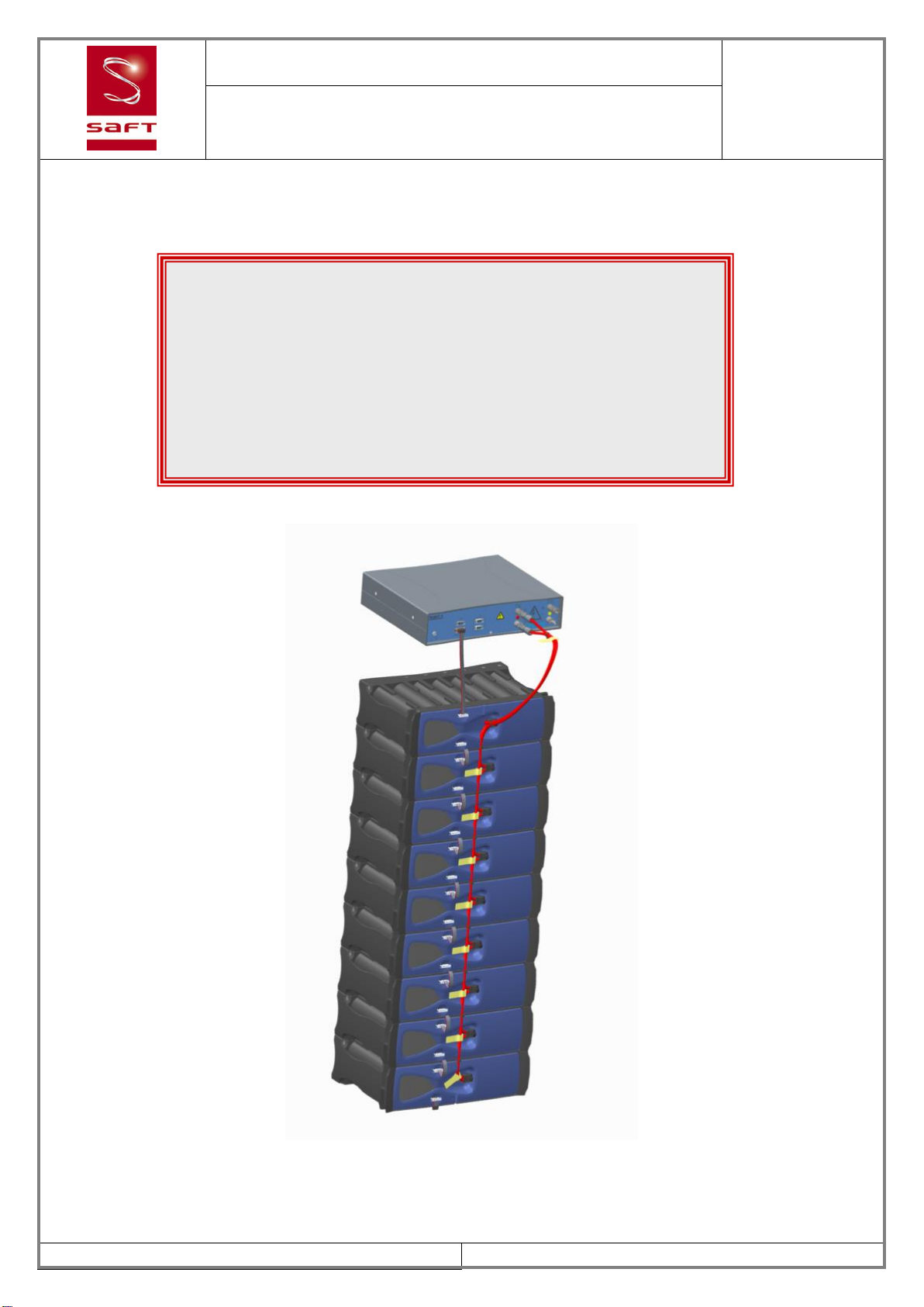
3.1. Synoptic........................................................................................................................13
3.2. Battery system..............................................................................................................14
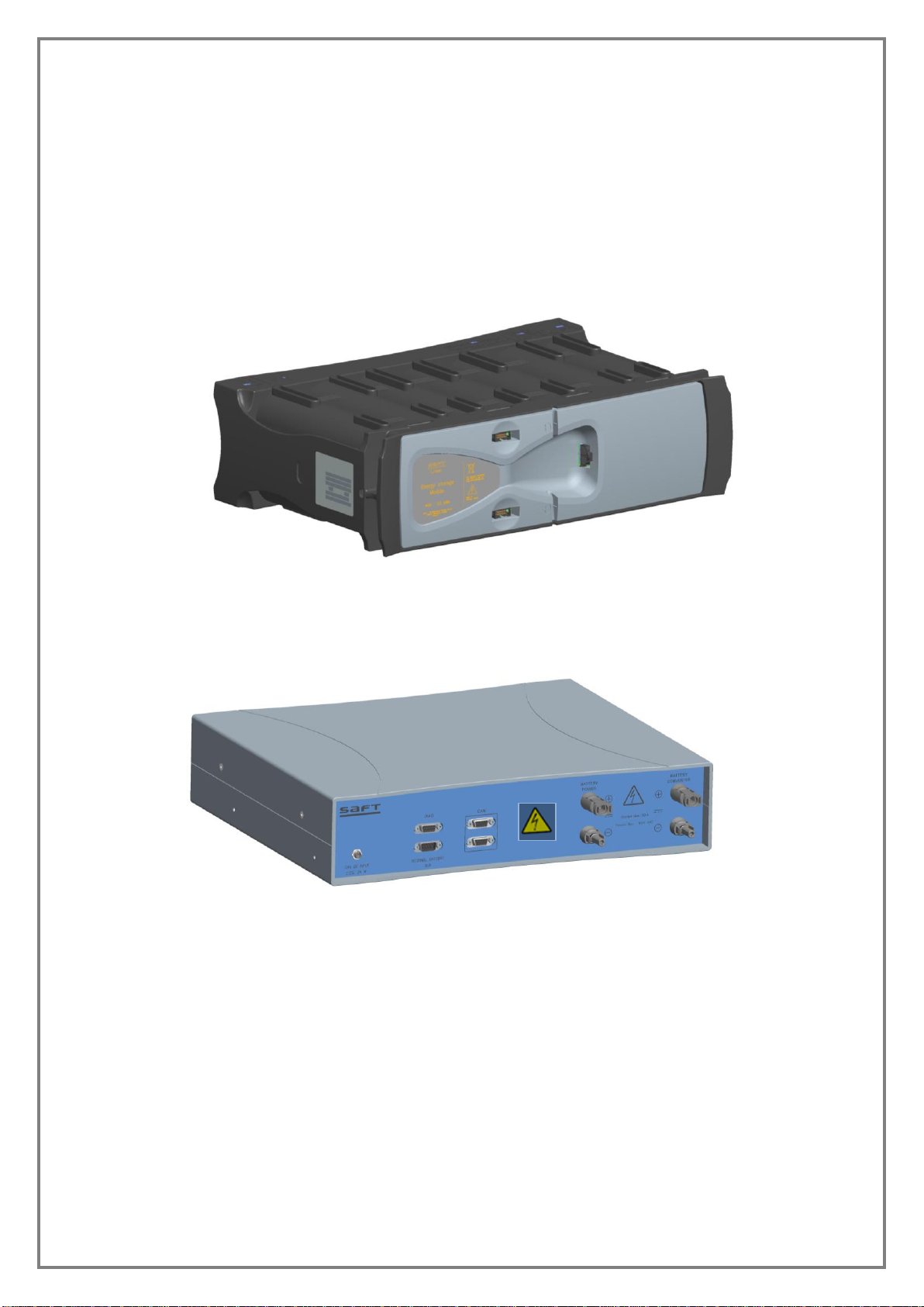
3.2.1. Li-ion Modules........................................................................................................14
3.2.2. BMM.......................................................................................................................14
3.3. HMI...............................................................................................................................15
3.4. Assembly installation ....................................................................................................16
3.5. Battery start-up.............................................................................................................16
3.6. Battery shutdown..........................................................................................................16
3.7. Gas exhaust..................................................................................................................16
3.8. Electrical interfaces.......................................................................................................17
3.8.1. Power connection...................................................................................................17
3.8.2. Electrical connection ..............................................................................................17
3.8.3. Communication connector......................................................................................19
3.8.4. Power supply connector.........................................................................................19
3.8.5. Earth connection ....................................................................................................19
3.8.6. Diagnostic interface................................................................................................20
4. BATTERY MANAGEMENT and Operating instructions.................................................21
4.1. General principle...........................................................................................................21
4.2. Safety functions ............................................................................................................21
4.2.1. Over charge protection...........................................................................................21
4.2.2. Over-discharge protection......................................................................................22
4.2.3. Over temperature protection...................................................................................22
4.2.4. Over current protection...........................................................................................22
4.3. Communication.............................................................................................................23
4.4. Operation during storage & maintenance .....................................................................23
4.5. Operational states.........................................................................................................24
4.6. Precharge .....................................................................................................................25
4.7. Battery charging............................................................................................................26
4.8. Charge profile description.............................................................................................26
4.9. Battery discharging.......................................................................................................28
4.10. Complete discharge & sleep mode............................................................................28
4.11. Alarms and warnings.................................................................................................28
4.12. Balancing...................................................................................................................29
4.13. Displayed information................................................................................................29
4.14. Communication with application................................................................................29
4.14.1. Data sent by BMM to EMS..................................................................................29
4.14.2. Data received by BMM from EMS.......................................................................30
4.15. SOH and EOL definitions...........................................................................................31
4.16. SOC definitions..........................................................................................................31
5. COMMISSIONING AFTER LONG STORAGE...................................................................31
6. HANDLING & STORAGE OF THE BATTERY MODULES................................................33
6.1. Handling........................................................................................................................33
6.2. Storage.........................................................................................................................33
6.2.1. Storage location .....................................................................................................33

6/45
6.2.2. Battery state of charge checking............................................................................33
6.2.3. Battery recharge in storage....................................................................................33
7. MAINTENANCE .................................................................................................................34
8. PACKAGING AND TRANSPORT......................................................................................35
8.1. Battery classification.....................................................................................................35
8.2. Training.........................................................................................................................35
8.3. Battery packing.............................................................................................................35
8.4. Charging state for transportation...................................................................................35
8.5. Document used for transportation.................................................................................35
9. DISPOSAL .........................................................................................................................36
10. APPENDIX I: Module Mechanical drawing...................................................................37
11. APPENDIX II: BMM Mechanical drawing......................................................................38
12. APPENDIX III: Power cable connection drawinG ........................................................39
13. APPENDIX IV: Termination connection drawing (771611)..........................................40
14. APPENDIX V: Inter modules connection drawing (771596)........................................41
15. APPENDIX VI: Module to BMM connection drawing (772872)....................................42
16. APPENDIX VII: Fault codes and alarm list of the battery system ..............................43
LIST OF FIGURES
Figure 1: Synerion 48E module....................................................................................................9
Figure 2: Battery Management System........................................................................................9
Figure 3: Power cable connection for 9 modules battery ...........................................................10
Figure 4: Communication ribbon cables.....................................................................................10
Figure 5: Battery synoptic ..........................................................................................................13
Figure 6: BMM HMI....................................................................................................................15
Figure 7: -polarity power connector............................................................................................17
Figure 8: +polarity power connector...........................................................................................17
Figure 9: Battery connection......................................................................................................18
Figure 10: CAN connector..........................................................................................................19
Figure 11: Power Supply connector...........................................................................................19
Figure 12: Diagnostic connector ................................................................................................20
Figure 13: Battery modes...........................................................................................................24
Figure 14: IMR & IMR_C versus SOC profile.............................................................................26
Figure 15: Battery charge profile................................................................................................27
Figure 16: VL45E normal rate charge profile (IMR & IMR_C vs T°C)........................................27

7/45
1. INTRODUCTION
This document contains the operating rules of the SAFT Lithium-Ion battery unit model for
Stationary Batteries 9 modules 504V max with limitation at 486V P/N 777308-00.
1.1. Applicability
This document describes functionalities and behaviour implemented in the BMM software
version 0.65 revH.
1.2.Acronyms
Acronym
Definition
Application
BMM
Equipment connected to the battery and consuming current from or feeding current to the battery
Battery Module Management
BMU
CAN
Battery Management Unit
Controlled Area Network
EDU
Electro-technical Device Unit
EMS
EOL
HMI
HVIL
Energy Management System
End Of Life
Human to Machine Interface
High Voltage Interlock Loop
I/O
Input / output signal
IMD
Maximum current allowed in discharge
IMR
Maximum current allowed in charge
Li-ion
Lithium Ion
MBMM
Master Battery Monitoring Module
N/A
N/U
PBIT
PoffBIT
P/N
Not Applicable
Not Used
Power on Built In self Test
Power off Built In self Test
Part Number
SMU
Safety Monitoring Unit
SOC
State Of Charge (Battery)
SOH
State Of Health (Battery)
TBC
To Be Confirmed

8/45
1.3.Symbols
Direct current
Caution
Caution, possibility of electric shocks
Li-ion recycling
1.4.Referenced documents
A reference document is used as a basis of work. Its strict application cannot be required.
: Document title
Emitter
Reference
Rev
[RD1] CAN OPEN dictionary for BMS
SAFT
SDU/SEL/DH 09-0974
L
[RD2] Diagnostic WinBMS Software User
Manual
SAFT
User_Manual_WinBM
S_11-1093
7
[RD3] Uninterruptible power systems
Electromagnetic compatibility (EMC)
requirements
-
CEI_62040_2
EN61000-6-2
EN61000-6-3
2006_06
2006_01
2007_03
[RD4] Electronic equipment for use in power
installations
-
NF_EN_50178
1999_10
[RD5] Transport of Lithium batteries
-
UN 3480
-

9/45
2. UNPACKING AND INSPECTION
Each module is packed separately. The BMM, connection kit and documentation are packed
together.
Check the packing material for any damages before accepting delivery from the carrier. If there
is any sign of damage, report it to the carrier and to SAFT and make a “certified letter with
acknowledgement” to the transporter.
For each battery system, ensure that the following parts are delivered:
9 Synerion 48E modules / 48V nominal / 45Ah: P/N 774842-00
Figure 1: Synerion 48E module
1 BMM: P/N 776354-01
Figure 2: Battery Management System

10/45
Connection Kit:
oPower cable to connect modules and BMM (see drawing on Appendix III):
Figure 3: Power cable connection for 9 modules battery
oCommunication ribbon cables kit to connect modules and BMM:
Figure 4: Communication ribbon cables
1 CDROM or USB key with SAFT diagnostic software (DiagWinBMS) and its
User Manual
It is advised to save the original packaging for reuse in case of later shipment.
Termination connection: P/N 771611
- 1 per battery
(see drawing on Appendix IV)
Inter-module connection: P/N 771596
- 8 for 532V battery
(see drawing on Appendix V)
Module to BMM
connection: P/N 772872
- 1 per battery
(see drawing on Appendix VI)

11/45
2.1.Battery characteristics
The table below gives the main characteristics of the battery and BMM:
Battery electrical
characteristics
9 modules
Unit
Nominal voltage
432
V
Maximum voltage
486
V
Minimum voltage
378
V
Minimum capacity (C/3, 25°C)
31.5
Ah
Maximum continuous charge
current allowed (normal charge)
-
@ +35°C
29
A
@ +20°C
20
A
@ 0°C
11
A
@ -20°C
5
A
Maximum discharge current
- Continuous
50
A
- 30s pulse
60
A
Insulation:
Compliant with EN 50178:
-
- pollution degree
- Overvoltage category I, pollution d°2
-
- insulation resistor @1000Vdc
- > 1
MOhm
- dielectric
- 1350Veff_AC / 50Hz
Vrms
BMM electrical characteristics
Power supply characteristics
TBTS compliant with CEI_60950-1
- touch current
< 0.25
mA
- voltage
24 +/-5
Vdc
- maximum current
1
A
- maximum power
24
W
- ripple
< 100
mV
- inrush current
700
mA
Insulation:
Compliant with EN 50178:
-
- pollution degree
Overvoltage category I, pollution d°2
-
- insulation resistor @1000Vdc
> 1
MOhm
- dielectric
1350Veff_AC / 50Hz
Vrms
Maximum current
- Continuous
50
A
- 30s pulse
(circuit opened after 30s)
60
A
Mechanical characteristics
Unit battery module Width
445
mm
Unit battery module Depth
293
mm
Unit battery module Height
131
mm
Unit battery module Weight
18.5
kg
BMM Width
420
mm
BMM Depth
372
mm
BMM Height
92
mm
BMM Weight
4.01
kg
Protection Index
IP 20
-
General characteristics
Operating battery temperature
range
(derating between 50°C and
-20 to +60
°C

12/45
60°C)
Storage battery temperature
range
-20 to +75
°C
Recommended storage battery
temperature range (to preserve
lifetime)
< +40
°C
Recommended storage BMM
temperature range (to preserve
lifetime)
-20 to +65
°C
Maximum altitude
2000
m
Environmental conditions
Interior without air conditioning, not condensing:
B type following EN50178-1:1997
-
- Environment temperature
+5 to +40
°C
- Environment humidity
5 to 85
%
EMC
Following EN 62040-2:
C3 for immunity, C1 for emissions
-
- Electrostatic discharge
+/-4kV contact - +/-8kV air
-
- Fast transient-Burst
2kV - 5kHz - Capacitive clamp
-
- Magnetic field
30A/m - 50Hz
-
- Radiated immunity
10V/m from 80 to 1000MHz - 80% AM (1kHz)
-
- Radiated emission
30 dBµV/m from 30 to 230MHz at 10m
37 dBµV/m from 230 to 1000MHz at 10m
-
Vibration
IEC 62093: 2g from 10hz to 150Hz
-
Shocks
IEC 62093: 15g, 11ms
-
Transport of Lithium batteries
UN 3480
-

13/45
3. GENERAL DESCRIPTION OF THE BATTERY SYSTEM
3.1.Synoptic
Figure 5: Battery synoptic
Module: 14 cells in
series (54V max)
Module: 14 cells in
series (54V max)
Module: 14 cells in
series (54V max)
Module: 14 cells in
series (54V max)
Module: 14 cells in
series (54V max)
Power supply: 24V
Module: 14 cells in
series (54V max)
BMM
RS485
Diagnostic
bus
9 modules in series
+BATT
-BATT
Module supply : 5V
Module: 14 cells in
series (54V max)
Module: 14 cells in
series (54V max)
Module: 14 cells in
series (54V max)
CAN Open
Customer
bus

14/45
3.2.Battery system
Li-ion battery is made of:
An assembly of Li-ion modules connected in series.
A Battery Management Module (BMM) which is the interface between battery and
customer application.
An external power supply (24V) is needed to supply the BMM (see §2.1 for characteristics).
3.2.1. Li-ion Modules
Li-ion modules contain 14 cells connected in series.
A 200A fuse protects the module against short-circuit (fuse not replaceable).
Each module contains an electronic board (named SMU) which monitors and sends the
following information to the BMM:
1 temperature measurement
14 cell voltages measurement
1 emergency signal (digital line) driven by redundant hardware channel. This signal is
active in case of:
Cell over charge
Cell over discharge
Module over temperature
Module switched OFF
The electronic board manages also the cells balancing and the data timestamp.
3.2.2. BMM
The Battery Management Module (BMM) optimizes the battery performances and protects the
battery against extreme situations (over charge, over discharge, over temperature). The BMM
monitors all modules and communicates with the customer application to manage battery cycles
(charge and discharge).
The BMM functions are:
Management of SMU boards (calculation of the data from the modules)
Measurement of the battery current
Battery over current protection (by 50A fuse)
Protection of the battery unit
Communication with the EMS via CAN Open bus
Diagnostic functions using a RS485 bus

15/45
3.3.HMI
The figure below shows the BMM interface:
Connection from modules Connection to converter
Red point side
Yellow point side
Figure 6: BMM HMI
CAN
Communication
to EMS
RS485
Diagnostic
24Vdc Power
supply
CAN Communication
to SMU
Battery
converter
connection
(+polarity)
Battery
converter
connection
(-polarity)
Battery
connection
(-polarity)
Battery
connection
(+polarity)

16/45
Installation
The cabinet in which the battery will be installed must be in closed electrical enclosure
according to chapter 5.2.7 of EN50178-1:1999 standard.
If the product is brought to the installation location from a cold environment, condensation may
form and this may lead to damage the electronic equipment. Before commissioning, the product
must be dry. Wait 2 hours after transportation before installing the product.
3.4.Assembly installation
The modules must be stacked horizontally. They must be protect against external aggression
(shock, piercing, short-circuit, water, falling of objects, pollution dust,…).
If the battery is not installed inside a closed cabinet, no flammable material must be stored near
the battery (2 meters radius).
3.5.Battery start-up
The start-up is done by supplying the BMM with 24VDC. The BMM immediately proceeds to its
self-test by testing its internal functions.
During self-test, the battery will be connected. Beware of high voltage.
The battery communicates by CAN-Open protocol. At start-up, the CAN-Open node is in Pre-
operational State: the BMM waits for a Start_Remote_Node frame (with CAN-Open NMT
service) to go to Operational State. After that, the BMM is operational and sends continuously
messages on CAN Open bus.
Then the EMS must authorize the contactor closing by sending a command by CAN (CAN
Open Object 2055 on RPDO2): at this stage, EMS can use the battery properly.
3.6.Battery shutdown
To shut-down the battery, disconnect the 24VDC supply voltage (battery contactor opens within
5s and the connections has no voltage anymore). Before opening, be sure that there is no
current to prevent damage to the contactor.
3.7.Gas exhaust
In case of abusive situations, electrochemical cells may open and dissipate hot gases under
pressure. Battery must be located in a room, where people are not staying permanently (with
ventilation if the room volume is less than 25m3).

17/45
3.8.Electrical interfaces
3.8.1. Power connection
Power connectors used for Battery and Inverter (-polarity) connections: PV-ADBP4/6 from Multi-
contact.
Figure 7: -polarity power connector
Power connectors used for Battery and Inverter (+polarity) connections: PV-ADSP4/6 from
Multi-contact.
Figure 8: +polarity power connector
3.8.2. Electrical connection
The modules must be connected only after their installation: connect them together and
to the BMM, as shown in the drawing below, with the red power cable delivered with module.
Then, connect the modules together and to the BMM with the three kinds of cables delivered
with the battery (see §2):
Inter-module ribbon cables
Module to BMM ribbon cable
Termination connector ribbon cable
Then, connect inverter to the BMM “Battery converter” connectors.
Never start the battery system without connecting battery cables and inverter cables to
the BMM.
Never connect a charger with a voltage below the battery voltage.

18/45
Note: the following picture represents the battery connection (only 5 on 9 modules are
represented).
Figure 9: Battery connection
Don’t short-circuit the module terminals.
The battery circuit must be kept insulated from the ground. Battery polarities must NOT
be connected to any part of the chassis or other conductive part.
Never disconnect power connections under load.
Inter-module
power connection
CAN termination
connector on the
last module
Inter-module
communication
connection
Module to BMM
communication
connection
Module to BMM
power connection

19/45
3.8.3. Communication connector
Two Sub-D9 female connectors are used for CAN Open communication bus: one or the other
connector could be used (both connectors are pin to pin connected).
We recommend using a cable less than 3 meters length for CAN communication with BMM
(cable shielded with 120Ω adaptation).
These connectors are insulated from High voltage by a protective separation.
Figure 10: CAN connector
Nota: Spare_1 and Spare_2 pins are used for power supply gateway. The maximum current
must be 1A.
3.8.4. Power supply connector
A three contacts male connector (ref. 1440070 from Phoenix Contact) is used to supply the
BMM. See §2.1 for BMM power supply characteristics.
Compatible with ref. 1681172 or 1506888 from Phoenix Contact.
This connector is insulated from High voltage by a protective separation.
Figure 11: Power Supply connector
The 24V external power supply must be protected against overcurrent higher than 2A.
3.8.5. Earth connection
The 24V power supply of the BMM circuit must be earthed.
1 : GND (0V)
3 : 24Vdc
4 : N/U
1
3
4
1 : Spare_1
2 : CAN_L
3 : GND (0V)
4 : Saft reserved (don’t connect)
5 : Spare_2
6 : Saft reserved (don’t connect)
7 : CAN_H
8 : Saft reserved (don’t connect)
9 : Saft reserved (don’t connect)

20/45
3.8.6. Diagnostic interface
One Sub-D9 female connectors is used for RS485 diagnostic bus.
This connector is insulated from High voltage by a protective separation.
Figure 12: Diagnostic connector
1 : RS-485_A (+)
2 : RS-485_B (-)
3 : CAN_L
4 : CAN_H
5 : GND (0V)
6 : 24Vdc (Power Supply)
7 : N/U
8 : CAN_L_SMU (Saft only)
9 : CAN_H_SMU (Saft only)
Table of contents
Other Saft Batteries Pack manuals