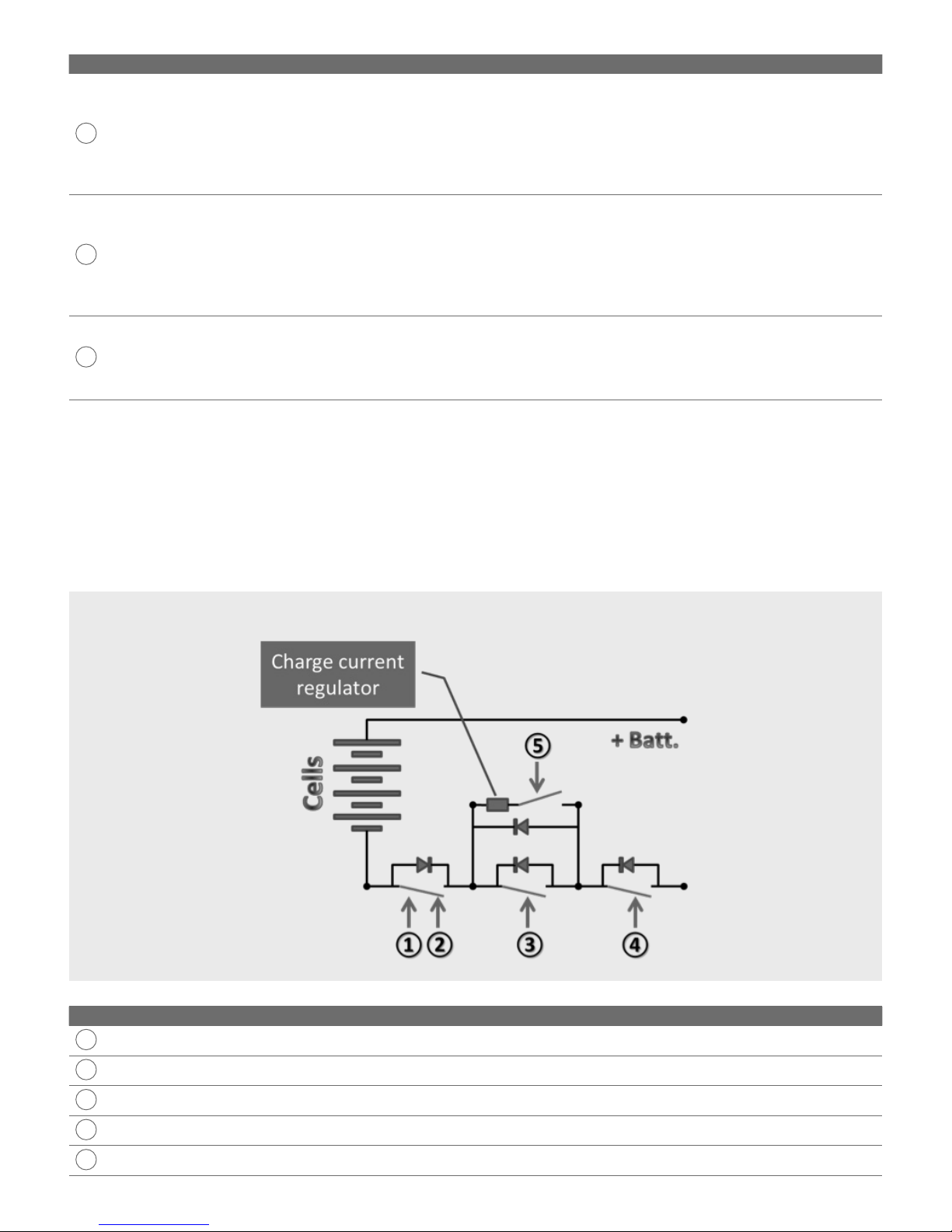
Saft evolion User manual

Evolion®
Li-ion battery
Technical manual

3
1. Introduction 4
2. Electrochemical principles 4
3. Evolion construction 5
Contents
3.1 Module characteristics
3.2 Interface features 7
3.3 Main functional features 8
3.4 Front cover features 8
4.1 Application summary
4.2 The electronic switch (mosfets) 10
4.3 Operating modes 11
4.4 Internal electronic load 11
4.5 Internal heater 12
4.6 Cell balancing 12
4.7 System level and cell level current interrupt devices 12
4.8 Safety limits during operation 13
4.9 Module self test during startup 14
4. Evolion operation 9
5. Cell and module voltages 15
6. Internal resistance 16
7. Discharging 16
5.1 Normal operating voltage limits
5.2 Cell self discharge 15
5.3 Open Circuit Voltage (OCV) as a function of State of Charge (SoC) 15
7.1 Discharge performance factors
7.2 Maximum discharge current 18
7.3 Low voltage disconnect 18
8. Charging 19
8.1 Maximum re-charge current (IMR)
8.2 Power system set points 21
8.3 Re-charge time 21
8.4 Heat sink dissipation in charge regulated mode 22
9. Gassing and ventilation 22
9.1 Cell venting in operation
9.2 The probability of an internal short 23
9.3 Released gas characteristics 23
10. Service life 23
11. Communication 26
12. Black box 26
13. Special operations 27
13.1 Massive paralleling
13.2 Thermal characteristics in cycling 28
13.3 Adding modules to existing bus 29
14. Abusive operations 30
15. Battery sizing 30
15.1 Autonomy sizing
Appendix A: Part number reference 32
Appendix B: Glossary 32
Appendix C: Performance rate tables 33
Appendix D: Derating factors for sizing 33
Appendix E: Alarms and troubleshooting 36
Appendix F: BMST versions 42

4
The Saft Evolion® is suited for many different applications and environments and its compact size and high energy density allow it to
deliver the highest performance from a smallest volume and weight. The Evolion offers a unique combination of high float charging life
and high cycling performance in the same technology.
The Evolion is a Li-ion battery system. The battery system or module includes two main parts, a Li-ion cell pack and electronics. Both
combine together to make a smart battery module. The module operates in a single package and as a standalone 48 Vdc unit. It can
communicate to/from the application (dry contact signal and RS485 transmission bus) and can report its status using the user friendly
Saft DiagWinBMS communication kit.
This manual gives the technical features, operating characteristics and operating limits of the Saft Evolion module when it is applied in
standby applications and frequent cycling applications.
1. Introduction
2. Electrochemical principles
The electrochemical pack of Li-ion cells is the heart of the module. The cells use the NCA (Nickel Cobalt Aluminum) electrochemistry.
NCA refers to the active material mixture of the positive electrode. The mixture includes metal oxides in a composition of LiNiXCoyAlzO2,
hence, a Nickel Cobalt Aluminum mixture or NCA.
The positive electrode stores lithium ions through intercalation during discharge. The negative electrode is composed of graphite
active material. It stores lithium ion through intercalation during charge. Refer to Figure 1.
Figure 1. The reaction mechanism of the lithium-ion cell.

5
The Evolion is a single 48 V module. The main components include a 14 cell pack of VL80E and two main electronic printed circuit
boards. A
Battery Management System Telecom (BMST)
is built into each module. With its microprocessor combined with the BMST
software (or firmware), the BMST optimizes the performance and protects the Evolion against situations like over charge, over and
under discharge, over and under temperature or over current. No external BMS is used. Each Evolion can be installed and operated
independently regardless of the number connected on the same power bus.
The BMST also allows communication via RS485 bus with the Saft Evolion Toolbox supervision software, for diagnostics or application
controller and its software, for feedback control. It can also integrate to the application alarm panel using a dry contact signal.
3. Evolion construction
A spirally wound electrode coil is used. The electrodes are made by depositing the active materials, mixed with a binder and
conductive agents, on a current collector. A metallic copper is used for the negative current collector and a metallic aluminum is
used for the positive current collector. A non-conductive separator material is interleaved in the coil to prevent short-circuiting of the
positive and negative and allow the electrolyte to conduct the lithium ions.
The electrolyte consists of a proprietary mixture of alkyl carbonates and lithium salt. A vinylene carbonate additive is used for negative
electrode SEI formation (Solid-Electrolyte Interface). The electrolyte is non-aqueous. The electrolyte conducts lithium ions from the
positive to the negative during charge and discharge.
The Li-ion electrochemistry accepts charge current with approximately 100 % coulombic efficiency over all temperature ranges. Unlike
aqueous battery technologies (Ni-Cd and Lead acid), the Li-ion electrochemistry does not use side reactions, like water electrolysis,
even when fully charged. Overcharging will not occur with Li-ion technology. Once the cell is fully charged, an insignificant amount of
charge current will be accepted by the cells. The Saft NCA lithium ion cell is sealed and does not produce or exhaust any gases during
normal operation.
The reaction mechanism of lithium-ion batteries is represented by Figure 1. The positive and negative materials facilitate intercalation
of lithium ions. The net effect of the charge and discharge reaction is the movement of lithium ions back and forth between the
electrodes. The corresponding flow of electrons in the external circuit is proportional to the ion flow between the electrodes. There is
no lithium metal formed in the NCA Li-ion electrochemistry used in the Evolion and therefore there are no hazards associated to that.
The Li-ion cell pack operates in a system combined with electronics (see section Evolion construction). The system is designed with
redundant safety functions to make sure the cells never exceed a preset operating level. One of the main safety factors is the cell
temperature limits. The Evolion operates normally and safely in the temperature range from - 40°C to +75°C (- 40°F to + 167°F).
Important note: Chemical instability begins at above + 80°C (+ 176°F).

6
3.1 Module characteristics
Parameter Value
Typical capacity @ C/8 A and 25ºC 77 Ah
Rated capacity @ C/8 A and 25ºC 74 Ah
Rated capacity @ C/5 A and 25ºC 73 Ah
Rated capacity @ C/24 A and 25ºC 79 Ah
Width 216 mm (8.50 inches) equivalent to 5 RU
Depth 404 mm (15.91 inches)
Height 260 mm (10.24 inches) equivalent to 6 RU
Weight 30 kg (66 lbs)
Case Material Polycarbonate, UL94 V0 compliant
Protection index (IP)
IP20
It is also waterproof when immersed in water up to 6 inches
(15.2 cm) from the bottom when mounted right side up.
Nominal voltage 48 Vdc
Maximum voltage 56 Vdc
Minimum voltage 42 Vdc (internal Low Voltage Disconnect or LVD)
Maximum charge current @ 20ºC (Note 1) 32 Amps
Maximum discharge current @ 20ºC (Note 2) 44 Amps
Operating temperature range -40ºC / +75ºC (- 40ºF / +167ºF)
Storage temperature range -40ºC / +75ºC (- 40ºF / +167ºF)
Maximum relative humidity 95% (non condensing)
Maximum operating altitude 3000 meters (9843 feet)
Insulation resistance @ 500 Vac 1 Mohm
Dielectric resistance 500 Vrms
BMST version See Appendix F
Note 1: The maximum charge current is a function of the measured battery temperature and represents the limit where the regulated charge mode will be
activated. See section Charging for more details. The values are given for BMST software version 0.57 and later.
Note 2: The maximum discharge current is a function of the measured battery temperature and represents the limit where the battery will not discharge if
exceeded. See section Discharging for more details. The values are given for BMST software version 0.57 and later.

7
3.2 Interface features
#Interface feature Description
1Power terminals
The terminal cover caps are IP2X compliant. The connecting hardware is M6 and the maximum
torque is 6 Nm (53 in lbs). The maximum cable size that can be routed in the cable channels is a
16mm2section or gauge 6 AWG. 36 Vdc minimum is needed to automatically wake up the module.
2RJ45 connections
The RJ45 protection caps are IP3X compliant. Both 8 pin connectors are connected in parallel and
can be used interchangeably to access the signals. All the pins are 1500 Vdc isolated.
Pin Type Description
1RS485+ transmission bus Modbus communication protocol
2RS485- transmission bus
3Ground (isolated from power terminals)
4Wake up (referenced to Ground) 12 Vdc signal
5Not used
6Not used
7Dry contactor (not polarized) 100 mA/60 Vdc max., CLOSED = alarm or power
down, OPEN = no alarm
8Dry contactor (not polarized)
3LED’s
Four LED’s are used and are numbered 1 through 4. During operation they give information about
the module operating mode, i.e., charge, float charge or discharge and its alarm state. They provide
SOC information when the SOC button is pushed.
4ON/OFF button
This button toggles the Evolion module OFF or ON. When OFF no LED’s are lit and the unit remains
in sleep mode.
ON = press 2 seconds
OFF = press 4 seconds
Important: High discharge current, due pre-charging a capacitance on the rectifier output circuit may
open, the replaceable fuse. As a general rule, never use the ON/OFF button to turn the Evolion ON
after the power terminals are connected to the application.
5SOC button This button gives the module SOC indicated on the 4 LED’s.
6Heat sink Dissipates the extra power when the module has regulated charge mode active. The metal surface
offers a grounding connection point that uses an M3 screw.
7Handles Hand lifting points.
8Label Manufactured information.
9Vent ports Allows gas escape in the abnormal event of cell venting.

8
3.3 Main functional features
#Interface feature Description
1Cell pack
The series connected cells are configured in a high energy dense cell pack. Each cell is equipped with an
internal current interrupt device. In case the maximum internal pressure or a maximum current level
is exceeded, this device opens the current flow in the series pack. Additionally, each cell is designed to
open and allow abnormally high pressure to vent. This controlled venting minimizes the risk of a flare up
event. Further, each cell is spaced and externally sleeved with an optimal distance in order to prevent
thermal propagation from one cell to another, in the unlikely event of a cell flare up.
2BMST busbar board
The cell pack is connected with a BMST busbar board. The BMST busbar board is located just under
the top cover and it provides several functions. It is a power supply, a microcontroller, it monitors
cells’ voltage, it measures temperature, it balances cell voltages, it provides redundant monitoring,
it measures network & module voltage, it generates alarms, it provides external communication, it
provides the front panel HMI, heats the cells and measures current.
3BMST power board
The BMST busbar board interconnects with the BMST power board. It is located just under the front
face and it provides several functions. It is the charge control, the discharge control, includes a mosfet
test and provides the overcurrent protection. It mounts the module power terminals, BMST reset button
and replaceable fuse. The front cover is removable to access the reset button and the replaceable fuse.
Refer to the figure and table below.
#Front cover feature Description
1Power terminals
Power connection to the bus. Use only approved power cables provided by Saft or equivalent (with
continuous current carrying capability of 63 Amps). The maximum torque is 6 N·m (53 in·lbs).
Important: If the power terminals are reverse connected to the rectifier output the battery will not start.
If the ON/OFF button is forced to start the Evolion ON, then alarm 27 and 47 will activate and the Evolion
will be in safe mode.
2BMST reset button
Push button micro switch is recessed in hole and it is
used to reset the BMST microprocessor in case of a
software trap or an emergency alarm.
3Replaceable fuse
Power fuse rated at “60 A”. Use only approved fuse provided by Saft or equivalent (supplier: Ferraz
Shawmut, type: 2.5 URGS 17/60). See Figure 4 for fuse limit characteristics. Protects the Evolion
against external short circuit.
3.4 Front cover features
steady Emergency alarm
steady Software trap

9
The Evolion is designed for 48 Vdc nominal power systems. The applications can be grid connected or off grid and the Evolion can
remain on float or cycled frequently over its useful life.
4.1 Application summary
The Evolion is a standalone battery system.
The Evolion is designed for installation in indoor or outdoor sites. The temperature can be controlled or uncontrolled. The enclosure,
compartment or area where the Evolion is placed should have a minimum protection index of IP55.
The Evolion discharges with rates equal to 2 hours of autonomy and higher runtimes. It re-charges fully in 3 to 24 hours (from a full
discharge). Typical applications include standby power for remote terminals, BTS, customer premises, underground vaults, huts and
DPCO for good power grid or poor power grid regions and in hybrid power and solar applications for off grid sites.
The Evolion is connected to the application with power cables and with an optional communication cable. Units can be connected in
parallel to increase the battery bank capacity and power but it is never allowed to build a series to increase the system voltage. The
Evolion can only operate on a 48V bus.
The dimensions are optimized to fit with good volumetric efficiency in a standard 19” (upright orientation) and a standard 23”
equipment rack (sideways orientation). The module interface features are front accessed which allows it to adapt well in confined
roadside cabinet compartments. When the Evolion is integrated in the application, the following functions are built into each module.
4. Evolion operation
Figure 2.
Schematic view of Evolion
connected to application.
The following BMST software versions are compatible to connect and operate in parallel.
BMST software version Parallel connect and operate
0.55 & 0.56 OK
0.57 & 0.58 OK OK
0.59 & 1.00 OK
Upgrading all operating Evolions to the latest BMST software version is always recommended. Contact your local Saft representative
to upgrade procedure details.
See the Figure 2 below for a schematic view of Evolion installed in the application. For more details about the “Switch”, see chapter
The electronic switch (mosfets).
• Compatibility with typical telecom rectifiers
(60 V maximum rated output)
• Charge current regulation
• Low voltage discharge cut-off (42 V)
• Safety disconnecting through system level micro-controller
and mosfet contactor
• Safety disconnecting through system level redundant
hardware safety chain or fuses
• Safety disconnecting through cell level current interrupt
devices
• LED’s, dry contact signal and RS485 communication bus
• Operation status through LED’s and RS485 bus
• State of charge and state of health status through LED’s and
RS485 bus
• Automated internal heater operation

10
Figure 3. Schematic view of the electronic switch (mosfets) in the Evolion.
#Application parameter Description
1Load limits
Each module can provide and accept up to 44 A of discharge/charge current. To avoid damaging the
BMST power board, the maximum total system discharge load should be below 130 Amps. If the total
system discharge load exceeds 130 Amps, regardless of the number of parallel Evolion modules, it is
necessary to implement an external protection device like a Saft specified breaker (per Evolion or pair
of Evolions) and/or an electronically controlled contactor(s) piloted by a signal by measured Evolion
parameters (via RS485 or external measurement). See details in the chapter Massive paralleling.
2Re-charge limits
The Evolion uses an automatically actuated charge regulated mode, so normally sized rectifier outputs
are compatible with Evolion operation. If a minimum re-charge time is needed, it is necessary to control
the charge output to avoid charge regulated mode and possible damage to the BMST power board. The
rated output of the charger should be 60 V maximum. A higher rated output allow a high current or high
voltage transients, for a short time, even if the set point is lower than 60 V. In charge regulated mode,
the typical re-charge time can be up to 24 hours. See details in the chapter Massive paralleling.
3Communication/
alarms
The transmission protocol is RS485. The communication protocol is Modbus. Application controllers
can communicate with the Evolion or parallel connected Evolions to receive information or command the
Evolion’s state. A dry contact signal is also actuated (normally closed) when customer specified alarms
are exceeded or the module power is OFF.
#Switch Description
1Discharge Mosfet driver for discharge acted on by BMST microcontroller
2Redundant discharge Mosfet driver for discharge with delay time acted on by the redundant hardware safety chain
3Fast charge Mosfet driver for charge acted on by the BMST microcontroller
4Redundant charge Mosfet driver for charge with time delay acted on by the redundant hardware safety chain
5Slow charge Mosfet driver for regulated charge acted on by the BMST microcontroller
4.2 The electronic switch (mosfets)
The Evolion operates with 6 modes. The modes are invoked by controlling the state of an
electronic switch
circuit (combined with
diodes). The switch circuit is located on the BMST power board. The electronic switches are acted on by the BMST microcontroller
or the redundant hardware safety chain. The electronic switch state depends on the measured value of the single module’s state
variables, i.e., voltage, temperature and current. See the Figure 3 below for a schematic overview of the electronic switch (mosfets)
located on the BMST power board.

11
4.3 Operating modes
In all modes except sleep mode, the terminal voltage is present, the RS485 communication is active, the LED’s operate and the dry
contactor operates. Each Evolion controls its own switch state, independent of other parallel connected modules, without the need of
an external master battery management module.
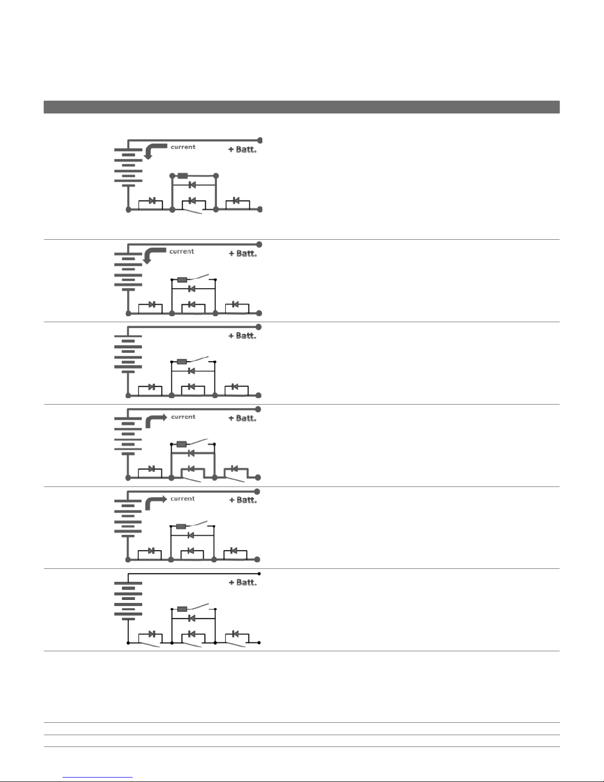
Mode Schematic Description
Regulated
charge
Charge current is accepted anytime the network voltage is higher than
the Evolion terminal voltage. Current is accepted through the current
regulation device. If the charge current exceeds the maximum allowed
charge current (See Charging section), the charge regulated mode
becomes active. The current will be limited and the excess charge energy
dissipates through the front face heat sink. The surface of the heat sink
will be “hot” during which is normal for regulated charge mode. The
Evolion checks every 60 seconds if the maximum charge current is still
exceeded by direct connecting for a short time (see Fast charge mode)
and measuring the current. Regulated charge mode will remain active as
long as the charge current exceeds the maximum allowed charge current.
Discharge is always allowed and switching is done with no time delay.
Fast charge
Charge current is accepted anytime the network voltage is higher than
the Evolion terminal voltage. The cells are directly connected to the
network voltage. If the charge current does not exceed the maximum
allowed charge current (See Charging section), the Fast charge mode
stays active. Anytime the charge current exceeds the maximum allowed
charge current, the Charge regulated mode will become active. Discharge
is always allowed and switching is done with no time delay.
Float charge
Same as Fast charge mode but in this case the network voltage is equal
to the Evolion voltage and the current accepted by the Evolion cells is
zero. The network only provides power (65 mA) for internal electronics.
Discharge is always allowed and switching is done with no time delay.
Forbidden
charge
Regulated charge, fast charge and float charge modes are disabled. This
situation appears when a limit is exceeded, i.e., minimum or maximum
cell or battery voltage. Discharge is always allowed and switching is done
with no delay.
Discharge
Discharge current occurs anytime the network voltage is less than the
Evolion terminal voltage (AC power outage). The battery continues to
discharge until the minimum voltage of 42 V where it switches to the
sleep mode. The battery automatically begins charging, with no switching
delay, when the network voltage (AC power) returns.
Sleep and
Safe
The switch is open. No current can pass in charge or discharge and the
LED’s do not operate. There is no output voltage on the terminals.
4.4 Internal electronic load
An internal electronic load keeps the Evolion’s automatic functionality alive. There are two scenarios, i.e., sleep mode and all other
modes. The low power consumption is supplied from the 48 Vdc circuit.
Sleep mode (OFF) 120 micro-amps @ 42 Vdc
All other operating modes, Nominal (ON) 65 milli-amps @ 56 Vdc

12
4.5 Internal heater
The Evolion uses an internal heater to optimize its performance. The internal heater operates as a function of the measured module
temperature. It works in all modes of operation except sleep and safe modes. The load to the heater is supplied from the 48 Vdc
circuit. Approximately 60 Watts of heat is generated when the heater is ON.
The internal heater raises the module temperature at a rate of approximately 8ºC per hour (14.4ºF per hour) and can be considered
linear between - 40ºC to +10ºC (heater operation range). Never apply external insulation around the Evolion. This may cause local
overheating or local hot spots that could damage the module.
4.6 Cell balancing
The Evolion is equipped with automatic and dynamic cell balancing circuits. The cell balancing is active in charge and floating modes
and it is not active in discharge mode. It is also intermittently active while the module is in storage. A separate balancing circuit is
applied to each cell. The cell balancing is only active for cells that are too high in voltage.
During cell balancing, the extra energy supplied from the high voltage cell is dissipated as heat.
Cell balancing is not active all the time. The cell balancing process starts when,
• cell voltage is greater than or equal to 3.5 V AND
• module temperature is less than 55ºC (131ºF) AND
• cell voltage is greater than or equal to 30mV higher than the lowest cell voltage
The cell balancing process stops when,
• cell voltage is lower than 3.5 V OR
• module temperature is above 55ºC (131ºF) OR
• cell voltage is less than or equal to 20mV higher than the lowest cell voltage.
The balancing current for a single cell ranges between 75 mA to 85 mA. It operates by loading a single cell with 46.5 Ω and is only
active between 3.5 Vpc to 4.0 Vpc during charge. If any cell voltage ever increases higher than 100 mV from the lowest cell voltage, the
unbalanced cell alarm will be activated by the BMST.
In sleep mode, while the Evolion is in storage, cell balancing occurs automatically. Every hour, the system automatically checks if the
balancing process needs to be activated. This feature allows the Evolion to begin normal operation in the application, even after a long
storage period, without the need to do an equalization charge.
4.7 System level and cell level current interrupt devices
Each cell includes a current interrupt that is actuated, automatically, if the internal cell pressure exceeds 9 ± 2 bars or if the cell
current exceeds 180 Amps. If the current interrupt of one cell opens, the current to the Evolion module will stop.
Additionally, there are 3 system level current interrupt devices included in each Evolion. The redundant devices include the (a)
electronic switch - mosfets (primary) and (b) a 60 Amp user replaceable fuse (secondary) and (c) and a 75 Amp fuse (tertiary); built into
the BMST busbar board and it is not replaceable.
For example, if a safety value, i.e., current, voltage, temperature, etc., is exceeded for up to a period of 1 second, the electronic
switch (primary current interrupt) will operate open (safe mode). When it operates, it can tolerate current up to 130 Amps (charge or
discharge). If it operates when the current is higher than this, damage may occur.
The secondary current interrupt device is the 60 A replaceable fuse (See section Front cover features). Figure 4 illustrates the opening
characteristics of the primary and secondary interrupt devices.
Heater ON when the module temperature is below 10ºC (50ºF)
Heater OFF when the module temperature is above 15ºC (59ºF)
Heater load (Float charge mode) 1.1 Amps
Heater load (Discharge mode) 1.0 Amps

13
If the electronic switch opens due to a major alarm, in most cases the major alarm will reset automatically, after the fault condition is
corrected, and the electronic switch will in turn close to continue normal operation. If the 60 Amp replaceable fuse ever opens, it must
be replaced in order to make the Evolion operable. See Evolion installation and operation instruction for details.
Important note: If the redundant 75 Amp fuse ever opens (tertiary protection), the unit must be replaced.
Important note: If an Evolion module is exposed to 130 Amps or more of discharge load or re-charge current, even for a short time, the
mosfets on the BMST power board may be damaged if the 60 Amp replaceable fuse doesn’t act. In that case the module must be replaced.
4.8 Safety limits during operation
Each Evolion measures and controls its own state. It operates independently regardless of the number of modules that are connected
in parallel and without the need of an external master BMS. Safety limits are defined and are controlled based on the measured state
of the module or cell.
There are two types of alarms.
Type LED indication Operation mode when active
Major alarm steady Safe mode (stops module operation)
Warning alarm steady Nominal mode (continues module operation)
When either alarm occurs, the LED’s indicate which. Additionally, a dry contact signal can be actuated (pins 7 and 8 on the RJ45) anytime a
major or warning alarm is activated. The alarm outputs are set by the user and are configurable using the Evolion Toolbox software.
Additionally, the alarm signal is communicated on the RS485 transmission bus. The Modbus communication protocol can be used to
communicate the alarm states to the application. See more details in the Evolion communication user manual.
Most major and warning alarms will automatically reset when the limit value is no longer exceeded (hysteresis included). In some
cases, the alarm will not reset or can only be reset by either cycling ON and OFF the charger/rectifier output or providing a BMST reset.
A summary of the main operational safety limits are given in the Figure 5.
For more details, see Appendix E Alarms and troubleshooting.
Current/unit (A)
Device opening time (ms)
10 100 1000 10000
1E+10
1E+09
100000000
10000000
1000000
100000
10000
1000
100
10
1
0.1
0.01
0.001
Mosfet contactor (primary)
Replaceable fuse (secondary)
Max. Mosfet Amps (130A)
Max. Dchg Amps/module (44A)
Figure 4. The opening characteristics of the primary and secondary current interrupt
devices in the Evolion. The replaceable fuse curve will shift left or right
depending on temperature (130 A to 200 A at 1 second).

14
Figure 5. Main operation safety limits of the Evolion.
4.9 Module self test during startup
On startup, a self-test is performed anytime the Evolion is awakened from the sleep mode by either,
• pressing the ON/OFF
• applying the rectifier output to the power terminals (minimum 36 Vdc)
• applying a 12 Vdc signal to pin 4 of the RJ45
The functions that are checked on start up include,
• Charger overvoltage (Alarm 27)
• Charger reverse polarity (Safe mode and Alarm 27 & 47)
• Mosfets or Fuse Blown (Safe mode and Alarm 47), tested if no charger is present
• Safety redundant channel (Safe mode and Alarm 47)
• Current not in the deadzone (Safe mode and Alarm 47)
• Software and Parameters CRC invalid (Safe mode and Alarm 47)
• Memory check invalid (Safe mode and Alarm 47)
The duration of the self-test takes less than 3 seconds. Each parallel module in an Evolion battery bank may not start and finish the
self-test at the same time. In that case, a “soft start” or “ramp in” feature on the rectifier output is useful. This feature helps to prevent
one Evolion (the first to complete its self test) from bearing all the output charge current.The battery will not operate until the self-test
is complete.
During discharge mode, the following function is self-tested.
• Heater (Alarm 44)
During float charge mode, the following function is self-tested.
• Fuse (Alarm 29)
During normal or safe mode operation, the following functions are self-tested.
• Safety redundant channel (Safe mode and alarm 47)
• Software and Parameters CRC invalid (Safe mode and Alarm 47)
• Memory check invalid (Safe mode Alarm 47)
Cell voltage
Vdc Alarm #
1.691 1BMST reset
2.150 13 BMST or charger reset
2.550 12 auto reset (IMD = 0)
3.000
4.000
4.050 10 auto reset (IMR = 0 @ 4.08 V)
4.150 11 auto reset (forbidden charge)
4.244 1BMST reset
Module temperature
ºC ºF Alarm #
- 40 - 40 16 auto reset
- 30 - 22 9auto reset
- 10 14 8auto reset
55 131 6auto reset
75 167 7auto reset
85 184 1BMST reset
Module voltage
Vdc Alarm #
42 36 BMST or charger reset
56
57 35 auto reset (forbidden charge)
Module current
AAlarm #
- 63 46 auto reset
- 53 2BMST or charger reset
1.1 x IMD* 24 BMST or charger reset
1.1 x IMR** 23 auto reset
53 2auto reset
63 46 auto reset
fuse*** 29 BMST or charger reset
Legend
Redundant hardware alarm (mosfet contactor opens)
Major alarm (mosfet contactor opens)
Warning alarm (signal only)
Normal operation range
* see section Maximum discharge current
** see section Maximum re-charge current
*** see section System level and cell level current interrupt devices

15
The Evolion is designed to provide low power to the application for autonomies ranging from 2 hours and 5 days. When providing this
duty, the voltage of the Evolion operates with the typical voltage range of a 48 V nominal telecom bus.
5.1 Normal operating voltage limits
The Evolion operates in a range of 42 Vdc to 56 Vdc measured on the module terminals.
At 56 Vdc or an average cell voltage of 4.0 Vdc, the state of charge (SoC) is 100%. In that state, the charge current accepted by the
Evolion is approximately equal to the internal electronic load and the cells’ self-discharge rate, which is typically less than 0.1 A.
At 42 Vdc or an average cell voltage of 3.0 Vdc, the SoC is 0%. A low voltage disconnect (LVD) is automatically operated anytime a
module decreases to 42 Vdc (alarm #36). In that case, the Evolion module will remain active in safe mode until it automatically goes
into sleep mode to avoid over discharge.
The operating voltage must be higher than 49 Vdc to keep the cell balancing circuits active during re-charge. The typical float voltage
range is 54.6 (86% SoC) to 56.0 Vdc (100% SoC). The maximum State of Charge (SoC) of the Evolion is directly proportional to the
charge set point voltage. For every 1 V less than 56.0 V, the Evolion will stabilize at approximately 10% less than 100% SOC.
5.2 Cell self discharge
The cell self-discharge rate depends on the temperature.
Temperature (°C/°F) % per week
20/68 0.60
40/104 0.85 0.85
5.3 Open Circuit Voltage (OCV) as a function of State of Charge (SoC)
The measured OCV is directly proportional to the %SoC. A linear approximation can be used. See the table and diagram below.
OCV intercept (Fractional %SOC = 0) 46.62 V
OCV Slope (0 to 1 where 1 = 100%) 9.38 V per %SOC
5. Cell and module voltages
%SOC
OC V (open circuit voltage)
0.00 0.10 0.20 0.30 0.40 0.50 0.60 0.70 0.80 0.90 1.00
56
55
54
53
52
51
50
49
48
47
46
45
44
43
42
OCV (Linear) = 9.38 x (fractional %SOC) + 46.62
OCV of the Evolion module
Linear (Approximation)

16
The module OCV can be measured at the terminals, by turning the unit ON. While under load, an approximation of the OCV can be
measured if the current, either charge or discharge, is less than 4.9 Amps (at 25ºC and higher).
The internal resistance of the Evolion module varies with temperature and age due to the change in the cells’ electrochemical
impedance. About ½ of the total Evolion resistance is associated to the cells at 25ºC. The internal resistance increases approximately
20% when at 10ºC and decreases by approximately 20 % when at 55 ºC. It is independent of the SoC.
Additionally, the internal resistance increases in normal aging during its useful life. The typical end of life resistance is approximately
double when 20% of its beginning of life capacity is lost over its useful life.
Module T (°C / °F) Internal resistance (Ri) at beginning of life (± 15%)
25 / 77 0.045 Ω
When the network voltage is lower than the Evolion’s terminal voltage, the module begins discharging. The available discharge
capacity is utilized to a low voltage cut-off at 42 Vdc.
The available capacity is a function of discharge current. See Figure 6 for the typical discharge characteristics representing runtimes
of approximately 2 hours (1750 W), 4 hours (925 W), 8 hours (485 W) and 16 hours (240 W).
6. Internal resistance
7. Discharging
Figure 6. The typical discharge characteristics of the Evolion at 25ºC.
% of Nominal Capacity
Unit Voltage
0% 10% 20% 30% 40% 50% 60% 70% 80% 90% 100% 110%
56
55
54
53
52
51
50
49
48
47
46
45
44
43
42
41
40
Nominal Capacity = C8= 77Ah
1750 W
925 W
485 W
240 W
The discharge characteristics at different temperature are show in Figure 7. The factor affecting these characteristics is the internal
impedance of the cells.
Note: The internal heater maintains the Evolion’s internal temperature higher than 10 ºC. Discharge curves at less than 10 ºC are for
information and not representative of normal operation mode.
The discharge starts and continues until one of the following conditions is met.
• The network voltage becomes equal to or higher than the module voltage
• The battery voltage reaches 42 Vdc or a cell voltage reaches 2.5 Vdc
• The ON/OFF button is pressed for at least 4 seconds

17
% of Nominal Capacity
Unit Voltage
0% 10% 20% 30% 40% 50% 60% 70% 80% 90% 100% 110%
56
55
54
53
52
51
50
49
48
47
46
45
44
43
42
41
40
39
38
37
36
35
Nominal Capacity = C8= 77Ah
0ºC
+5ºC
+25ºC
+40ºC
Figure 7. Discharge characteristics of the Evolion at 1750 W and at different temperatures.
7.1 Discharge performance factors
The Evolion has a rated capacity and energy based on a fully charged battery at 56 Vdc and at 25°C (77°F) when discharged at the 8
hour discharge rate for 8 hours of runtime to a 42 Vdc cut-off. When conditions deviate from this, the available capacity on discharge is
affected and can be accounted for by the following derating factors.
Variable Type Description Diagram
fT
Low temperature derating
without heater operation
Accounts for the decrease in utilized discharge
capacity between 10°C to 25°C (50°F to 77°F).
External factor.
fTh
Low temperature derating
with heater operation
Accounts for the decrease in utilized discharge
capacity below 10°C. External factor.
fVch
Lower than 56.0 Vdc charge
voltage set point
Accounts for the lower state of charge encountered
when the charge setpoint is below 56 Vdc. External
factor.
fEODV
Higher than 42.0 Vdc
discharge cut-off voltage
Accounts for the decrease in the utilized discharge
capacity when the discharge cut-off voltage is
higher than 42.0 Vdc. External factor.
faging End of life performance Accounts for the guarantee of performance at the
end of predetermined life (years). External factor.
fIL Internal load
Accounts for internal load of the Evolion or the
heartbeat load for the micro circuits. Accounted for
in the performance table or rate table.
All derating factors except fIL are external factors and must be accounted for separately when conducting a sizing calculation. The
factor fIL is automatically included in the performance table or rate table and does not need to be applied separately. See chapter
Battery sizing for more details on the application of these derating factors.
To estimate the value for each external derating factor, use the graphs in Appendix D.
Important note: Pressing the ON/OFF button while the module is loaded with charge or discharge current may damage the power
board. It is recommended to breaker open the load or rectifier output before pushing the ON/OFF button.
• The maximum discharge current is exceeded (see section Maximum discharge current)

18
7.2 Maximum discharge current
A maximum discharge current is defined for the Evolion module. This maximum level optimizes the useful life of the Evolion and
particularly for frequent cycling applications. If the maximum re-charge current (with some included tolerance) is ever encountered by
a module, it will automatically stop the discharge (alarm #24) from continuing by opening the electronic switch (mosfet). See section
Safety limits during operation for more details.
IMD is the maximum discharge current.
The Figure 8 shows the maximum discharge current in the operating temperature range.
Each module measures and controls its own maximum discharge current protection.
See section Thermal characteristics for more details about current limits associated with module temperature.
Figure 8. The maximum discharge current of the Evolion as a
function of module temperature.
7.3 Low voltage disconnect
A low voltage disconnect will open the electronic switch (mosfets) when the module voltage decreases to 42 Vdc. When actuated, the
module continues operation in safe mode. In safe mode, the module is awake (voltage at the terminals, LED’s operating, RS485 active,
etc.) and waiting for AC power to return when it will accept the charge current available from the rectifier output. In the safe mode, the
module will consume 65 milli-amps while remaining awake and waiting for the rectifier output.
Eventually, the module will transition to sleep mode, if one cell ever decreases below 3.0 V for more than 3 hours while in safe mode,
and in this case the internal electronic load is minimized (120 micro-amps). This prevents a higher internal electronic self-discharge
rate which forces cells to decrease below a critical low voltage too fast. In the sleep mode, the module will automatically wake-up and
begin nominal mode operation when the charger/rectifier power returns.
Important note: If the module turns OFF by reaching the low voltage disconnect (42 Vdc), it is necessary to begin re-charging within 14
days. The module may become damaged due to cell over discharge and in that case it will need to be replaced.
Module temperature (ºC)
(ºF)
IMD (Amps)
-40 -30 -20 -10 0 10 20 30 40 50 60 70
-40 -22 -4 14 32 50 68 86 104 122 140 158
50
45
40
35
30
25
20
15
10
5
0
Internal heater operation
IMD

19
When the network voltage is higher than the Evolion terminal voltage, the module begins charging. The Evolion re-charges with a
typical constant current/constant voltage (CC/CV) profile. The maximum and recommended re-charge set point is 56.0 Vdc +/- 0.5%.
The temperature compensated voltage control is not necessary. There is no risk of thermal runaway in float operation since there is
no heat producing side reactions. Unlike traditional technologies that accept overcharge current and consume water and generate
hydrogen and oxygen gas, the Li-ion electrochemistry will not accept overcharge current or spill any excess energy after it reaches
a full charge state or even while re-charging in any phase. When it is fully charged to its setpoint voltage (56.0 Vdc = 100%), no more
current will be accepted by the cells (see Float mode).
During re-charge and until it is fully charged, the Evolion accepts charge current with close to 100 % coulombic efficiency. It is the
same efficiency at all operating temperatures. The maximum SoC it will attain is equal to the set point voltage (see chapter Open
Circuit Voltage (OCV) as a function of State of Charge (SoC)). If the re-charge set point is less than 56 Vdc, the maximum obtained %SoC
of the Evolion will also decrease. It decreases approximately 10 % for each 1 volt less than 56.0 Vdc. The re-charge set-point should
always be higher than 49 Vdc to make sure the cell balancing circuits will remain active during charge operation.
An example of the CC/CV re-charge characteristics is shown in Figure 9. It is the typical characteristics of the fast charge mode using
32 A of re-charge current per module. In this example, the Evolion is fully charged in approximately 3 hours. With 100 % coulombic
charge efficiency, with every 1 Ah re-charged there is 1 Ah of discharge capacity available to be utilized on the next discharge.
8. Charging
Figure 9. The typical CC/CV re-charge characteristics of an Evolion
8.1 Maximum re-charge current (IMR)
The maximum re-charge current (IMR) gives the maximum allowed re-charge current for the fast charge mode. This maximum current
level is defined to optimize the useful life of the Evolion and to ensure safe operation, in particular for frequent cycling applications. Figure
10 illustrates 3 different curves, i.e., IMR, 0.85 x IMR and 0.75 x IMR.
In general, avoiding the charge regulated mode in operation is the best way to guarantee the highest efficiency offered by the Evolion.
If charge regulated mode ever becomes active, a large part of the re-charge energy will be consumed as heat and dissipated on the
front heat sink. To avoid the charge regulated mode, controlling the output current of the rectifier shelf is necessary. Controlling
the output to limit the available re-charge current can be done by either dimensioning the installed rectifier capacity or setting the
re-charge current set point. Use the following as a guide.
Charge time (h)
Unit voltage (V), Current (A)
0.0 0.2 0.4 0.6 0.8 1.0 1.2 1.4 1.6 1.8 2.0 2.2 2.4 2.6 2.8 3.0 3.2
60
54
48
42
36
30
24
18
12
6
0
100%
90%
80%
70%
60%
50%
40%
30%
20%
10%
0%
% Available Capacity
Charge Amps
Unit Voltage

20
IMD. In general operating at or close to IMR risks activating the charge regulated mode. For all practical purposes, operating with IMR is
not recommended. However, for applications using only one installed Evolion and where cycling is infrequent (once per week or longer
interval), if operating with IMR, it should avoid the charge regulated mode since a re-charge current margin factor is used in the Evolion.
0.85 x IMR. The default setting for this factorized IMR is 0.85 multiplied by the IMR. This factor (0.85) can be changed in each Evolion
using the Evolion Toolbox software. In operation, this factorized value of IMR. is available through the RS485/Modbus communication
bus of the Evolion. It is typically used as output current control parameter. If ever the output current of the power system ever
becomes equal to or above the 0.85 x IMR value, then the output charge current should be adjusted lower in order to avoid the charge
regulated mode.
0.75 x IMR. This guideline of IMR is the recommended level of maximum charge current when operating without communication control
with the recifier power system. The maximum re-charge current setpoint of the power system or maximum installed rectification for
re-charge and load can be determined using this guideline in combination with the maximum (or minimum) anticipated application
temperature. For example, if the highest temperature anticipated is 60ºC, the corresponding 0.75 x IMR value is approximately 25 Amps
per Evolion module. So it would follow that the maximum installed output power or the set point for the maximum re-charge current
would use this for the maximum value. In this case, the charge regulated mode should be avoided when operated in the anticipated
temperature range.
For the charge regulated mode, if the IMR is ever encountered by an Evolion module, it will automatically activate the charge regulated
mode of operation. In this mode, the current will decrease to approximately 4 Amps (with the set point voltage at 56 Vdc). The
re-charge time will be approximately 24 hours to reach a full state of charge if fully discharged. When the charge regulated mode
is active, the module will direct connect once every minute in order to check if the current is still too high. If it is, it returns to charge
regulated mode.
The maximum allowed re-charge current is a function of the module temperature. See Figure 10.
Figure 10. The maximum re-charge current of the Evolion
If the Evolion is connected at -40ºC (- 40ºF), no charge will be accepted until the Evolion temperature increases. After connecting and
powering on, the heater will be activated ON (see chapter Internal heater). If the temperature is less than - 30ºC (- 20ºF), the module will
operate in forbidden charge mode until the temperature rises above -30ºC (-20ºF). After, charge current starts to be accepted.
When connecting several Evolions in parallel, the current sharing between branches will vary due to normal variations in the module’s
internal impedance, the module’s state of charge, the module’s temperature and the application conditions. To avoid the charge
regulated mode, make sure to right size the charger output or set the maximum charge current to never exceed 0.75 x IMR. At 0.75 x
IMR, it will sufficiently account for normal current sharing variations. See further details in chapter Massive paralleling.
For frequent cycling applications where several cycles are solicited from the Evolion each day, the maximum re-charge current must
be set in order to manage the thermal characteristics of the module. Use Table 1 as guide.
Module temperature (ºC)
(ºF)
IMR (Amps)
-40 -30 -20 -10 0 10 20 30 40 50 60 70
-40 -22 -4 14 32 50 68 86 104 122 140 158
50
45
40
35
30
25
20
15
10
5
0
Internal heater operation
0.75 x IMR
0.85 x IMR
IMR

21
8.2 Power system set points
In order to optimize the power system operation and set points with the Evolion, use Table 2 as a guideline.
Table 2. Power system set point guide
#Type Setting
a. Single level voltage 56.0 Vdc ± 0.5%
b. Temperature compensated
voltage control Disabled or turned OFF.
c. Maximum re-charge current See Table 1 (to manage thermal behavior)
d. Ramp in voltage/current (soft
start)
When the AC powers ON, output voltage/current should ramp up to single level voltage
over at least 1 minute.
e. Default rectifier output voltage When AC powers ON, if the rectifier controller is not available or working, make sure to set
the default rectifier output voltage to 46 V maximum.
f. Low voltage disconnect (if used) 45 Vdc ± 1%
8.3 Re-charge time
The re-charge time needed depends on the %DOD, available charge current and re-charge mode (charge regulated or fast charge). For
the charge regulated mode, a minimum of 24 hours is required for re-charge of the Evolion, from a full discharged state. In charge
regulated mode, the current accepted by the Evolion is approximately 4 Amps.
When in fast charge mode, the re-charge time is a function of the re-charge current available during the constant current phase and
%DOD of the last discharge. See Figure 11.
Figure 11. The re-charge time to reach full state of charge of the Evolion.
Depth of discharge (%)
Time to a full state of charge (h)
0% 10% 20% 30% 40% 50% 60% 70% 80% 90% 100%
5
4
3
2
1
0
42 A
32 A
26 A
20 A
Table 1. Maximum re-charge current to manage thermal behavior of Evolion
Cycling Frequency Maximum allowed Amps per Evolion (Note 1)
More than 4x per day 16
3x to 4x per day 21
2x to 3x per day 24
1x to 2x per day 32
Less than 1x per day Less than IMR
Note 1: The re-charge current can never be above IMR to avoid charge regulated mode of operation. Make sure to use the lowest value.
Other manuals for evolion
2
Table of contents
Other Saft Batteries Pack manuals