The construction of the Saft
Sunica.plus cell is based upon
the proven Saft pocket plate
technology but with special
features to enhance its use in
the specialised photovoltaic
application.
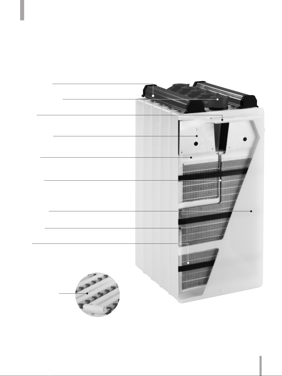
3.1. Plate assembly
The nickel-cadmium cell consists
of two groups of plates, one
containing nickel hydroxide
(the positive plate) and the other
containing cadmium hydroxide
(the negative plate).
The active materials of the Saft
Sunica.plus pocket plate have
been specially developed and
formulated to improve its cycling
ability, a specific need for
photovoltaic applications. These
active materials are retained in
pockets formed from nickel
plated steel which is double
perforated by a patented
process. The pockets are
mechanically linked together, cut
to the size corresponding to the
plate length and compressed to
the final plate dimension. This
process leads to a component
which is not only mechanically
very strong but also retains its
active material within a steel
boundary which promotes
conductivity and minimises
electrode swelling.
These plates are then welded to
a current carrying bus bar
assembly which further ensures
the mechanical and electrical
stability of the product.
Nickel-cadmium batteries have
an exceptionally good cycle life
because their plates are not
gradually weakened by repeated
cycling as the structural
component of the plate is steel.
The active material of the plate
is not structural, only electrical.
The alkaline electrolyte does not
react with steel, which means
that the supporting structure of
the Sunica.plus battery stays
intact and unchanged for the life
of the battery. There is no
corrosion and no risk of “sudden
death”.
In contrast, the lead plate of a
lead acid battery is both the
structure and the active material
and this leads to shedding of the
positive plate material and
eventual structural collapse.
3.2. Separation
The separator is a key feature
of the Sunica.plus battery. It is a
polypropylene fibrous material
which has been used and proven
by Saft in the Ultima ultra-low
maintenance product over more
than 20 years and has been
further developed for this
product to give the features
required. Using this separator,
the distance between the plates
is carefully controlled to give the
necessary gas retention to
provide the level of
recombination required.
By providing a large spacing
between the positive and
negative plates and a generous
quantity of electrolyte between
plates, the possibility of thermal
runaway, a problem with VRLA
cells, is eliminated.
7