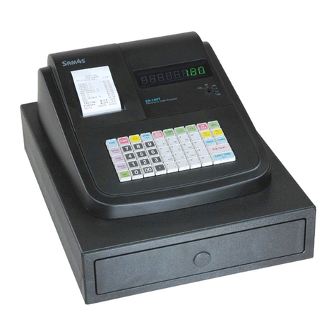
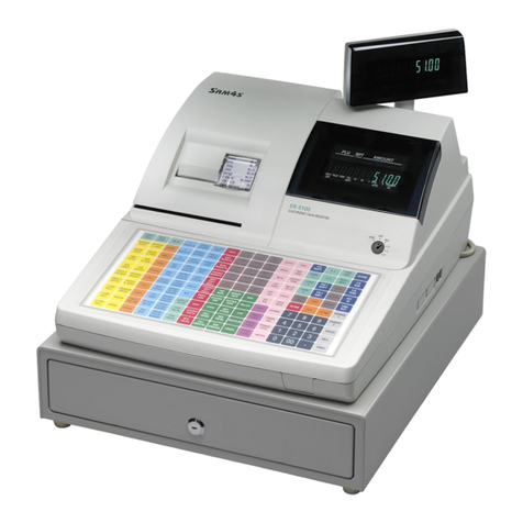
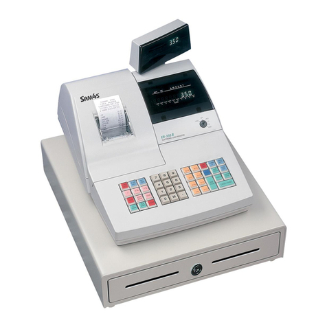
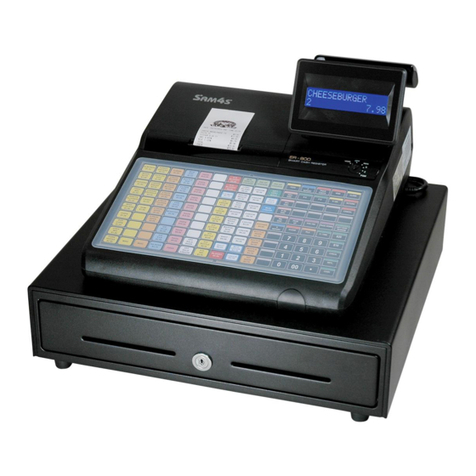
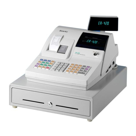
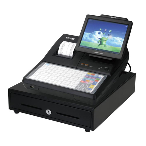
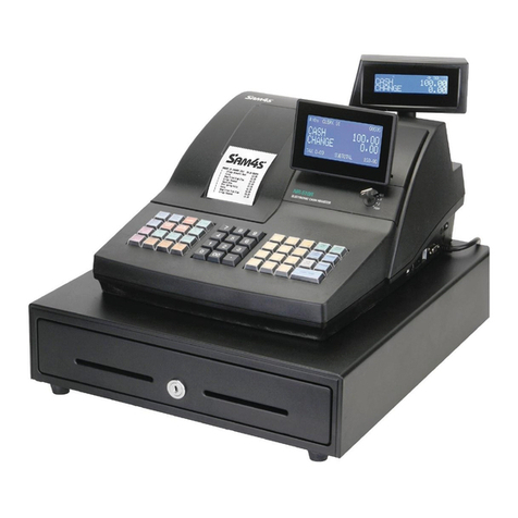
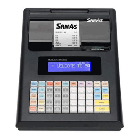
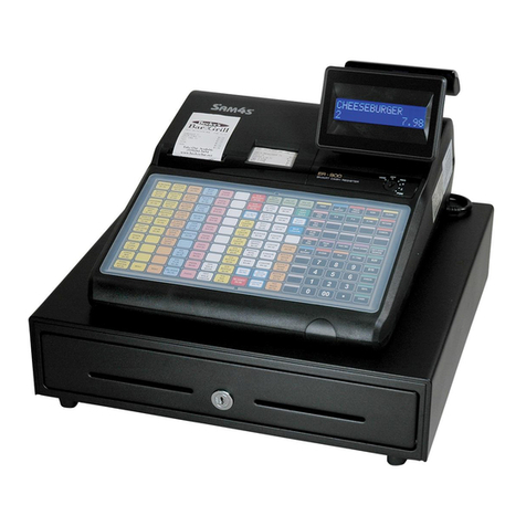
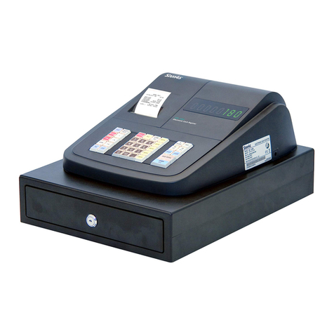
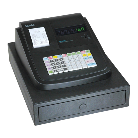
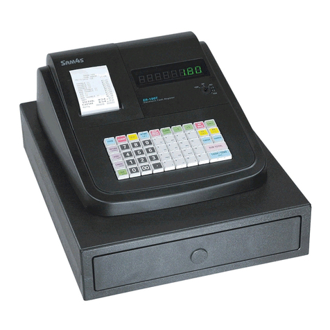
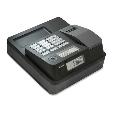
Sam4s ER-280 SERIES User manual

ELECTRONIC CASH REGISTER C O N T E N T S
ER-280 SERIES
ELECTRONIC CASH REGISTER
Manual
1. Precaution Statements
2. Product Specifications
3. Installation and Operation
4. Disassembly and Assembly
5. Troubleshooting
6. Exploded Views and Parts List
7. PCB Layout and Parts List
8. Block diagram
9. Wiring Diagram
10. Schematic Diagrams
SERVICE

About this Manual
This service manual describes how to perform
hardware service maintenance for the SAM4S
ER-280 Series Electronic Cash Register.
Notes
Notes may appear anywhere in the manual.
They describe additional information about the
item.
Precaution symbols
. Indicates a Safety Precaution that applies to
this part component.
. Indicates the part or component is an
electro-statically sensitive device. Use caution
when handling these parts.

Copyright
200ⓒ7 by Shin Heung Precision.
All right reserved.
This manual may not, in whole or in part, be
copied, photocopied, reproduced, translated
or converted to any electronic or machine
readable from without prior written
permission of Shin Heung Precision .
SAM4S ER-280 SERIES
Service Manual First edition.
March 2007.
V1.0
Printed in KOREA

Overview of this ECR
This ECR is a microprocessor-based system, using a 16 bits microprocessor.
This service manual provides the technical information for many individual component systems, circuits and
gives an analysis of the operations performed by the circuits. If you need more technical information, please
contact our service branch or R&D center. Schematics and specifications provide the needed information for the
accurate troubleshooting.
All information in this manual is subject to change without prior notice. Therefore, you must check the
correspondence of your manual with your machine. No part of this manual may be copied or reproduced in any
form or by any means, without the prior written consent of Shin Heung Precision.
Note: Before using this Electronic Cash Register (ECR) for the first time, leave it powered on in the REG
mode for at least 24 hours. This allows the MS Lithium battery, which maintains the memory of the
ECR while the power is off, to charge completely.
“Proper disposed of batteries is required. Refer to your local codes for disposed requirements.”

SAM4S ER-280 SERIES 1-1
1 Precaution Statements
Follow these safety, servicing and ESD precautions to prevent damage and to protect against potential hazards
such as electrical shock.
1-1 Safety Precautions
1. Be sure that all built-in protective devices are
replaced. Restore any missing protective
shields.
2. When reinstalling the chassis and its
assemblies, be sure to restore all protective
devices, including nonmetallic control knobs and
compartment covers.
3. Make sure there are no cabinet openings
through which people - particularly children -
might insert fingers and contact dangerous
voltages.
Such openings include excessively wide cabinet
ventilation slots and improperly fitted covers and
drawers.
4. Design Alteration Warning:
Never alter or add to the mechanical or
electrical design of the ECR. Unauthorized
alterations might create a safety hazard. Also,
any design changes or additions will void the
manufacturer’s warranty.
5. Components, parts and wiring that appear to
have overheated or that are otherwise damaged
should be replaced with parts that meet the
original specifications. Always determine the
cause of damage or over- heating, and correct
anypotentialhazards.
6. Observe the original lead dress, especially near
the following areas: sharp edges, and especially
the AC and high voltage supplies.
Always inspect for pinched, out-of-place, or
frayed wiring. Do not change the spacing
between components and the printed circuit
board. Check the AC power cord for damage.
Make sure that leads and components do not
touch thermally hot parts.
7. Product Safety Notice:
Some electrical and mechanical parts have
special safety-related characteristics which
might not be obvious from visual inspection.
These safety features and the protection they
give might be lost if the replacement component
differs from the original - even if the
replacement is rated for higher voltage, wattage,
etc.
Components that are critical for safety are
indicated in the circuit diagram by shading, ( )
or ( ). Use replacement components that have
the same ratings, especially for flame
resistance and dielectric strength specifications.
A replacement part that does not have the
same safety characteristics as the original might
create shock, fire or other hazards.
CAUTION
Danger of explosion if battery is incorrectly replaced.
Replace only with the same or equivalent type
recommended by the manufacturer.
Dispose used batteries according to the
manufacturer’s instructions.
ATTENTION
ll y a danger d’explosion s’il y a remplacement
incorrect de la batterie.
Remplacer uniquement avec une batterie du même
type ou d’un type équivalent recommandé par le
constructeur.
Mettre au rebut les batteries usagées conformément
aux instructions du fabricant.

1 Precaution Statements
1-2 SAM4S ER-280 SERIES
1-2 Servicing Precautions
WARNING: First read the-Safety Precautions-section of this manual. If some unforeseen circumstance creates
a conflict between the servicing and safety precautions, always follow the safety precautions.
WARNING: An electrolytic capacitor installed with the wrong polarity might explode.
1. Servicing precautions are printed on the cabinet.
Follow them.
2. Always unplug the units AC power cord from the
AC power source before attempting to:
(a) Remove or reinstall any component or
assembly
(b) Disconnect an electrical plug or connector
(c) Connect a test component in parallel with an
electrolytic capacitor
3. Some components are raised above the printed
circuit board for safety. An insulation tube or tape
is sometimes used. The internal wiring is
sometimes clamped to prevent contact with
thermally hot components. Reinstall all such
elements to their original position.
4. After servicing, always check that the screws,
components and wiring have been correctly
reinstalled. Make sure that the portion around the
serviced part has not been damaged.
5. Check the insulation between the blades of the
AC plug and accessible conductive parts
(examples: metal panels and input terminals).
6. Insulation Checking Procedure:
Disconnect the power cord from the AC source
and turn the power switch ON. Connect an
insulation resistance meter (500V) to the blades
of AC plug.
The insulation resistance between each blade of
the AC plug and accessible conductive parts
(see above) should be greater than 1 mega ohm.
7. Never defeat any of the B+ voltage interlocks.
Do not apply AC power to the unit (or any of its
assemblies) unless all solid-state heat sinks are
correctly installed.
8. Always connect an instrument’s ground lead to
the instrument chassis ground before connecting
the positive lead ;
Always remove the instrument’s ground lead last.
1-3 Precautions for Electrostatic Sensitive Devices (ESDs)
1. Some semiconductor (solid state) devices are
easily damaged by static electricity. Such
components are called Electrostatic Sensitive
Devices (ESDs); examples include integrated
circuits and some field-effect transistors. The
following techniques will reduce the occurrence of
component damage caused by static electricity.
2. Immediately before handling any semiconductor
components or assemblies, drain the
electrostatic charge from your body by touching
a known earth ground. Alternatively, wear a
discharging wrist-strap device. (Be sure to
remove it prior to applying power - this is an
electric shock precaution.)
3. After removing an ESD-equipped assembly,
place it on a conductive surface such as
aluminum foil to prevent accumulation of
electrostatic charge.
4. Do not use freon-propelled chemicals. These can
generate electrical charges that damage ESDs.
5. Use only a grounded-tip soldering iron when
soldering or unsoldering ESDs.
6. Use only an anti-static solder removal device.
Many solder removal devices are not rated as
anti-static; these can accumulate sufficient
electrical charge to damage ESDs.
7. Do not remove a replacement ESD from its
protective package until you are ready to install
it. Most replacement ESDs are packaged with
leads that are electrically shorted together by
conductive foam, aluminum foil or other
conductive materials.
8. Immediately before removing the protective
material from the leads of a replacement ESD,
touch the protective material to the chassis or
circuit assembly into which the device will be
installed.
9. Minimize body motions when handling
unpackaged replacement ESDs. Motions such as
brushing clothes together or lifting a foot from a
carpeted floor can generate enough static
electricity to damage an ESD.
SAM4S ER-280 SERIES 2-1
2 Product Specifications
Specifications are correct at the time of printing. Product specifications are subject to change without notice.
See below for product specifications.
2-1 Specifications
Item Description Remark
Processor •MITSUBISH M16C/80 Group M30800SFP (16 Bit)
Memory
•RAM (System Memory)
SRAM (K6T4008C2E) : 4MBITs (Default)
SRAM (K6T4008C2E) : 4MBITs (Option)
•ROM (Selectable)
FLASH ROM(AM29F800) : 8MBITs
EPROM(27C4001) : 4MBITs
•FISCAL ROM
EPROM(27C1001) : 1MBITs (Default)
EPROM(27C2001) : 2MBITs (Option)
•SD CARD
SD / SDIO Protocol V1.0 Compatible, Recommend 1Gbyte
Battery
•Type : MS Lithium, 3.0V 11mAh
•Part Name : MS920S
•Charging Time : 24 Hours
•Life : 3 Years
Data Storage •60 Days (When battery is Full charged)
Serial
(RS-232C)
•Flow Control :
① DTR / DSR : H/W Flow Control
•Baud Rate : 1200 / 2400 / 4800 / 9600 / 19200 bps
•Connector : DB9P Female * 1 (Default)
: DB9P Female * 2 , RJ-11 (Option)
•Voltage Supply : VCC(+5V/150mA) supplies at 9Pin of Connector.
I/F PBA
Interface
USB
•Transfer Type : Bulk
•Speed : 12Mbps (Full Speed)
•Power : Self-Powered
I/F PBA
Option
MCR
•2 Track : Track #1,#2 or Track #2,#3 / ISO7810,7811,7812
•Reading Method : F2F
•Operating Speed : 10 ~ 150 [Cm/Sec]
Option
Display •Operator Display : 10 Digits VFD or LCD(16 * 2Line Character Type)
•Customer Display : 10 Digits VFD
Keyboard •49-Key (Raised Type): ER-280 Series
•49-Key (Flat Type) : ER-285 Series
Drawer •5B5C / 4B8C Aplus-DRAWER
Power Consumption •Regularity : Approx. 20W
Power Requirement •AC 120V 60Hz, 230V 50Hz
Environment Condition •Temperature : 0℃~ 40℃
•humidity : 30% ~ 80% RH
Dimensions(mm) •430(W) X 450(D) X 242(H) With Middle Drawer
Weight •10.3kg (Set Only), 11.5kg (with Packing) With Middle Drawer

2. Product Specifications
2-2 SAM4S ER-280 SERIES
2-2 Dimensions
2-2-1 Appearance Dimensions (mm)
Figure2-1 Dimensions
2-2-2 Location Feature
Figure2-2 Location Feature
① Printer Cover
② Key Board (Raised or Flat type)
③ Drawer
④ Customer 10-Digits VFD Display
⑤ Operator Display (10-Digits VFD) or 16x2 line LCD
⑥ Mode Key
⑦ Interface Cover
⑧ SD-Card (Option)
⑨ MSR (Option)

2. Product Specifications
SAM4S ER-280 SERIES 2-3
2-3 Printer Specification
2-3-1 Printer Specification
Item Description Remark
Model •LTP8235(SII)
Print Method •Thermal Dot Line Printing
Total Number of Dots •288 Dots
Printing Format Dot Pitch •Vertical : 0.169 mm
•Horizontal : 0.169 mm
Printing Speed •50mm/Sec, 13Line/Sec
Printing Direction •Unidirectional friction feed
Feeding Method •Friction Feed
Minimum Feed Pitch •0.169 mm
Paper Feeding
Feeding Speed •50 mm/Sec
Power Voltage •8.0V Head/Motor
Power Supply Volt Circuit Input Voltage •5V Head Control/Sensor
Heat Element Density •6 Dots/mm (150 dpi)
Total Head Elements •288 Dots/Dot Line
Printer Head
Available Printing Width •48 mm
Line Feed Motor •4-Phase Bi-Polar Stepping Motor
Head Temperature •Thermistor
Sensor Paper-End Sensor •Reflecting Photo Sensor
Reliability Life •50km / 5×10⁷pulse
Dimension (mm) •38.0 (W) ×72.0 (D) ×15.6 (H)
Weight •Approx. 50 g
Table 2-2 Thermal Printer Specification
2-3-2 Paper Specification
Item Description Remark
Paper Type •Single-ply Thermal Paper Roll
Paper Size •57.5 mm±0.5 mm (Width) ×diameter Ø 70 mm or less
Table 2-3 Paper Specifications
2-3-3 Character Specification
Item Description Remark
Character Structure •8(W) ×17(H) Font (Including a horizontal)
Character Size •1.33 mm(W) ×2.83 mm(H)
Column Pitch •1.5 mm
Line Pitch •3.67 mm (Including 5-dot line spacing)
Number of Column •32 (8×17 Dots/Character)
Table 2-4 Character Specification

2. Product Specifications
2-4 SAM4S ER-280 SERIES
2-4 Power Specification
Item Description Remark
Input Voltage
& Current
•U.S.A : AC 120V, 60Hz (Min : 102V, Max : 138V)
•Europe : AC 220V/240V, 50Hz (Min : 195.5V, Max : 264.5V) Max & Min : ±15%
Power Consumption •Regularity : Approx. 20W
Output Voltage •AC 19V 2.3A (Wire Color : Blue-Blue)
•AC 24V 0.15A (Wire Color : Red-Red) Power Transformer
Output
Table 2-5 Power Specification
2-5 Interface Specification
2-5-1 RS-232C Serial Interface
2-5-1-1 Specification
Item Description Remark
Data Transmission •Serial
Synchronization •Asynchronous
Hand Shaking
(Flow Control) •H/W : DTR / DSR
Signal Level •Logic”1” (MARK) : -3V ~ -15V
•Logic”0” (SPACE) : +3V ~ +15V
Baud Rate •9600 bps
Data Word Length •8 Bit
Parity •None
Connector •DB9P Female and RJ-45 connector (I/F PBA Side) RJ-45 Option
Voltage Supply •VCC(+5V/150mA) is supplied at 9Pin of D-SUB Connector.
•VCC(+5V/150mA) is supplied at 1Pin of RJ-45 Connector. For Bar Code Reader
or other devices
Table 2-6 RS-232C Specification
2-5-1-2 Signal Description (DSUB 9PIN Female)
Pin No. Signal Name Signal Direction Function
BODY Frame GND - Frame Ground
2 RXD Input Receive Data
3 TXD Output Transmit Data
4 DTR Output
This Signal indicates whether the ECR(ER-260) is busy. (H/W flow control)
① MARK(Logic1) : The ECR is busy
② SPACE(Logic0) : The ECR is not busy
③ The host transmits a data to the ECR, after confirming this signal.
5 Signal GND - Signal Ground
6 DSR Input
This signal indicates whether the host computer or receipt printer can receive data.
(H/W flow control)
① MARK(Logic1) : The host can receive a data.
② SPACE(Logic0) : The host can not receive a data
③ The ECR transmits a data to the host or receipt printer, after confirming this signal.
9 VCC Output VCC(+5V/150mA) is supplied at 9Pin of D-SUB Connector. *Caution*
Table2-7 RS-232C Signal Description

2. Product Specifications
SAM4S ER-280 SERIES 2-5
2-5 Interface Specification
2-5-1-3 Signal Description (RJ-11 Connector)
Pin No. Signal Name Signal Direction Function
1 VCC Output VCC(+5V/150mA) is supplied at 9Pin of D-SUB Connector.
2 DSR Input
This signal indicates whether the host computer or receipt printer can receive data.
(H/W flow control)
④ MARK(Logic1) : The host can receive a data.
⑤ SPACE(Logic0) : The host can not receive a data
⑥ The ECR transmits a data to the host or receipt printer, after confirming this signal.
3 TXD Output Transmit Data
4 RXD Input Receive Data
7 Signal GND - Signal Ground
8 DTR Output
This Signal indicates whether the ECR(ER-260) is busy. (H/W flow control)
④ MARK(Logic1) : The ECR is busy
⑤ SPACE(Logic0) : The ECR is not busy
⑥ The host transmits a data to the ECR, after confirming this signal.
Table2-8 RS-232C Signal Description
Caution: The VCC is supplied for the barcode or device power source. If the Total Power Consumption
of the attached devices is exceeded the specification(150mA), the system stops the VCC of
DSUB Connector(Serial#1,Serial#2) and RJ-11 Connector(Serial#3)
Caution: If the device with 5V/150mA is connected to Serial#1, the VCC of Serial#2,Serial#3 can not use.
2-5-1-4 H/W Flow Control Timing
When DTR/DSR flow control is select, before transmitting a data, the ECR checks whether the host is BUSY
or not.
If the host is BUSY, ECR does not transmit a data to the host. If the host is not BUSY, ECR transmits a data to
the Host.
The host is the same.

2. Product Specifications
2-6 SAM4S ER-280 SERIES
2-5 Interface Specification
2-5-1-5 Cable Connection (DSUB 9 PIN FEMALE TYPE)
7
8
4
5
1
2
)RSD(6
)C.N(7
)DXT(3
)RTD(4
)G.F(
)C.N(1
ELAMEF
6
3)DXR(2
)G.S(5
)C.N(8
CP
NIP9EDIS
trohS)
ni
P8,6
(
&
)niP7,
4(
)RSD(6
)C.N(7
)DX
T(3
)RTD(
4
ELAM
)
G
.
F(
)C.N(
1
ELAM
D'BNORCE
ELAMEF
ROTCENNOC
)
D
X
R
(
2
)G.S(5
)C.N(8
RCE
NIP9EDIS
)C.PotR.C.E(tuoyaLelbaC
ecafretnIlaireSC232-SR
CP
ROTCENNOC
Figure2-3 RS232C Cable Connection (9Pin to 9Pin)
)RSD(6
)STR(7
)RSD(6
)G.S(7
)DXT(3
)RTD(4
)DXT(3
)STC(4
)G.F()G.F(
)C.N(1)C.N(1
ELAM ELAM
ELAMEF
)DXR(2
)G.S(5
)STC(8
)DXR(2
)STR(5
trohS)niP8,6(&)niP7,4(
6
7
3
4
1
D'BNORCE
RCE
NIP9EDIS
)RTD(02
2
5
8
RETNIRP/TSOH
NIP52EDIS
)P52TSOHotR.C.E(tuoyaLelbaC
ecafretnIlaireSC232-SR NIP52TSOH
ROTCENNOC
ELAMEF
ROTCEN
NOC
Figure2-4 RS232C Cable Connection (9Pin to 25Pin)

2. Product Specifications
SAM4S ER-280 SERIES 2-7
2-5 Interface Specification
2-5-1-6 Cable Connection (RJ-11 CONNECOR TYPE)
5(RTS)
6(CTS)
3(TXD)
7(S.GND)
2(DSR)
7(RTS)
8(CTS)
5(S.GND)
3(TXD)
4(DTR)
8(DTR)
4(RXD)
6(DSR)
2(RXD)
Figure2-5 RS232C Cable Connection (RJ-11 to 9Pin)
5(RTS)
7(S.GND)
8(DTR)
3(TXD)
4(RXD)
4(RTS)
7(S.GND)
6(DSR)
2(TXD)
3(RXD)
6(CTS)
2(DSR)
5(CTS)
20(DTR)
Figure2-6 RS232C Cable Connection (RJ-11 to 25Pin)
15m
15m

2. Product Specifications
2-8 SAM4S ER-280 SERIES
2-5 Interface Specification
2-5-2 USB Interface
2-5-2-1 Specification
Item Description Remark
Transfer Type •BULK
Data Signal •Bi-Direction, Half-Duplex
•Differential Signal Pair (D+ / D-)
Data Format •NRZI Format
•Zero bit Stuffing after 6 ones
Transceiver
•Differential Common Mode Range : 0.8~2.5[v]
•Differential Receive Sensitivity : 200 [mV]
•Single End Receive Threshold : 0.8~2.5[v]
Speed •12 Mbps
Power •Supply Self power
Cable & connector •Cable : 5m / 2m
•Connector : B type
Support Spec •USB Spec Version 1.1
Table 2-9 USB Specification
2-5-1-5 Cable Connection
HOST SIDE
"A" TYPE PLUG "B" TYPE PLUG
( USB I/F CABLE )
PRINTER
SIDE
Figure2-7 USB Cable Connection

SAM4S ER-280 SERIES 3-1
3 Installation and Operation
3-1 System Configuration
3-1-1 Configuration
Figure 3-1. System Configuration

3. Installation and Operation
3-2 SAM4S ER-280 SERIES
3-2 Installation
3-2-1 Paper Roll Installation
1. Remove the printer cover.(Fig 3-2 (A))
2. For proper feeding through the print head, cut or tear a straight even edge on the end of the paper roll.
(Be sure to remove any paper with glue residue.) Place the paper roll in the paper holder so that the
paper will feed from the bottom of the roll.(Fig 3-2 (B))
3. Insert the end of the paper into the paper slot.(Fig 3-2 (C))
4. Close the paper lever. ( ER-280 Series is possible to feed automatically when you rock the paper levers
and
insert paper.). (Fig 3-2 (D))
5. Replace the printer cover.(Fig 3-2 (E))
Figure 3-2. Paper Installation

3. Installation and Operation
SAM4S ER-280 SERIES 3-3
3-2 Installation
3-2-2 Take-Up Spool Installation
If you wish to use the printer to print a sales journal, insert the paper into the paper take※-up spool.
Wind the paper two or three turns around the spool shaft and install the spool in the mount
1. If you use the ER-280 Series with 1-station, refer to below figure. (Fig 3-3 (F))
2. If you use the ER-280 Series with 2-stations, refer to below figure. (Fig 3-3 (G))
Figure 3-3. Spool Installation

3. Installation and Operation
3-4 SAM4S ER-280 SERIES
3-2 Installation
3-2-3 RS-232C Serial Cable Installation
1.Open the I/F Door.
2.Connect the RS-232C serial cable to the RS-232C serial port on the rear side of ECR.
3.Secure the serial cable with screws.
4.Connector the other end of the RS-232C serial Cable to your host computer.
Figure 3-4. Cable Installation
3-2-4 Options
No. Item Description Remark
1 Water Proof Raised Keyboard (Option)
2 Memory SRAM 4MBITs (4MBITs * 1) On Main PBA
3 Pulley Winding Spool motor & Pulley Factory option
Table 3-1. Option
3-2-5 Supplies
No. Item Description Remark
1 Paper Roll 1 EA
2 Mode Key VD, REG, X, Z, P, C : NON FISCAL
REG, X, Z, P, C : FISCAL
3 User Manual 1 EA
4 Spool 1 EA
Table 3-2. Supplies

3. Installation and Operation
SAM4S ER-280 SERIES 3-5
3-3 Operation
Note: Before using this Electronic Cash Register (ECR) for the first time, leave it powered ON in the REG mode
for a at least 24 hours. This allows the Ms-Lithium battery, which maintains the ECR’s memory while the
power is OFF, to fully charge.
3-3-1 Mode Switch
The position of the Mode Key determines the action of the ECR. The modes are as shown in Table 3-3
Figure3-5 Mode Switch Table3-3 Mode Switch Function
The mode switch can be used to access the following key lock positions.
Mode Accessible Position Remark
VOID Void, Off, Register(REG), Manager(X)
REG Off, Register(REG)
X Off, Register(REG), Manager(X)
Z Off, Register(REG), Manager(X), Clear Totals(Z)
PGM Void, Off, Register(REG), Manager(X), Clear Totals(Z), Program(P)
S Void, Off, Register(REG), Manager(X), Clear Totals(Z), Program(P), Service Mode(S)
Table3-4 Key Function
Note : The Key can be removed from the key lock in the OFF or REGISTER position.
Mode Key Function
VOID VD Use to void (correct) items outside of a sale.
OFF - The Register is inoperable.
REG REG Use for normal registrations.
X X Use to read register reports and perform other manager functions.
Z Z Use to read register reports and reset totals to zero.
PGM P Use to program the register
S C Use for H/W tests and special setting.

3. Installation and Operation
3-6 SAM4S ER-280 SERIES
3-3 Operation
3-3-2 Key Board Matrix
1) 1-station model
Figure 3-6. 1-Station Model Key Board
2) 2-station model
Figure 3-7. 2-Station Model Key Board
Table of contents
Other Sam4s Cash Register manuals

Sam4s
Sam4s ER-900 Series User manual

Sam4s
Sam4s ER-285M User manual

Sam4s
Sam4s SAP-6600 User manual

Sam4s
Sam4s ER-390M User manual

Sam4s
Sam4s ER-5200M Owner's manual

Sam4s
Sam4s ER-180T User manual

Sam4s
Sam4s ER-180U Series User manual

Sam4s
Sam4s ER-420M Troubleshooting guide

Sam4s
Sam4s SPS-2000 User manual

Sam4s
Sam4s ER-380M User manual

Sam4s
Sam4s ER-390M User manual

Sam4s
Sam4s ER-380 Troubleshooting guide

Sam4s
Sam4s ER-650 User manual

Sam4s
Sam4s ER-900 Series User manual

Sam4s
Sam4s SPS-2000 User manual

Sam4s
Sam4s NR-500 Series Owner's manual

Sam4s
Sam4s ER-230 Series Troubleshooting guide

Sam4s
Sam4s ER-265 Owner's manual

Sam4s
Sam4s ER-260 SERIES User manual

Sam4s
Sam4s ER-920 Owner's manual