회전 중에 신체 일부가 끼일 위험이 있습니다.
몸의 일부나 의복이 말려들어가 부상당하는 위험이 있습니다.
!WARNING 경고
NC Rotary Table / Single Series
Instruction Manual
!WARNING 경고
!WARNING 경고
클램프볼트의 과도한 체결은 바디에 변형이 올 수 있으므로
정확한 토크로 조이십시오.
육각볼트 사이즈
/ Hex. bolt size
M10
M12
M16
M20
조임토크(N·m)
/ Tightening torque
33.8
58.9
146.3
294.3
!DANGER 위험
6
사용 전에 알아두셔야 할 것, 지켜야 할 것을 정리해 놓았습니다. 반드시 읽어주십시오.
이 취급설명서에 따르지 않은 경우에 발생하는 불량, 사고에 관한 책임은 지지 않습니다.
NC 로터리 테이블의 설치, 보수점검, 수리 시에는 반드시 설치기계 및 컨트롤러의 전원을 끄십시오.
테이블 회전시 회전영역 구간에 손을 넣지 마십시오.
클램프 볼트는 정확한 토크로 고정하십시오.
1. 사용 및 안전을 위하여
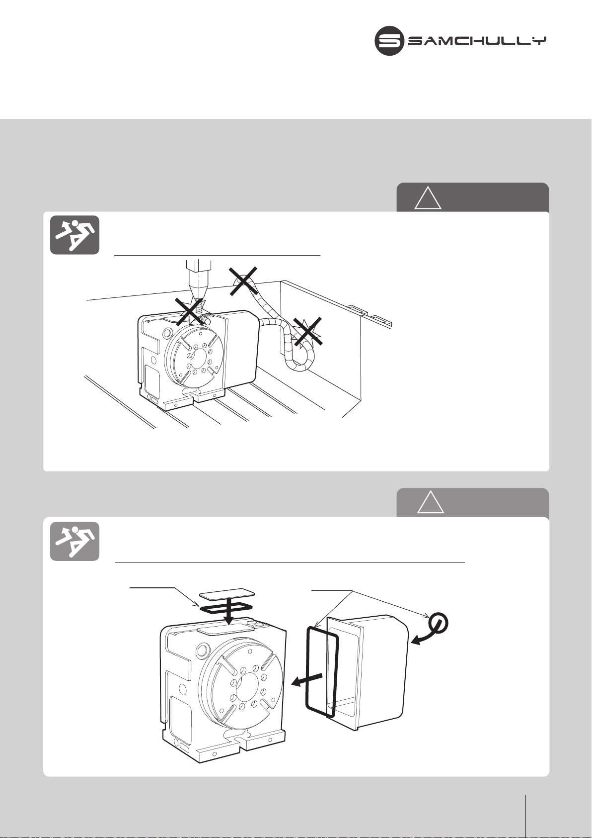
NC 로터리 테이블이 파손되고 공작물이 비산할 위험이 있습니다.
과대한 절삭력을 가하지 마십시오.
ON
OFF
ON
OFF
OFF
OFF
This section describes the matters that the user should know about and observe. Please read this document
carefully. The manufacturer does not bear any responsibility for any damage, accident or failure or malfunction
of the machine which may be caused by failure to observe the instructions
and descriptions given in this Operation Manual.
/ For Safe Operation
Make sure to shut off the power of the NC Rotary Table before installation, service,
maintenance, or repair work.
Be careful that no part of your body or clothing becomes caught in the machine,
as this may result in serious injury.
Bolts must be firmly tightened.
Otherwise, the NC Rotary Table may not be properly fixed
and the work piece may spring out.
Tighten the bolts to the specified torque.
Do not touch the rotating part while it is rotating.
Otherwise, your finger may be caught in it, resulting in serious injury.
Do not apply excessive cutting force.
Otherwise, the NC Rotary Table may be fractured and the work piece may fly off,
resulting in damage and/or injury.