6 S&C Instruction Sheet 663-500
Safety Precautions
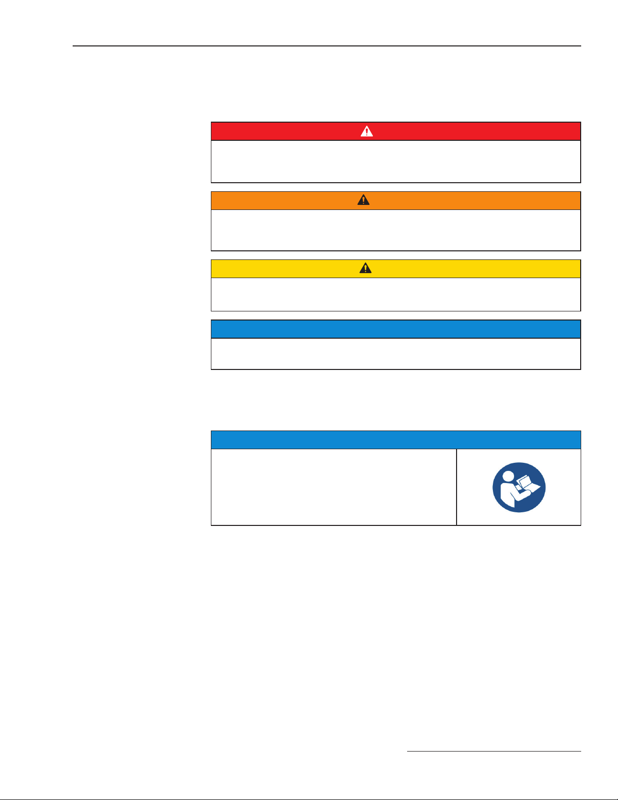
DANGER
S&C Source-Transfer PMH Pad-Mounted Gear operates at high-voltage.
Failure to observe the precautions below will result in serious personal injury
or death.
Some of these precautions may differ from company operating procedures and rules.
Where a discrepancy exists, follow your company’s operating procedures and rules.
1. QUALIFIED PERSONS. Access to S&C Source-
Transfer PMH Pad-Mounted Gear must be restricted
only to qualified persons. See the “Qualified Persons”
section on page 2.
2. SAFETY PROCEDURES. Always follow safe
operating procedures and rules.
3. PERSONAL PROTECTIVE EQUIPMENT. Always
use suitable protective equipment, such as rubber
gloves, rubber mats, hard hats, safety glasses, and
flash clothing, in accordance with safe operating
procedures and rules.
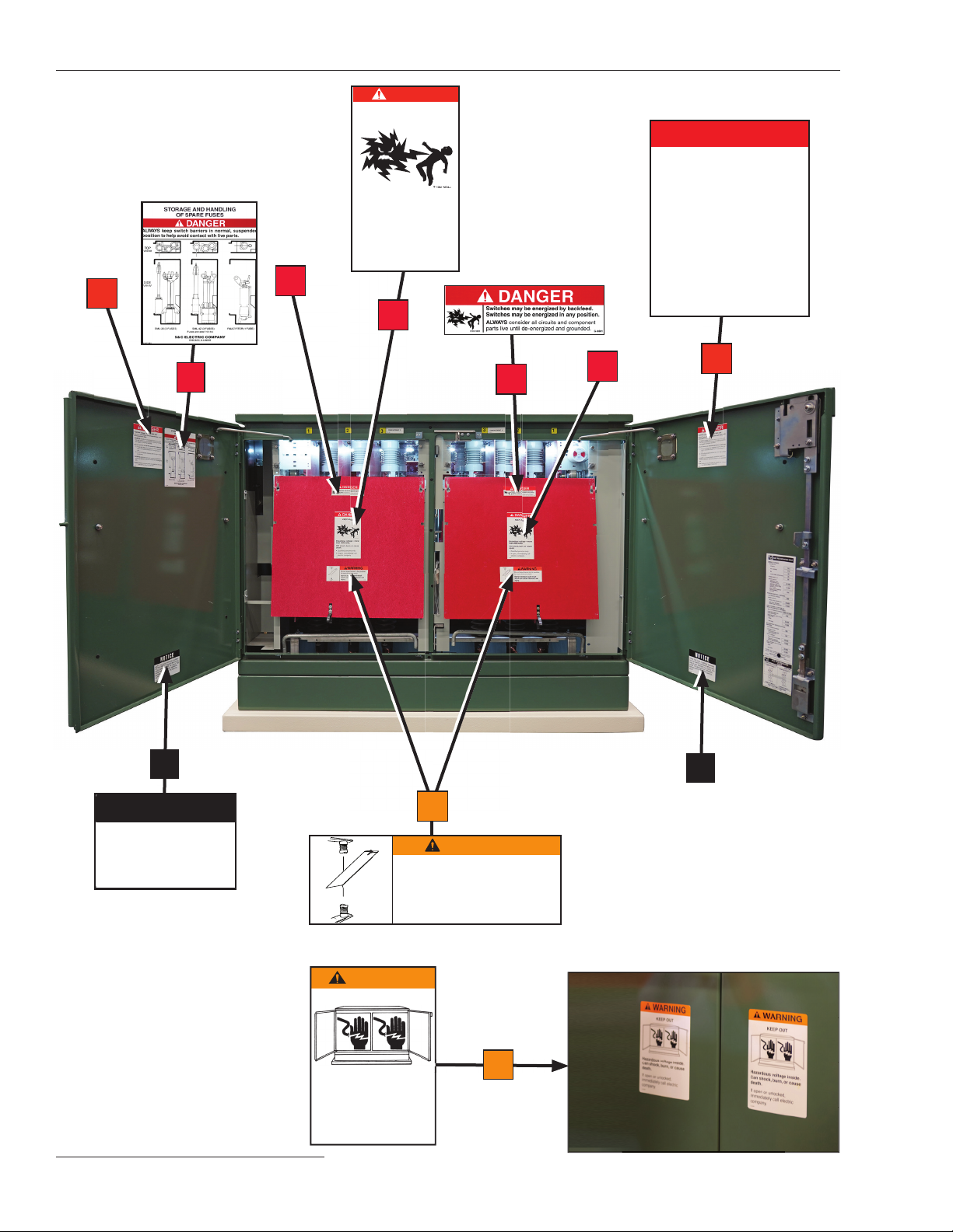
4. SAFETY LABELS. Do not remove or obscure any of
the “DANGER,” “WARNING,” “CAUTION,” or
“NOTICE” labels.
5. HIGH-VOLTAGE ISOLATION. Switch operators and
controls are isolated from high voltage in grounded,
metal-enclosed compartments. Access to these
components is controlled by padlockable covers,
which incorporate a nonremovable manual handle.
Other low-voltage components, such as meters,
selector switches, toggle switches, etc., are similarly
isolated.
6. TEST FOR VOLTAGE. Test for voltage using proper
high-voltage test equipment before touching any
device to be inspected, serviced, or repaired in the
high-voltage compartments.
7. ENERGIZED COMPONENTS. Always consider all
parts live until de-energized, tested, and grounded.
Voltage levels can be as high as the peak line-to-
ground voltage last applied to the unit. Units energized
or installed near energized lines should be considered
live until tested and grounded.
8. GROUNDING.
• Make sure the pad-mounted gear enclosure is
properly grounded to the station or facility ground.
• After the gear has been completely disconnected
from all sources of power and tested for voltage,
install suitable grounding cables in all compartments
before touching any device that is to be inspected,
replaced, serviced, or repaired in the high-voltage
compartments.
9. MAINTAINING PROPER CLEARANCE. Always
maintain proper clearance from energized
components.
10. SWITCH POSITION.
• Always confirm the Open/Close position of Mini-
Rupter® Switches by visually observing the position
of the switch blades.
• Switches may be energized by backfeed.
• Switches may be energized in any position.
11. PADLOCKS. Non-removable, manual handles in
high-voltage compartment doors and hinged-
padlockable covers, as well as hinged-bolted panels,
have provisions for padlocks that must be in place and
secured at all times unless work is being
performed inside the enclosure. Padlocks must be
installed and secured on manual switch operating
handles at alltimesunless theswitchis being operated.
12. KEY INTERLOCKS. Key interlocks (if applicable)
must be in place. Check the operating sequence of
key interlocks to verify proper sequencing. After the
switchgear is installed, destroy all duplicate keys or
make them accessible only to authorized persons so
the key interlock scheme will not be compromised.
Key interlocks are not security locks.
13. MECHANICAL CABLE INTERLOCKS. Mechanical
cable interlocks are provided to prevent access to
fuses unless the switch is open and to prevent
operation of stored-energy switch operators when the
enclosure door is open. Do not attempt to operate any
switch when the enclosure door is open. Periodically,
verify these interlocks are functional.
14. DO NOT APPLY UNDUE FORCE. Do not apply any
undue force when attempting to open a door. The use
of undue force may damage the door-latching
mechanism. If optional key interlocks are provided,
make certain the interlocks are in their correct
positions to allow door opening.
15. FUSE HANDLING.
• Make certain fuses are disconnected from all power
sources (including backfeed) before being inspected
or replaced.
• Always store fuses in a clean, dry location.
• Do not store end-fittings, holders, interrupting
modules, or fuses in termination compartments
unless the unit is equipped with the optional fuse-
storage feature (catalog number suffix “-E1,” “-E2,”
or “-E3”).
16. BACKFEED. Mini-Rupter Switches and fuses may be
energized by backfeed.