S&C VacuFuse II User manual

December 19, 2022
© S&C Electric Company 2022, all rights reserved Instruction Sheet 466-500
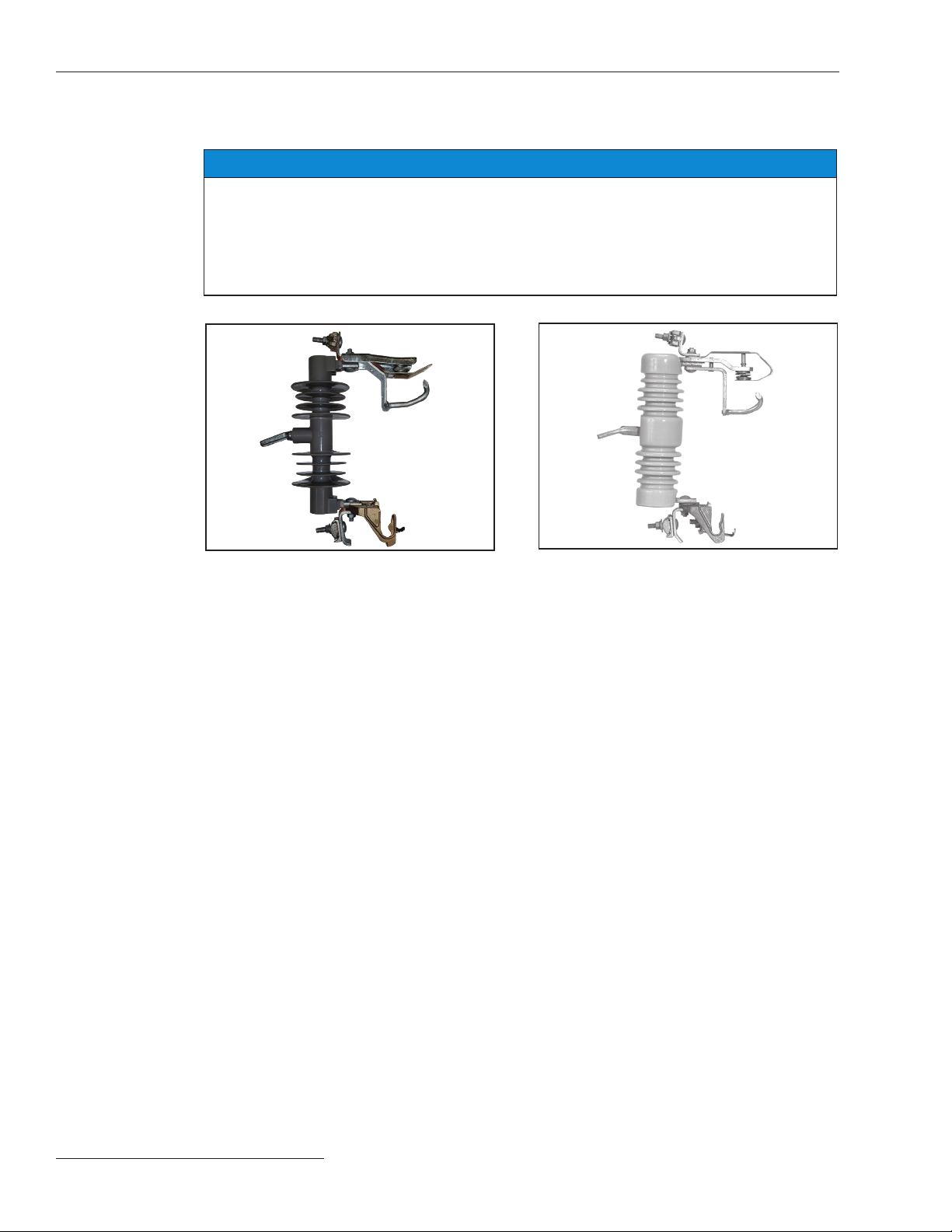
VacuFuse®II Self-Resetting Interrupter
Outdoor Distribution (12.47 kV through 27.0 kV)
For Overhead Distribution Transformer
Protection
Installation and Operation
Table of Contents
Introduction � � � � � � � � � � � � � � � � � � � � � � � � � � � � � 2
Qualified Persons ........................... 2
Read this Instruction Sheet ................... 2
Retain this Instruction Sheet .................. 2
Proper Application .......................... 2
Operating Considerations..................... 3
Warranty .................................. 3
Warranty Qualifications ...................... 4
Application Note ............................ 4
Safety Information� � � � � � � � � � � � � � � � � � � � � � � � 5
Understanding Safety-Alert Messages........... 5
Following Safety Instructions .................. 5
Replacement Instructions and Labels ........... 5
Location of Safety Labels ..................... 6
Safety Precautions ������������������������� 7
Shipping and Handling � � � � � � � � � � � � � � � � � � � � 8
Inspection ................................. 8
Packing ................................... 8
Handling .................................. 8
Storage ................................... 8
Returning ................................. 8
Before Starting � � � � � � � � � � � � � � � � � � � � � � � � � � 9
VacuFuse II Interrupter Parts .................. 9
Understanding the Closing Sequence ...........10
Understanding the LED Indicators and
POSITION Indicator .......................10
Installation � � � � � � � � � � � � � � � � � � � � � � � � � � � � � 12
Installing the Cutout Mounting .................12
Installing a VacuFuse II Interrupter into the
Cutout Mounting..........................13
Closing the VacuFuse II Interrupter into the
Cutout Mounting..........................14
Operation � � � � � � � � � � � � � � � � � � � � � � � � � � � � � � 15
If the VacuFuse II Self-Resetting Interrupter
Has Dropped Open .......................15
If Maintenance Is to Be Performed on the
Transformer .............................16
Opening and Closing the VacuFuse II Interrupter ...16
Removing the VacuFuse II Interrupter
from the Cutout Mounting...................18
Operation Using Loadbuster®—
The S&C Loadbreak Tool ...................19
Troubleshooting � � � � � � � � � � � � � � � � � � � � � � � � 23
Unable to Close a VacuFuse II Interrupter into its
Mounting. . . . . . . . . . . . . . . . . . . . . . . . . . . . . . . 23
In Mounting With Contacts Open .............. 23
Vacuum Interrupter Cannot Be Closed.......... 23

2 S&C Instruction Sheet 466-500
Introduction
WARNING
Only qualified persons who are knowledgeable in the installation, operation, and maintenance
of distribution fusing equipment, along with all associated hazards, may install, operate, and
maintain the equipment covered by this publication. A qualified person is someone who is
trained and competent in:
• The skills and techniques necessary to distinguish exposed live parts from nonlive parts
of electrical equipment
• The skills and techniques necessary to determine the proper approach distances
corresponding to the voltages to which the qualified person will be exposed
• The proper use of special precautionary techniques, personal protective equipment,
insulating and shielding materials, and insulated tools for working on or near exposed
energized parts of electrical equipment
These instructions are intended ONLY for such qualified persons. They are not intended to
be a substitute for adequate training and experience in safety procedures for this type of
equipment.
NOTICE
Thoroughly and carefully read this instruction sheet before installing or operating a
VacuFuse II Self-Resetting Interrupter. Become familiar with the Safety Information and
Safety Precautions on pages 5 through 7. The latest version of this publication is available
online in PDF format at sandc�com/en/support/product-literature/.
This instruction sheet is a permanent part of the VacuFuse II Self-Resetting Interrupter. Designate
a location where users can easily retrieve and refer to this publication.
WARNING
The VacuFuse II Self-Resetting Interrupter is only intended for the protection of distribution
transformers. The application must be within the ratings furnished for the equipment. Ratings
for the VacuFuse II Self-Resetting Interrupter are listed in the ratings table in Specification
Bulletin 466-31. They are also etched on the body of the interrupter.
Qualified
Persons
Read this
Instruction
Sheet
Retain this
Instruction
Sheet
Proper
Application

S&C Instruction Sheet 466-500 3
Introduction
The warranty and/or obligations described in S&C’s Price Sheet 150 “Standard Conditions of Sale
– Immediate Purchasers in the United States” (or Price Sheet 153, “Standard Conditions of Sale –
Immediate Purchasers Outside the United States”), plus any special warranty provisions, as set
forth in the applicable product-line specication bulletin, are exclusive. The remedies provided
in the former for breach of these warranties shall constitute the immediate purchaser’s or end
user’s exclusive remedy and a fulllment of the seller’s entire liability. In no event shall the seller’s
liability to the immediate purchaser or end user exceed the price of the specic product that gives
rise to the immediate purchaser’s or end user’s claim. All other warranties, whether express or
implied or arising by operation of law, course of dealing, usage of trade or otherwise, are excluded.
The only warranties are those stated in Price Sheet 150 (or Price Sheet 153), and THERE ARE NO
EXPRESS OR IMPLIED WARRANTIES OF MERCHANTABILITY OR FITNESS FOR A PARTICULAR
PURPOSE. ANY EXPRESS WARRANTY OR OTHER OBLIGATION PROVIDED IN PRICE SHEET 150
(OR PRICE SHEET 153) IS GRANTED ONLY TO THE IMMEDIATE PURCHASER AND END USER,
AS DEFINED THEREIN. OTHER THAN AN END USER, NO REMOTE PURCHASER MAY RELY
ON ANY AFFIRMATION OF FACT OR PROMISE THAT RELATES TO THE GOODS DESCRIBED
HEREIN, ANY DESCRIPTION THAT RELATES TO THE GOODS, OR ANY REMEDIAL PROMISE
INCLUDED IN PRICE SHEET 150 (OR PRICE SHEET 153.)
Warranty
For VacuFuse II Self-Resetting Interrupters with the Reclose feature: The VacuFuse II
Self-Resetting Interrupter is factory-set with a TCC curve, an open interval between the initial
trip (TCC0) and the rst test (TCC1) of 45 ±10 seconds, as well as a sequence reset time (between
30 seconds and 15 minutes.)
The sequence of operation is as follows: The interrupter will open once in response to its TCC
curve and will have an open interval lasting 45 ±10 seconds. Then, it will close, and its TCC curve
will again become active.
If the fault is still on the line, the VacuFuse II Self-Resetting Interrupter will lock open and drop
out. If fault current is not still on the line, the Sequence Reset Time timer will begin timing. If
another fault occurs during this time, the VacuFuse II Self-Resetting Interrupter will lock open
and drop out. If this timer expires without the VacuFuse II interrupter detecting fault current, the
VacuFuse II interrupter will reset to TCC0. Unless it has been specifically requested at the time of
order, TCC0 is the same curve as TCC1.
For Non-Reclosing VacuFuse II Interrupters: Non-reclosing VacuFuse II interrupters are
factory-set with a single TCC curve. The sequence of operation is as follows: The interrupter will
open once in response to its TCC curve and lock open. When sufficient energy has built up in the
device (45 ±10 seconds), the unit will drop out.
Operating
Considerations

4 S&C Instruction Sheet 466-500
Introduction
The seller’s warranties do not apply to VacuFuse II interrupters installed in other than a present-
production (“-R10” or “-R11”) S&C-provided cutout mounting.
NOTICE
When retrofitting VacuFuse II interrupters in an existing cutout mounting: To
ensure proper performance, VacuFuse II interrupters must only be installed in a present-
production (“-R10” or “-R11”) S&C-provided cutout mounting. See the example in Figure 1. An
example of an earlier-production S&C cutout mounting is shown in Figure 2. The warranty set
forth in S&C Price Sheet 150 does not apply to a VacuFuse II interrupter retrofitted in other
than a present-production (“-R10” or “-R11”) S&C-provided cutout mounting.
VacuFuse II Self-Resetting Interrupters are expressly designed for protecting solidly grounded
single-phase overhead distribution transformers with primary voltages of 7.2 kV to 15.5 kV. These
voltages correspond to the line-to-neutral voltages of single-phase transformers on systems rated
12.47 kV to 27.0 kV.
Warranty
Qualifications
Application
Note
Figure 1� A present-production (“-R10” or
“-R11”) S&C-provided Type XS Fuse Cutout
mounting�
Figure 2� An earlier-production (“-R9”) S&C
Type XS Fuse Cutout mounting� “-R8” and
earlier versions have a similar upper contact�

Safety Information
S&C Instruction Sheet 466-500 5
Several types of safety-alert messages may appear throughout this instruction sheet and on
labels and tags attached to the VacuFuse II Self-Resetting Interrupter. Become familiar with
these messages and the importance of these signal words:
DANGER
“DANGER” identifies the most serious and immediate hazards that will likely result in serious
personal injury or death if instructions, including recommended precautions, are not followed.
WARNING
“WARNING” identifies hazards or unsafe practices that can result in serious personal injury
or death if instructions, including recommended precautions, are not followed.
CAUTION
“CAUTION” identifies hazards or unsafe practices that can result in minor personal injury if
instructions, including recommended precautions, are not followed.
NOTICE
“NOTICE” identifies important procedures or requirements that can result in product or
property damage if instructions are not followed.
If any portion of this instruction sheet is unclear and assistance is needed, contact the nearest
S&C Sales Ofce or S&C Authorized Distributor. Their telephone numbers are listed on S&C’s
website sandc.com, or call the S&C Global Support and Monitoring Center at 1-888-762-1100.
NOTICE
Read this instruction sheet thoroughly and carefully before
installing the VacuFuse II Self-Resetting Interrupter.
If additional copies of this instruction sheet are required, contact the nearest S&C Sales Ofce,
S&C Authorized Distributor, S&C Headquarters, or S&C Electric Canada Ltd. The latest version
is available online in PDF format at sandc.com/en/Support/Product-Literature/.
It is important that any missing, damaged, or faded labels on the equipment be replaced
immediately. Replacement labels are available by contacting the nearest S&C Sales Office, S&C
Authorized Distributor, S&C Headquarters, or S&C Electric Canada Ltd.
Understanding
Safety-Alert
Messages
Following
Safety
Instructions
Replacement
Instructions
andLabels

Safety Information
6 S&C Instruction Sheet 466-500
Reorder Information for Safety Labels
Location Safety Alert Message Description Part Number
A
WARNING A VacuFuse® II Self-Resetting Interrupter must be dropped out from the cutout
mounting to be considered OPEN and de-energized.
Device may be energized from either side…
G-9842
DANGER
BTCC Curve (Label displaying the VacuFuse II interrupter’s protection curve) ●
●Contact the nearest S&C Sales Office.
B
A
Location of Safety Labels

S&C Instruction Sheet 466-500 7
Safety Precautions
DANGER
The VacuFuse II Self-Resetting Interrupter operates at high voltage. Failure to
observe the precautions below will result in serious personal injury or death.
Some of these precautions may differ from your company’s operating procedures
and rules. Where a discrepancy exists, follow your company’s operating procedures
and rules.
1. QUALIFIED PERSONS� Access to the VacuFuse II
Self-Resetting Interrupter must be restricted only to
qualified persons. See the “Qualified Persons”
section on page 2.
2. SAFETY PROCEDURES� Always follow safe
operating procedures and rules.
3. PERSONAL PROTECTIVE EQUIPMENT� Always
use suitable protective equipment, such as rubber
gloves, rubber mats, hard hats, safety glasses, and
flash clothing, in accordance with safe operating
procedures and rules.
4. SAFETY LABELS� Do not remove or obscure any
of the “DANGER,” “WARNING,” “CAUTION,” or
“NOTICE” labels and tags. Remove tags ONLY if
instructed to do so.
5. ENERGIZED COMPONENTS� Always consider all
parts live until de-energized, tested, and grounded.
6. OPERATING TOOLS� To close a VacuFuse II Self-
Resetting Interrupter, use a conventional insulated
hotstick or S&C Universal Pole and Pole Extension
fitted with a Talon™ Handling Tool or distribution
prong. An extendostick also can be used after
proper training and practice. When energized or
installed near energized lines, contacts should be
considered live until tested and grounded. The
VacuFuse II interrupter can be operated using
Loadbuster®— The S&C Loadbreak Tool attached
to a conventional insulated hotstick or S&C
Universal Pole.
7. MAINTAINING PROPER CLEARANCE� Always
maintain proper clearance from energized
components.
8. DO NOT DISASSEMBLE the VacuFuse II Self-
Resetting Interrupter. There are no customer-
serviceable parts inside the VacuFuse II interrupter,
and disassembling the VacuFuse II interrupter will
void the warranty.
9. VACUUM INTERRUPTER POSITION� Always
confirm the Open/Closed position of the VacuFuse
II Self-Resetting Interrupter’s vacuum interrupter by
observing the POSITION indicator on the bottom of
the unit. The manual operating lever will not move
when the position of the vacuum interrupter
changes.

8 S&C Instruction Sheet 466-500
Shipping and Handling
Inspection
Examine the shipment for external evidence of damage as
soon after receipt as possible, preferably before removal
from the carrier’s conveyance. Check the bill of lading to
make sure the listed shipping skids, crates, and containers
are present. If there is visible loss or damage:
1. Notify the delivering carrier immediately.
2. Ask for a carrier inspection.
3. Note the condition of shipment on all copies of the
delivery receipt.
4. File a claim with the carrier.
If concealed damage is discovered:
1. Notify the delivering carrier within 15 days of receipt of
shipment.
2. Ask for a carrier inspection.
3. File a claim with the carrier.
Packing
A complete VacuFuse II Self-Resetting Interrupter consists
of the following components:
• The VacuFuse II Self-Resetting Interrupter
• A present-production (“-R10”) Type XS Cutout Mounting
and miscellaneous mounting hardware for securing the
cutout mounting to the pole, if specied
Handling
NOTICE
DO NOT DROP the VacuFuse II Self-Resetting
Interrupter or subject any of its parts to undue stress
during installation. Only remove a VacuFuse II Self-
Resetting Interrupter from the carton immediately
before installation.
Storage
VacuFuse II Self-Resetting Interrupters are shipped
on pallets banded with plastic wrap. This packaging
is designed to protect the VacuFuse II interrupters
from freight damage. This packaging is not suitable for
outdoor storage because it can pool water and damage
VacuFuse II interrupters. After receipt, VacuFuse II
interrupters should be stored indoors in their shipping
packaging. Storing VacuFuse II interrupters outdoors in
the shipping packaging will void the warranty.
Returning
When returning the VacuFuse II Self-Resetting Interrupter
for any reason, place the VacuFuse II interrupter in
the original shipping carton to prevent damage during
shipment. If additional shipping cartons are required,
contact the nearest S&C Sales Ofce, S&C Authorized
Distributor, or S&C Headquarters.

S&C Instruction Sheet 466-500 9
VacuFuse II Interrupter Parts
Become familiar with the parts of the VacuFuse II Self-
Resetting Interrupter. See Figure 3.
Figure 3� An overview of the VacuFuse II Self-Resetting Interrupter�
POSITION indicator
CHARGING LED
Manual operating
lever
Hinge-end contact
Jaw-end contact
Pull-ring
Before Starting
Trunnion
READY TO CLOSE LED

10 S&C Instruction Sheet 466-500
Before Starting
Understanding the Closing Sequence
Note: The VacuFuse II Self-Resetting Interrupter is
shipped from the factory with the vacuum interrupter in
the Open position.
After closing the VacuFuse II Self-Resetting Interrupter
into the cutout mounting, the CHARGING LED will blink
at a 1-second interval as long as there is sufcient voltage
present at the cutout mounting and the vacuum interrupter
is open.
The READY TO CLOSE LED will steadily illuminate
when the VacuFuse II Self-Resetting Interrupter has har-
vested enough energy to close the vacuum interrupter and
when the manual operating lever is in the Down position.
The VacuFuse II Self-Resetting Interrupter requires
45 ± 10 seconds to harvest enough energy to close the
vacuum interrupter.
There are two ways to close the vacuum interrupter:
Option 1 – Automatic Delayed Close
Place the manual operating lever into the Up position prior
to closing the unit into the cutout mounting, or less than
35 seconds after the CHARGING LED has begun blinking.
When closed into the cutout mounting in this state, the
CHARGING LED will blink at a 1-second interval if there
is sufcient voltage present at the cutout mounting and
the vacuum interrupter is open. The unit will automati-
cally close the vacuum interrupter after 45 ± 10 seconds.
Option 2 – Manual Close
Place the manual operating lever into the Down position
prior to closing the unit into the cutout mounting, or less
than 35 seconds after the CHARGING LED has begun
blinking.
Wait until the READY TO CLOSE LED is solidly lit. At
that time, the unit can be closed manually by moving the
manual operating lever to the Up position. Three seconds
after the lever is moved to the Up position, the vacuum
interrupter will close.
Understanding the LED Indicators and
POSITION Indicator
LED Indicators
There are two LEDs on the base of the VacuFuse II
interrupter. See Figure 4.
The CHARGING LED is white and indicates the
VacuFuse II interrupter is harvesting energy to close the
Figure 4� The LEDs on the base of the VacuFuse II
interrupter�
CHARGING
LED
READY TO
CLOSE LED

S&C Instruction Sheet 466-500 11
Before Starting
vacuum interrupter. When the VacuFuse II interrupter is
powered, the CHARGING LED will start flashing at one
flash per second as long as sufficient voltage is present
at the cutout mounting and the vacuum interrupter is
open. When full charge is achieved, the CHARGING LED
will continue flashing, the READY TO CLOSE LED will
illuminate, and the CHARGING LED will keep blinking.
NOTICE
At least 4 amperes of primary current must be
flowing through the VacuFuse II Self-Resetting
Interrupter to power the control from its Sleep state.
When powered, the control will remain powered if
the current through the device does not fall below
4 amperes. If less than 4 amperes of primary current
are present, the VacuFuse II Self-Resetting Interrupter
will still respond properly to fault current.
POSITION Indicator
The POSITION indicator is located on the base of the
VacuFuse II interrupter’s housing. It contains a highly
reective visible red or green target that indicates the
position of the vacuum interrupter inside the VacuFuse II
Self-Resetting Interrupter. The target is green when the
vacuum interrupter is in the Open position and red when
the vacuum interrupter is in the Closed position. See
Figure 5 and Figure 6.
NOTICE
Catalog number option “-J1” reverses the colors of the
POSITION indicator to red for the Open position and
green for the Closed position. This option is available
to utilities that require reversed colors on their system.
Do not refer to the position of the manual operating lever
to know the position of the vacuum interrupter. When the
VacuFuse II interrupter trips in response to a fault, the lever
does not move, leaving the lever in the Up position when
the vacuum interrupter is in the Open position. Always
observe the POSITION indicator to know the position of the
VacuFuse II interrupter’s vacuum interrupter.
Figure 6� The vacuum interrupter in the Closed position�
POSITION
indicator in the
Closed (Red)
position
POSITION indicator
in the Open (green)
position
Figure 5� The vacuum interrupter in the Open position�

12 S&C Instruction Sheet 466-500
Installation
Carriage-bolt
Carriage bolt nut
Lockwasher
Mounting
bracket Overhead pole-
top mounting
center insert
External
tooth
lockwasher
Figure 7� Attaching an overhead pole-top style VacuFuse II
interrupter cutout mounting to the mounting bracket�
Installing the Cutout Mounting
If a VacuFuse II interrupter is ordered without a cutout
mounting, proceed to the “Installing a VacuFuse II
Interrupter into the Cutout Mounting” section on page 13.
Complete the following steps to install the cutout
mounting for the VacuFuse II Self-Resetting Interrupter:
STEP 1� Attach the VacuFuse II interrupter cutout
mounting to a suitable mounting bracket, as
illustrated in Figure 7. Tighten the carriage bolt
nut until snug but loose enough to permit pivot
adjustment. Note the placement of the external-
tooth lockwasher between the mounting
bracket and the center insert of the mounting.
Note: A mounting bracket suitable for crossarm,
pole, or wall mounting is furnished only if
specified through the addition of suffix “-B”
or “-C” to the VacuFuse II interrupter catalog
number.
STEP 2� Pivot the mounting to a position that will
provide maximum ease of operation and then
securely tighten the carriage-bolt nut.
STEP 3� Make electrical connections. When using
aluminum conductors, be sure to wire-brush
them and apply a coating of oxidation inhibitor
before inserting them into the mounting’s
connectors.

S&C Instruction Sheet 466-500 13
Installation
Installing a VacuFuse II Interrupter into the
Cutout Mounting
WARNING
Provide training to line crews on the use of both a
hotstick and an extendostick before installing or
operating the VacuFuse II Self-Resetting Interrupter.
The VacuFuse II interrupter is different from other
cutout-mounted devices. Failure to properly handle
a VacuFuse II interrupter with a hotstick and/or an
extendostick may lead to serious injury or death.
Complete the following steps to install a VacuFuse II
interrupter into a cutout mounting:
STEP 1� If using an existing S&C cutout mounting
or other approved cutout mounting: Visually
inspect the cutout mounting for damage or
excessive wear, particularly in the upper and
lower contact areas. If ANY damage is visible,
replace the cutout mounting before proceeding.
DO NOT install and/or energize a VacuFuse II
Self-Resetting Interrupter into a damaged
cutout mounting.
STEP 2� Installation Using Insulated Gloves: With
the manual operating lever in the Down
position, insert the VacuFuse II Self-Resetting
Interrupter into a 110-kV BIL or a 125/150-kV
BIL-rated mounting with gloved hands, as
shown in Figure 8.
STEP 3� Installation using the Talon™ Handling
Tool: Attach a Talon Handling Tool to a short
hotstick. Insert the curled prong of the Talon
tool into the lifting eye of the trunnion, and raise
the VacuFuse II interrupter into the mounting.
Rotate the hotstick counterclockwise 180 degrees
to disengage it. See Figure 9.
Figure 8� Guiding the trunnion into the hinge of the cutout
mounting using gloved hands�
Trunnion
Figure 9� Using a Talon tool during installation�

14 S&C Instruction Sheet 466-500
Installation
Closing the VacuFuse II Interrupter into the
Cutout Mounting
Complete the following steps to close a VacuFuse II Self-
Resetting Interrupter into its mounting:
NOTICE
Read the “Understanding the Closing Sequence”
section on page 10 before closing the VacuFuse II
Self-Resetting Interrupter into its cutout mounting.
STEP 1� Conrm the VacuFuse II Self-Resetting
Interrupter is in the Open position by viewing
its POSITION indicator. See the “Understanding
the LED Indicators and POSITION indicator”
section on page 10 for more information. Place
the manual operating lever in the correct
position for the closing sequence desired. See
the “Understanding the Closing Sequence”
section on page 10.
STEP 2� Stand rmly in front of and in line with the
cutout mounting. Do not operate standing
directly underneath the VacuFuse II Self-
Resetting Interrupter. If using an extendostick,
stand from 6 to 10 feet (1.8 to 3.1 m) away from
the pole.
STEP 3� Insert the straight prong of a Talon Handling
Tool or a distribution prong into the pull-ring.
STEP 4� Swing the VacuFuse II interrupter to within
approximately 45 degrees of the fully Closed
position, as shown in Figure 10.
STEP 5� While rmly gripping the stick, drive the
VacuFuse II interrupter closed with forward
force. Maintain the forward force until the
interrupter properly closes and latches into the
cutout mounting.
STEP 6� Disengage the prong from the pull-ring, taking
care to avoid pulling the VacuFuse II interrupter
open.
Figure 10� A VacuFuse II interrupter within approximately
45 degrees of the fully Closed position�
45°

S&C Instruction Sheet 466-500 15
Operation
If the VacuFuse II Self-Resetting Interrupter
Has Dropped Open
WARNING
The VacuFuse II Self-Resetting Interrupter is designed
to protect distribution transformers from internal and
external fault current. A VacuFuse II Self-Resetting
Interrupter found in the Open and Drop Out position
should not be closed until the cause of the fault current
has been determined and repaired. Closing without
repairing the fault could result in equipment damage,
injury, or death.
After responding to an overcurrent event, the VacuFuse II
interrupter’s vacuum interrupter will open and the
POSITION indicator will show a green target. If the over-
current event persists after the reclosing event, the unit
will lock out and drop out from the cutout mounting. Note
that non-reclosing VacuFuse II interrupters will lock out
and drop out from the cutout mounting every time the
device responds to an overcurrent event.
Follow these steps if the VacuFuse II Self-Resetting
Interrupter has operated and is in the Open and Drop
Out position:
STEP 1� Remove the VacuFuse II Self-Resetting
Interrupter from its mounting, if required by
utility practice, following the steps in the
“Removing the VacuFuse II Interrupter from
the Cutout Mounting” section starting on
page 18.
STEP 2� Determine and resolve the cause of the fault.
STEP 3� After the cause of the fault has been determined
and after any necessary repairs have been
completed, install the VacuFuse II Self-
Resetting Interrupter and close it into the
mounting following the steps described in the
“Installation” section starting on page 12.

16 S&C Instruction Sheet 466-500
Operation
Figure 11� The manual operating lever in the Up position�
Manual operating
lever
If Maintenance Is to Be Performed on the
Transformer
Follow these steps if maintenance is to be performed on the
transformer:
STEP 1� Open the vacuum interrupter inside the VacuFuse II
Self-Resetting Interrupter by moving the manual
operating lever to the Down position rmly using
thestraightprongoftheTalontooloradistribution
prong. See Figure 11.
STEP 2� After the VacuFuse II Self-Resetting Interrupter
opens and drops out (after approximately
1 minute and 45 seconds), remove the unit from its
mounting, if required by utility practice. Follow
the steps in the “Removing the VacuFuse II
Interrupter from the Cutout Mounting” section
starting on page 18. This creates a visible “open
gap” showing the transformer is isolated from the
feeder. Depending on your utility’s standard
practices, additional grounds may be required.
STEP 3� Follow your utility’s standard practice for
performing transformer maintenance. After any
necessary maintenance or repairs have been
completed, install the VacuFuse II Self-Resetting
Interrupter and close it into the mounting
following the steps described in the “Installation”
section starting on page 12.
Opening and Closing the VacuFuse II
Interrupter
WARNING
The VacuFuse II Self-Resetting Interrupter is designed
to protect distribution transformers from internal and
external fault current. A VacuFuse II interrupter found in
the Open and Drop Out position (POSITION indicator
displaying a green target) should NOT be closed until
the cause of the trip operation has been determined and
repaired. Closing without repairing the fault could result
in equipment damage, injury, or death.
The vacuum interrupter inside the VacuFuse II Self-Resetting
Interrupter can be opened using the yellow manual operat-
ing lever on the side of the VacuFuse II interrupter, with
or without power. The interrupter must be closed in the
cutout mounting with sufcient voltage present for at least
45 seconds before the vacuum interrupter can be closed by
moving the lever to the Closed position.

S&C Instruction Sheet 466-500 17
Operation
The VacuFuse II Self-Resetting Interrupter will “drop
out” of the cutout mounting after one minute when the
vacuum interrupter is in the Open position and the READY
TO CLOSE LED is lit.
To Open: Pull the yellow manual operating lever down
firmly using the straight prong of the Talon tool or a dis-
tribution prong. Remove the tool right away. The vacuum
interrupter inside the VacuFuse II interrupter will open,
and the POSITION indicator will show the green target.
After one minute and 45 seconds of the vacuum interrupter
in the Open position, the unit will drop out. See Figure 12.
To Close: Push the pull-ring of the yellow manual oper-
ating lever up firmly using the straight prong of the Talon
tool or a distribution prong. The vacuum interrupter inside
the VacuFuse II interrupter will close after 45 seconds of
sufficient voltage being present at the cutout mounting,
and the POSITION indicator will show the red target. See
Figure 13. If the VacuFuse II interrupter is inadvertently
closed into a fault, the vacuum interrupter will trip open
independently of any force still applied to the manual
operating lever.
To Reset the Manual Operating Lever After
Manually Closing into Fault Current: When the
VacuFuse II interrupter trips in response to a fault,
the lever does not move, leaving the lever in the
Up position when the vacuum interrupter is open. The lever
can be “reset” by operating it to the Down position while
the vacuum interrupter is open. When the lever is in the
Up position, the interrupter will automatically close the
next time it is pushed into the cutout mounting.
Note: After the interrupter drops open (either because
of a permanent fault or moving the manual operating lever
to the Down position and waiting for the unit to drop open),
it is necessary to wait at least 20 seconds before closing
the interrupter into the cutout mounting again. If the inter-
rupter is closed into the cutout mounting immediately
after a permanent fault, it will drop-out without closing.
This happens because of the interrupter interpreting that
it never dropped-out from the cutout mounting.
Figure 12� Operating the manual operating lever into the
Down position�
Manual operating
lever
Manual operating
lever
Figure 13� Operating the manual operating lever into the
Closed position�

18 S&C Instruction Sheet 466-500
Operation
Removing the VacuFuse II Interrupter from
the Cutout Mounting
WARNING
DO NOT attempt to remove a VacuFuse II Self-
Resetting Interrupter from its cutout mounting with
the vacuum interrupter in the Closed position. The
vacuum interrupter is in the Closed position when the
POSITION indicator at the base of the VacuFuse II
interrupter displays a red target. Removing the
VacuFuse II interrupter from its cutout mounting with
the vacuum interrupter in the Closed position may
cause arcing, equipment damage, serious injury, or
death.
Complete the following steps to remove the VacuFuse II
interrupter from its cutout mounting:
STEP 1� Open the vacuum interrupter inside the
VacuFuse II interrupter by pulling down on the
yellow manual operating lever. Conrm the
POSITION indicator at the base of the
VacuFuse II interrupter displays a green target.
STEP 2� Wait one minute and 45 seconds until the
VacuFuse II Self-Resetting Interrupter drops
out.
If the VacuFuse II Self-Resetting Interrupter
stays in its cutout mounting, confirm
the POSITION indicator at the base of the
VacuFuse II interrupter displays a green target.
Use the troubleshooting guide on page 23 to
determine the cause of the unit remaining in
the cutout mounting and the appropriate action
to take.
STEP 3� Removal Using Gloved Hands: Remove the
VacuFuse II Self-Resetting Interrupter from its
cutout mounting with gloved hands, as shown in
Figure 14.
STEP 4� Removal Using the Talon Handling Tool:
Attach a Talon Handling Tool to a short hotstick.
Insert the curled prong of the Talon tool into the
lifting eye of the trunnion, and raise the
VacuFuse II interrupter out of the mounting.
See Figure 9 on page 13.
Figure 14� Removing the VacuFuse II interrupter with
gloved hands�

S&C Instruction Sheet 466-500 19
Operation
Operation Using Loadbuster®—The S&C
Loadbreak Tool
If the VacuFuse II Self-Resetting Interrupter is in its cutout
mounting with the vacuum interrupter in the Closed
position and operating the manual operating lever to the
Open position does not work, or the VacuFuse II interrupter
is to be removed from its cutout mounting in the Closed
position for any other reason, it may be safely removed
using S&C’s Loadbuster tool. Following an opening
operation with the Loadbuster tool, the VacuFuse II
interrupter can be lifted out of the mounting with gloved
hands.
WARNING
DO NOT attempt to open a VacuFuse II Self-Resetting
Interrupter that is in the Closed position without using
a loadbreak tool such as S&C’s Loadbuster tool. An
arc started by opening a VacuFuse II Self-Resetting
Interrupter under load without a loadbreak tool can
cause equipment damage, serious injury, or death.
WARNING
DO NOT attempt to use a Loadbuster tool to open a
VacuFuse II Self-Resetting Interrupter while climbing
the pole. Engagement of a Loadbuster tool in this
position is difficult and may result in improper opening
operation, leading to arcing, faults, equipment
damage, serious injury, or death.
WARNING
Stay at least 5 feet (152 cm) below the VacuFuse II
interrupter when operating the Loadbuster tool from
a bucket truck. Operating the Loadbuster tool from
less than 5 feet away is difficult and may result in an
improper opening operation, leading to arcing, faults,
equipment damage, serious injury, or death.

20 S&C Instruction Sheet 466-500
Operation
Figure 15� A correct fastening approach�
Figure 16� A correct fastening approach�
Follow these steps when using S&C’s Loadbuster tool:
STEP 1� Check for proper resetting of the Loadbuster
tool by extending the tool about 3 inches
(76 mm) by hand. Throughout this travel, an
increasing spring resistance should be felt.
STEP 2� Fasten the Loadbuster tool to an S&C Universal
Pole not less than 6 feet (183 cm) long (8 feet
[244 cm] for catalog number 5400R3) with the
frame of the tool in line with the pole. As shown
in Figures 15 and 16, the Loadbuster tool must
be attached so it reaches across the front of the
VacuFuse II Self-Resetting Interrupter, and the
Loadbuster tool’s anchor must be hooked to the
attachment hook on the far side of the
VacuFuse II interrupter.
The Loadbuster tool should never be attached
with its anchor hooked on the closest side of
the VacuFuse II interrupter, as shown in
Figures 17 and 18 on page 21. Attaching the
tool in this manner will not only obscure the
operator’s line of vision, but it could also result
in bending stress on the tool, causing improper
disengagement.
STEP 3� Swing the Loadbuster tool toward the
VacuFuse II Self-Resetting Interrupter and pass
the Loadbuster pull-ring hook through the pull-
ring on the VacuFuse II Self-Resetting
Interrupter. The pull-ring latch will deect and,
upon complete entry of the pull-ring, will spring
back, locking the Loadbuster tool to the pull-
ring. The Loadbuster tool is now connected
across the upper contacts of the VacuFuse II
Self-Resetting Interrupter, as shown in
Figure 19 on page 22.
Other manuals for VacuFuse II
3
Table of contents
Other S&C Industrial Equipment manuals