June 1, 2021
© S&C Electric Company 2021, all rights reserved Instruction Sheet 461-519
TripSaver®II Cutout-Mounted Recloser
Outdoor Distribution (15.5 kV, 25 kV)
TripSaver®II Communications via Gateway
using the IEC 60870-5-104 Protocol
Installation, Operation, and Conguration
Table of Contents
Section Page Section Page
Introduction
Qualified Persons ........................... 2
Read this Instruction Sheet ................... 2
Retain this Instruction Sheet. . . . . . . . . . . . . . . . . . . 2
Video..................................... 2
Proper Application .......................... 2
Warranty .................................. 2
Safety Information
Understanding Safety-Alert Messages........... 3
Following Safety Instructions .................. 3
Replacement Instructions and Labels ........... 3
Location of Safety Labels ..................... 4
Safety Precautions ......................... 5
Shipping and Handling
Packing ................................... 6
Inspection ................................. 6
Handling .................................. 6
Storage ................................... 6
Returning ................................. 6
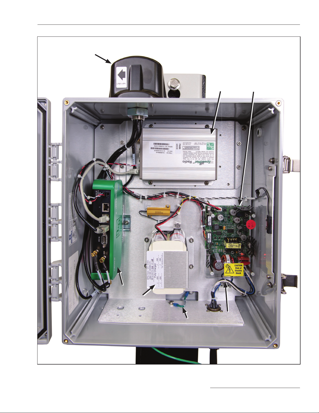
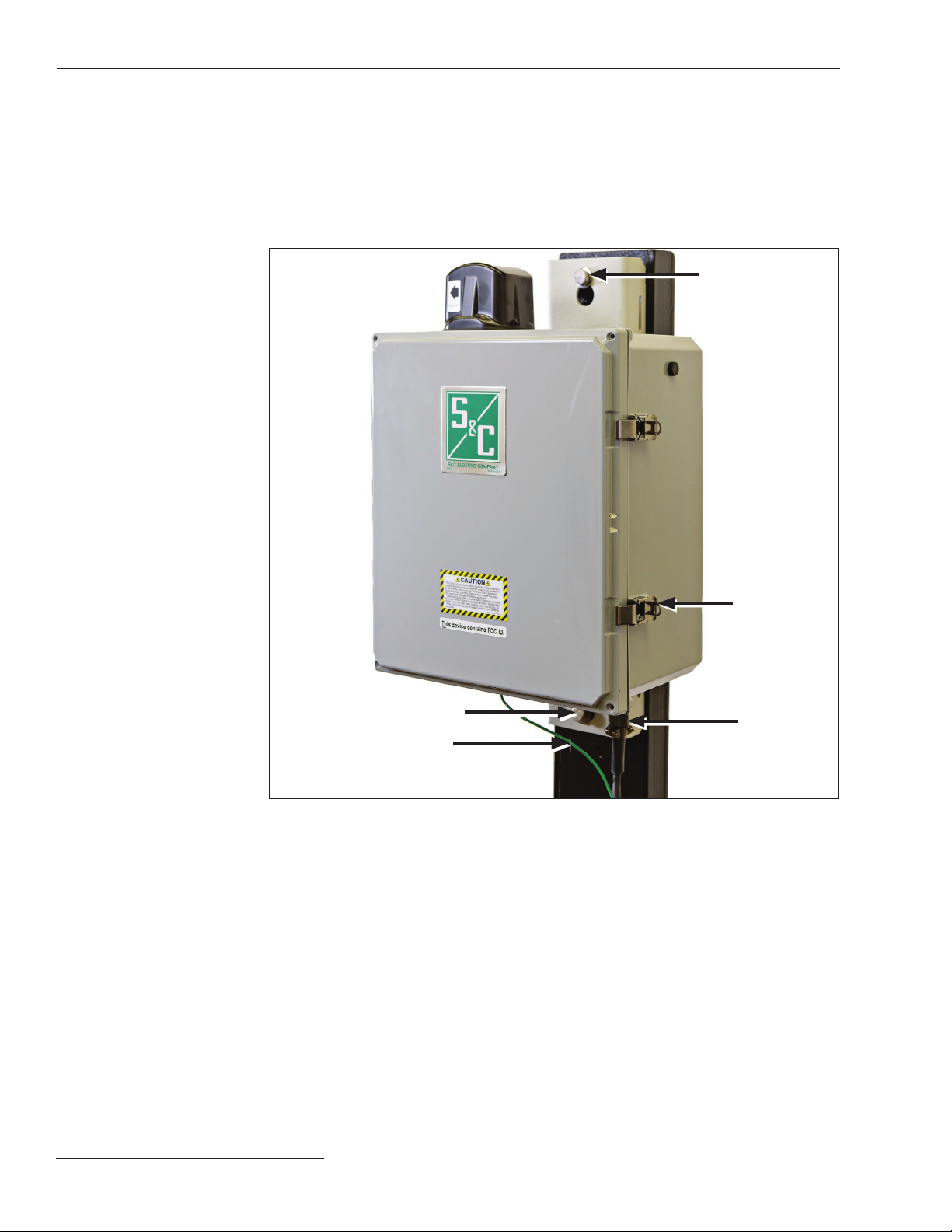
Mounting, Powering, and Securing the
Communications Gateway................... 7
Mounting the Communications Gateway to a Pole.. 8
Powering the Communications Gateway ......... 9
Securing the Communications Gateway ......... 9
Installing and Replacing a Radio
Installing a New Radio .......................10
Replacing a Radio ..........................11
Installing and Replacing a Backup Battery
Installing a New Battery ......................12
Replacing a Battery .........................13
Installing Remote Antenna Kits
Installing Remote Antenna Kit 903-002702-02/01 ..14
Installing Remote Antenna Kit 903-002701-01/02 ..15
Installing Remote Antenna Kit 903-002700-02/03 ..15
Installing and Replacing a Local Antenna
Installing Local Antenna 904-002450-02 .........16
Replacing a Local Antenna....................16
Configuring the Communications Gateway
Software User’s Guide .......................17
Enabling IEC 60870-5-104 Communication
Protocol in the Communications Gateway ......19
General Status ............................ 20
Gateway Settings ...........................21
Device Management........................ 37
Tri pSaver ®II Service Center Configuration
Software ................................. 38
Remote Drop Open......................... 40
Gang/Local Operation ...................... 42
User Roles ............................... 46
IEC 104 Setpoints ...........................47
IEC104 Controlling Station ................... 53
IEC104 Controlled Station ................... 53
Security Settings. . . . . . . . . . . . . . . . . . . . . . . . . . . 54
Profile ................................... 58
Diagnostics ............................... 58
Commissioning (Pairing) a TripSaver II Recloser
for Use with the Communications Gateway
Service Center Pairing a TripSaver II Recloser
with Firmware Version 1.9 or 1.8 ............ 60
Field Pairing a TripSaver II Recloser with Firmware
Version 1.6 or 1.7 Installed on the Utility Pole
and Powered by Line Current................61
Troubleshooting
Signal Interference ......................... 63
Pairing Process Takes Longer Than Expected ... 63
Quick Installation Checklist ................ 64
Appendix A
Interface Pinouts........................... 65
Power System Diagram ..................... 66
Understanding the Radio Mode ............... 66
Appendix B
Regulatory Information..................... 68