S&C Vista SD 101 User manual

February 1, 2021
© S&C Electric Company 2014-2021, all rights reserved Instruction Sheet 695-505
Vista®SD Underground Distribution Switchgear
Outdoor Distribution (17.5 kV and 29 kV)
With Visi-Gap®Load-Interrupter
Switches and Visi-Gap®
Fault Interrupters
Installation
Table of Contents
Section Page Section Page
Introduction
Qualified Persons . . . . . . . . . . . . . . . . . . . . . . . . . . . 2
Read this Instruction Sheet . . . . . . . . . . . . . . . . . . . 2
Retain this Instruction Sheet. . . . . . . . . . . . . . . . . . . 2
Proper Application . . . . . . . . . . . . . . . . . . . . . . . . . . 2
Warranty . . . . . . . . . . . . . . . . . . . . . . . . . . . . . . . . . . 3
Warranty Qualifications . . . . . . . . . . . . . . . . . . . . . . 3
Safety Information
Understanding Safety-Alert Messages. . . . . . . . . . . 4
Following Safety Instructions . . . . . . . . . . . . . . . . . . 4
Replacement Instructions and Labels . . . . . . . . . . . 4
Location of Safety Labels and Tags
Single-Way Vault-Mounted Style . . . . . . . . . . . . . 5
Multi-Way Vault-Mounted Style . . . . . . . . . . . . . . 6
Pad-Mounted Style . . . . . . . . . . . . . . . . . . . . . . . 7
Safety Precautions . . . . . . . . . . . . . . . . . . . . . . . . . 8
Shipping and Handling
Packing . . . . . . . . . . . . . . . . . . . . . . . . . . . . . . . . . . . 9
Inspection . . . . . . . . . . . . . . . . . . . . . . . . . . . . . . . . . 9
Handling . . . . . . . . . . . . . . . . . . . . . . . . . . . . . . . . . .10
Installation
Vault-Mounted Style
Switchgear Placement . . . . . . . . . . . . . . . . . . . . .12
Single-Way Vault-Mounted Style Unit
Installed Through 31½-Inch Manhole . . . . . . . . .13
Cables . . . . . . . . . . . . . . . . . . . . . . . . . . . . . . . . .14
Grounding . . . . . . . . . . . . . . . . . . . . . . . . . . . . . .15
Fault Indicators. . . . . . . . . . . . . . . . . . . . . . . . . . .15
Pad-Mounted Style
Switchgear Placement . . . . . . . . . . . . . . . . . . . . .16
Access to Interior . . . . . . . . . . . . . . . . . . . . . . . . .16
Cables . . . . . . . . . . . . . . . . . . . . . . . . . . . . . . . . .18
Attach Hinged-Roof Counterweights . . . . . . . . . 20
Install Termination Compartment
Cover Panels . . . . . . . . . . . . . . . . . . . . . . . . . . . .21
Grounding . . . . . . . . . . . . . . . . . . . . . . . . . . . . . .21
Fault Indicators. . . . . . . . . . . . . . . . . . . . . . . . . . 22
Closing the Doors and the Hinged Roof . . . . . . 23
Completing the Installation. . . . . . . . . . . . . . . . . 24
Appendix A
Routine Switchgear Testing . . . . . . . . . . . . . . . . . . 25
Dc Cable Testing and Fault Locating . . . . . . . . . . . 25
Very Low Frequency (VLF) Cable Testing . . . . . . . 26
Fault-Interrupter Testing . . . . . . . . . . . . . . . . . . . . . 27

2 S&C Instruction Sheet 695-505
Introduction
Qualified Persons WARNING
Only qualified persons who are knowledgeable in the installation, operation, and
maintenance of overhead and underground electric distribution equipment, along
with all associated hazards, may install, operate, and maintain the equipment
covered by this publication. A qualified person is someone who is trained and
competent in:
• The skills and techniques necessary to distinguish exposed live parts from nonlive
parts of electrical equipment
• The skills and techniques necessary to determine the proper approach distances
corresponding to the voltages to which the qualified person will be exposed
• The proper use of special precautionary techniques, personal protective
equipment, insulated and shielding materials, and insulated tools for working on
or near exposed energized parts of electrical equipment
These instructions are intended ONLY for such qualified persons. They are
not intended to be a substitute for adequate training and experience in safety
procedures for this type of equipment.
Read this
Instruction Sheet NOTICE
Thoroughly and carefully read this instruction sheet and all materials included
in the product’s instruction handbook before installing or operating Vista SD
Underground Distribution Switchgear. Familiarize yourself with the Safety Information
and Safety Precautions on pages 4 through 8. The latest version of this publication
is available online in PDF format at sandc.com/en/support/product-literature/.
Retain this
Instruction Sheet
This instruction sheet is a permanent part of your Vista SD Underground Distribution
Switchgear. Designate a location where you can easily retrieve and refer to this publication.
Proper Application WARNING
The equipment in this publication is only intended for a specific application. The
application must be within the ratings furnished for the equipment. Ratings for the
Vista SD Underground Distribution Switchgear are listed in the ratings table in
Specification Bulletin 695-33. The ratings are also on the nameplate affixed to the
product.

S&C Instruction Sheet 695-505 3
Introduction
Warranty The warranty and/or obligations described in S&C’s Price Sheet 150, “Standard Conditions
of Sale–Immediate Purchasers in the United States,” (or Price Sheet 153, “Standard
Conditions of Sale–Immediate Purchasers Outside the United States,”) plus any special
warranty provisions, as set forth in the applicable product-line specication bulletin,
are exclusive. The remedies provided in the former for breach of these warranties shall
constitute the immediate purchaser’s or end user’s exclusive remedy and a fulllment of
the seller’s entire liability. In no event shall the seller’s liability to the immediate purchaser
or end user exceed the price of the specic product that gives rise to the immediate pur-
chaser’s or end user’s claim. All other warranties, whether express or implied or arising
by operation of law, course of dealing, usage of trade or otherwise, are excluded. The
only warranties are those stated in Price Sheet 150 (or Price Sheet 153), and THERE
ARE NO EXPRESS OR IMPLIED WARRANTIES OF MERCHANTABILITY OR FITNESS
FOR A PARTICULAR PURPOSE. ANY EXPRESS WARRANTY OR OTHER OBLIGATION
PROVIDED IN PRICE SHEET 150 (OR PRICE SHEET 153) IS GRANTED ONLY TO THE
IMMEDIATE PURCHASER AND END USER, AS DEFINED THEREIN. OTHER THAN AN
END USER, NO REMOTE PURCHASER MAY RELY ON ANY AFFIRMATION OF FACT OR
PROMISE THAT RELATES TO THE GOODS DESCRIBED HEREIN, ANY DESCRIPTION
THAT RELATES TO THE GOODS, OR ANY REMEDIAL PROMISE INCLUDED IN PRICE
SHEET 150 (or PRICE SHEET 153).
Warranty
Qualifications
The seller’s standard warranty does not apply to components not of S&C manufacture
that are supplied and installed by the purchaser or to the ability of the seller’s equipment
to work with such components.

4 S&C Instruction Sheet 695-505
Safety Information
Understanding
Safety-Alert
Messages
Several types of safety-alert messages may appear throughout this instruction sheet and
on labels and tags attached to Vista SD Underground Distribution Switchgear. Familiarize
yourself with these types of messages and the importance of these various signal words:
DANGER
“DANGER” identifies the most serious and immediate hazards that will likely result in
serious personal injury or death if instructions, including recommended precautions,
are not followed.
WARNING
“WARNING” identifies hazards or unsafe practices that can result in serious personal
injury or death if instructions, including recommended precautions, are not followed.
CAUTION
“CAUTION” identifies hazards or unsafe practices that can result in minor personal
injury if instructions, including recommended precautions, are not followed.
NOTICE
“NOTICE” identifies important procedures or requirements that can result in product
or property damage if instructions are not followed.
Following Safety
Instructions
If you do not understand any portion of this instruction sheet and need assistance, contact
your nearest S&C Sales Ofce or S&C Authorized Distributor. Their telephone numbers
are listed on S&C’s website sandc.com, or call the S&C Global Support and Monitoring
Center at 1-888-762-1100.
NOTICE
Read this instruction sheet thoroughly and carefully
before installing Vista SD Underground Distribution
Switchgear.
Replacement
Instructions
and Labels
If additional copies of this instruction sheet are needed, contact the nearest S&C Sales
Ofce, S&C Authorized Distributor, S&C Headquarters, or S&C Electric Canada Ltd.
It is important that any missing, damaged, or faded labels on the equipment be replaced
immediately. Replacement labels are available by contacting your nearest S&C Sales
Office, S&C Authorized Distributor, S&C Headquarters, or S&C Electric Canada Ltd.

S&C Instruction Sheet 695-505 5
Safety Information
Location of Safety Labels and Tags—Single-Way Vault-Mounted Style
Reorder Information for Safety Labels
Location Safety Alert Message Description Number
ADANGER Keep Away–Hazardous Voltage (“Mr. Ouch”) G-6699
BDANGER Hazardous Voltage–Always Consider Circuits and Components Live... G-6700
CWARNING Do Not Block Pressure-Relief Device (not shown) G- 6742
DWARNING Voltage Tester–Always Test for Proper Operation G-9451
Figure 1. Location of safety labels—Model 101 (single-way) vault-mounted style unit shown.
AB
C
D
Note: The installation and operation
information kit is taped to the switchgear
assembly. Designate a location where you
can easily retrieve it and refer to it.
Note: The manul operating handle is stored
on the mounting stand (not visible).

6 S&C Instruction Sheet 695-505
Location of Safety Labels and Tags—Multi-Way Vault-Mounted Style
Reorder Information for Safety Labels
Location Safety Alert Message Description Number
ADANGER Keep Away–Hazardous Voltage (“Mr. Ouch”) G-6699
BDANGER Hazardous Voltage–Always Consider Circuits and Components Live... G-6700
CWARNING Do Not Block Pressure-Relief Device (not visible) G- 6742
DWARNING Voltage Tester–Always Test for Proper Operation G-9451
Figure 2. Location of safety labels — Model 312 (3-way) vault-mounted style unit shown.
Safety Information
C
B
A
D
Note: The installation and operation information kit is
taped to the switchgear assembly. Designate a location
where you can easily retrieve it and refer to it.
Note: Manual operating handle is stored on
mounting stand (not visible).

S&C Instruction Sheet 695-505 7
A B A
B
D
Location of Safety Labels and Tags—Pad-Mounted Style
Reorder Information for Safety Labels
Location Safety Alert Message Description Number
ADANGER Keep Away–Hazardous Voltage (“Mr. Ouch”) G-6699
BDANGER Hazardous Voltage–Always Consider Circuits and Components Live... G-6700
CWARNING Do Not Block Pressure-Relief Device (not visible) G- 6742
DWARNING Voltage Tester–Always Test for Proper Operation G-9451
EWARNING Keep Out–Hazardous Voltage Inside G-6398
Figure 3. Location of safety labels — Model 422 (4-way) pad-mounted style unit shown.
Safety Information
Note: The installation
and operation
information kit is stored
in a slot behind the
manual operation handle
to the left of Way 1.
Designate a location
where you can easily
retrieve it and refer to it.
D
E E
WARNING
KEEP OUT
Hazardous voltage inside.
Can shock, burn, or cause
death.
If open or unlocked,
immediately call electric
company.
G-6398
Padlock

8 S&C Instruction Sheet 695-505
Safety Precautions
DANGER
Vista SD Underground Distribution Switchgear operates at high voltage. Failure
to observe the precautions below will result in serious personal injury or death.
Some of these precautions may differ from your company’s operating procedures and
rules. Where a discrepancy exists, follow your company’s operating procedures and
rules.
1. QUALIFIED PERSONS. Access to the Vista SD
underground distribution switchgear must be restricted
only to qualified persons. See the “Qualified Persons”
section on page 2.
2. SAFETY PROCEDURES. Always follow safe
operating procedures and rules. Always maintain
proper clearance from energized components.
3. PERSONAL PROTECTIVE EQUIPMENT. Always
use suitable protective equipment such as rubber
gloves, rubber mats, hard hats, safety glasses, and
arc-flash clothing in accordance with safe operating
procedures and rules.
4. DOORS. High-voltage compartment doors must be
securely closed and latched, with padlocks in place at
all times unless work is being performed inside the
enclosure.
5. KEY INTERLOCKS. Optional key interlocks, if
furnished, must be in place. Check the operating
sequence of key interlocks to verify proper sequencing.
After the switchgear is installed, destroy all duplicate
keys or make them accessible only to authorized
persons so that the key-interlock scheme will not be
compromised.
6. OPENING DOORS. Do not apply any undue force
when attempting to open a door. The use of undue
force may damage the door-latching mechanism.
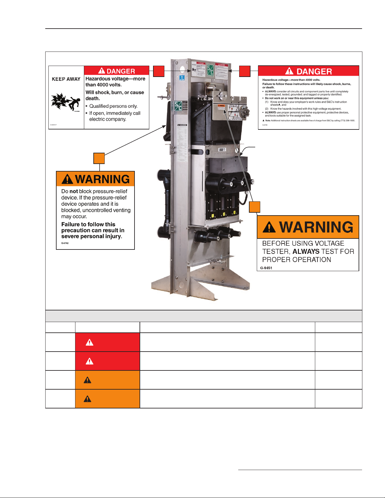
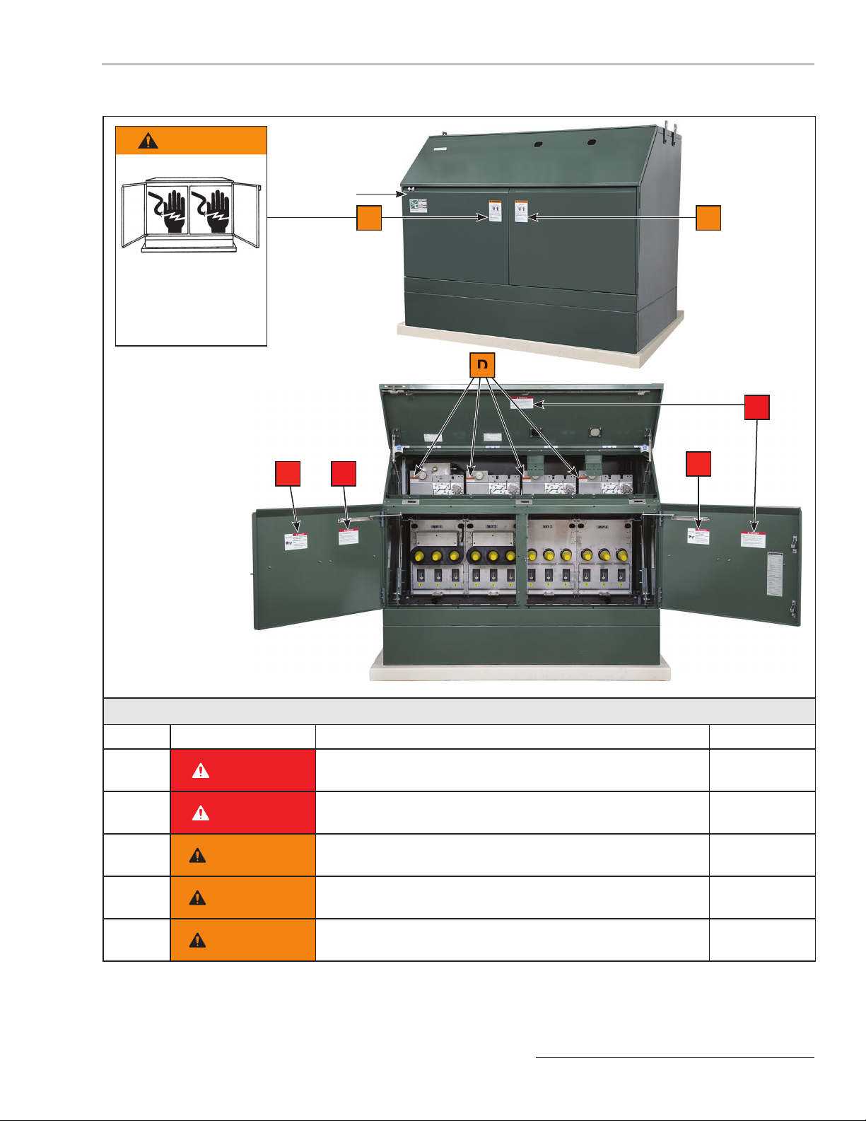
7. SAFETY LABELS. Do not remove or obscure any of
the“DANGER,”“WARNING,”“CAUTION,”or“NOTICE”
labels.
8. ENERGIZED BUSHINGS. Always assume the
bushings are energized unless proven otherwise by
test, by visual evidence of an open-circuit condition at
the load-interrupter switch or fault interrupter, or by
observing that the load-interrupter switch or fault
interrupter is grounded.
9. BACKFEED. Bushings, cables, load-interrupter
switches, and fault interrupters may be energized by
backfeed.
10. GROUNDING.
• Vista SD Switchgear must be connected to a
suitable earth ground before energizing, and at all
times when energized.
• The ground wire(s) must be bonded to the system
neutral, if present. If the system neutral is not
present, proper precautions must be taken to
ensure that the local earth ground cannot be
severed or removed.
• After the switchgear has been completely
disconnected from all sources of power and tested
for voltage, properly ground the load-interrupter
switches and fault interrupters before touching any
bushings or components to be inspected, replaced,
serviced, or repaired.
11. LOAD-INTERRUPTER SWITCH OR FAULT
INTERRUPTER POSITION.
• Always confirm the open/closed position of the
load-interrupter switch or fault interrupter by visually
observing the position of the isolating disconnect.
• Load-interrupter switch or fault interrupter may be
energized by backfeed.
• Load-interrupter switch or fault interrupter may be
energized in any position.
12. MAINTAINING PROPER CLEARANCE. Always
maintain proper clearance from energized
components.

S&C Instruction Sheet 695-505 9
Shipping and Handling
Packing
Vault-mounted style Vista SD Underground Distribution
Switchgear is shipped in a wooden crate. Pad-mounted
style Vista SD Underground Distribution Switchgear is
fastened to a wood skid. At the rst opportunity, remove
all packing materials (cardboard, paper, foam padding,
etc.) from the switchgear assembly. This will prevent the
switchgear from being damaged by rainwater absorbed by
the packing materials and will also prevent wind-induced
abrasion from loose cardboard.
Inspection
Examine the shipment for external evidence of damage as
soon after receipt as possible, preferably before removal
from the carrier’s conveyance. Check the bill of lading to
make sure all listed shipping skids, crates, and containers
are present.
If there is visible loss and/or damage:
1. Notify the delivering carrier immediately.
2. Ask for a carrier inspection.
3. Note the condition of shipment on all copies of the
delivery receipt.
4. File a claim with the carrier.
If concealed damage is discovered:
1. Notify the delivering carrier within 15 days of receipt of
shipment.
2. Ask for a carrier inspection.
3. File a claim with the carrier.
Also, notify S&C Electric Company in all instances of
loss and/or damage.

10 S&C Instruction Sheet 695-505
Shipping and Handling
Handling
WARNING
When handling Vista SD Underground Distribution
Switchgear with an overhead hoist, observe standard
lifting practices as well as the general instructions
below. Failure to follow these precautions can
result in serious personal injury or equipment
damage.
Note: Refer to the nameplate affixed to exterior of
switchgear assembly for the net weight.
STEP 1. Use 6-foot (183-cm) or longer hoist slings of
equal length to prevent damage to the gear
during lifting. 4-foot (122-cm) hoist slings are
acceptable for two-way and three-way
switchgear assemblies. See Figure 4 and
Figures 5 and 6 on page 11.
STEP 2. Arrange the hoist slings to distribute lifting
forces equally between the lifting tabs.
STEP 3. Avoid sudden starts and stops.
NOTICE
Before hoisting, remove motor operator
(if supplied) for single-way vault-mounted
style Vista SD Underground Distribution
Switchgear assemblies supplied with the
“-V3” catalog number suffix (horizontal
orientation). Failure to follow this
precaution may result in damage to the
motor operator or to the switchgear
assembly from contact with the hoist
sling.
Figure 4. Hoisting a single-way vault-mounted style Vista
SD switchgear assembly.
Horizontal orientation
(catalog number suffix
“-V3”)
Vertical orientation
(catalog number suffix “-V1”
or “-V2”)

S&C Instruction Sheet 695-505 11
Shipping and Handling
Figure 6. Hoisting a pad-mounted style Vista SD switchgear assembly (multi-way assembly shown).
Figure 5. Hoisting a multi-way vault-mounted style Vista SD switchgear assembly.

12 S&C Instruction Sheet 695-505
Installation
Vault-Mounted Style
Switchgear Placement
STEP 1. At the installation site, remove all separately
packaged components (if any) shipped with the
switchgear assembly and set them aside.
STEP 2. Remove switchgear assembly from its crate and
lift it into place, observing the precautions
given under the “Handling” section on page 10.
See Figure 7.
NOTICE
For vault-style switchgear assemblies
mounted in the horizontal orientation
(catalog number suffix “-V3”), the clearance
between the back of the bus work and the
floor of the vault is approximately ½-inch
(13 mm). Be sure the floor beneath the
switchgear assembly is clean and level.
Failure to follow this precaution may
result in damage to the switchgear from
contact with the floor or from contact
with foreign objects lying on the floor.
STEP 3. Secure the switchgear assembly in place using
½-inch fasteners (supplied by user). Figure 7. Single-way vault-mounted style switchgear assembly
shown in shipping crate. Shipping crates for multi-way
switchgear assemblies are similar.

S&C Instruction Sheet 695-505 13
Installation
Single-Way Vault-Mounted Style Unit
Installed Through 31½-Inch Manhole
STEP 1. At the installation site, remove all separately
packaged components (if any) shipped with the
switchgear assembly and set them aside.
STEP 2. Remove switchgear assembly from its crate.
STEP 3. Remove optional motor operator, if supplied
(see S&C Instruction Sheet 695-520).
STEP 4. Remove optional continuous ground bus, if
supplied, and the upper bushing or bushing-well
adapters (see S&C Instruction Sheet 695-530).
See Figure 8.
STEP 5. While the switchgear assembly is suspended by
the hoist slings, remove the mounting stand
feet.
STEP 6. Lower the switchgear assembly through the
manhole opening.
STEP 7. Re-install the mounting stand feet removed in
Step 5, and move the switchgear assembly into
place.
STEP 8. Secure the switchgear in place using ½-inch
fasteners (supplied by user).
STEP 9. Re-install the bushing or bushing-well adapters
(see S&C Instruction Sheet 695-530) and the
continuous ground bus (if furnished) removed
in Step 4.
STEP 10. Re-install the motor operator (see S&C
Instruction Sheet 695-520) removed in Step3.
Figure 8. Vault-mounted switchgear assemblies are shipped
on a skid.
Continuous
ground bus
Bushing or bushing
well adapters
Bushing or bushing
Bushing or bushing
Mounting
stand feet

14 S&C Instruction Sheet 695-505
Installation
Cables
WARNING
Before energizing the switchgear, replace the shipping
covers on all bushings and bushing wells with elbows
or insulated protective covers or caps. Failure to
replace the shipping covers on all bushings with
elbows or insulated protective covers or caps can
result in a flashover and serious personal injury
or death.
STEP 1. Remove the shipping covers from the
600-ampere bushing (yellow) or 200-ampere
bushing wells (orange). See Figure 9.
NOTICE
ALWAYS follow proper cable-installation
practices. When installing cable that will be
attached to the switchgear, provide a strain-
relief segment to minimize the load on the
bushings. Cables must be allowed to expand
and flex without putting a significant load on
the bushings. For a pit, either loop the cable
in the pit or bring it into the pit horizontally
and up to the gear at a 90° angle. Failure
to follow these precautions can result
in damage to the bushings and bushing
wells.
STEP 2. Install cable support brackets in accordance
with the appropriate reference drawing
included in the installation and operation
information kit. See Table 1.
STEP 3. Terminate the cables with user-furnished
separable insulated connectors, following the
manufacturer’s instructions.
Figure 9. Remove the shipping covers from 600-ampere
bushing—(yellow) or 200-ampere bushing wells (orange).
Ground-pad (one per way)Ground-pad (one per way)
Table 1. Reference Drawings for Cable-Support Brackets
Switchgear Style Reference Drawing
Single-way
Vertical orientation, cables enter/exit from top, operating mechanism on bottom (catalog
number suffix “-V1”) RD -7540-1
Vertical orientation, cables enter/exit from bottom, operating mechanism on top (catalog
number suffix “-V2”) RD-7540-2
Horizontal orientation, cables enter/exit from sides (catalog number suffix “-V3”) RD-7540-3
Multi-way
Vertical orientation, cables enter/exit from top, operating mechanism on bottom (catalog
number suffix “-V1”) RD-7544-3-V1
Vertical orientation, cables enter/exit from bottom, operating mechanism on top (catalog
number suffix “-V2”) RD-7544-3-V2

S&C Instruction Sheet 695-505 15
Installation
Grounding
STEP 1. Connect the ground pads on each way of the
switchgear assembly to the system ground in
accordance with the user’s standard grounding
practice. See Figure 9 on page 14.
STEP 2. If the switchgear is furnished with the
continuous ground bus (catalog number sufx
“-O”), connect the ground bus to the system
ground in accordance with the user’s standard
practice.
STEP 3. Use the equivalent of 4/0 copper (or cable sized
in accordance with the user’s standard practice)
in either a single or multiple connection to
realize the maximum momentary rating of the
switchgear assembly. For a multiple cable
connection, cables smaller than 1/0 copper or
equivalent should not be used.
STEP 4. Connect the cable concentric-neutral wires to
the grounding system as appropriate.
Fault Indicators
Fault indicators are to be furnished by the user and
installed in accordance with the manufacturer’s instruc-
tions. Optional mounting provisions for fault indicators
(catalog number sufx “-F1” or “-F2”) are available for Vista
SD Underground Distribution Switchgear. If mounting
provisions are specied, mount the fault indicators on the
mounting brackets and attach the associated sensors to
the cables below the cable terminations.

16 S&C Instruction Sheet 695-505
Installation
Pad-Mounted Style
Switchgear Placement
STEP 1. At the installation site, remove all separately
packaged components (if any) shipped within
the pad-mounted gear enclosure and set them
aside.
STEP 2. Unbolt the switchgear assembly from its
skid and lift the unit onto the mounting
pad, observing the precautions given under the
“Handling” section on page 10. See Figure 10.
Refer to the catalog dimensional drawing
furnished and verify the enclosure is positioned
correctly and the unit is properly aligned with
respect to the anchor bolts (or ush anchors).
STEP 3. Level the enclosure using metal shims (user
provided) as required between the mounting
pad and the enclosure. Then, secure the
enclosure to the pad using the anchor brackets
provided (see anchor-bolt detail on the catalog
dimensional drawing). Make sure the hinged
roof section and all doors open and the latch
closes without binding. Binding indicates
enclosure distortion that must be corrected by
additional shimming.
Access to Interior
STEP 1. Remove the shipping clamp from the padlock
recess. See Figure 11.
STEP 2. Insert a pentahead socket wrench or tool (or a
hexhead socket wrench or tool if catalog
number sufx “-H1” is specied) into the hinged
roof latching mechanism. Rotate the wrench or
tool 360° counterclockwise to unlatch the
hinged roof. See Figure12.
NOTICE
Do not apply any undue force when
attempting to open the hinged roof or a
door. The use of undue force may damage
the latching mechanism. If optional key
interlocks are provided, make certain the
interlocks are in their correct positions to
allow door opening.
Figure 12. To unlock the hinged roof, turn the pentahead
socket wrench 360° counterclockwise.
Shipping
clamp
Figure 10. Pad-mounted switchgear assemblies are shipped
on a skid.
Figure 11. Remove the shipping clamp.

S&C Instruction Sheet 695-505 17
Installation
STEP 3. Lift the hinged roof to approximately 45° above
horizontal; the “hold-open” latching mechanism
will engage automatically. See Figure 13.
WARNING
After lifting the roof open and ensuring
the “hold-open” latching mechanism is
engaged, release pressure on the hinged
roof slowly. Failure to engage the “hold-
open” latching mechanism could result
in personal injury.
STEP 4. To gain access to the termination compartment,
lift the latch handle to open the right-hand door
or the center door. See Figure 14. Open door far
enough to permit the door- holder mechanism to
engage automatically.
STEP 5. To open the left-hand door, lift the nger latch.
See Figure 15. Open door far enough to permit
the door-holder mechanism to engage
automatically.
Note: Optional pad-mounted style enclosures
furnished on switchgear assemblies with five
or six ways have three doors. The right-hand
door and the center door have lift-style latch
handles. The left-hand door has a finger latch.
Figure 13. Lift the hinged roof all the way open to engage
the “hold-open” latching mechanism.
Figure 14. To gain access to the termination compartment,
lift the latch handle to open the right-hand door.
Figure 15. To open the left-hand door, lift the finger latch.

18 S&C Instruction Sheet 695-505
Installation
Cables
STEP 1. Remove the cover panels by unscrewing the
pins connecting the panels to the front of the
enclosure. Lift the front of each panel upwards
and pull outwards to disengage the tab at the
back of the panel from the slot at the bottom of
the operating mechanism. See Figure 16.
STEP 2. When pulling cables, the hinged roof can be
placed in a second, more vertical position. While
pushing up slightly on the hinged roof, release
the latches on the “hold-open” mechanisms on
both sides of the switchgear enclosure. Lift the
hinged roof to the second, more vertical
position; the “hold-open” latching mechanism
will automatically engage. See Figure 17 on
page 19. Lifting the hinged roof to the second,
more vertical position is a two-person exercise,
especially on switchgear assemblies having
four or more ways.
NOTICE
The hinged roof cannot be placed in
the second, more vertical position if the
hinged-roof counterweights are attached.
If necessary, remove the pins connecting
the upper and lower lever arms of the
counterweight mechanism. See Figure 18
on page 20.
WARNING
Before energizing the switchgear, replace
the shipping covers on all bushings and
bushing wells with elbows or insulated
protective covers or caps. Failure to replace
the shipping covers on all bushings with
elbows or insulated protective covers
or caps can result in a flashover and
serious personal injury or death.
STEP 3. Remove the shipping covers from the
600-ampere bushings (yellow) or 200-ampere
bushing wells (orange). See Figure 20 on
page 21.
Figure 16. To remove cover panels, unscrew the pins
connecting the panel to the enclosure (a), lift up on the panel
and pull outward (b).
(a)
(b)

S&C Instruction Sheet 695-505 19
Installation
Figure 17. Release the latches on the “hold-open”
mechanisms (circled) and lift the roof to the second, more
vertical position (shown).
NOTICE
ALWAYS follow proper cable-installation
practices. When installing cable that will be
attached to the switchgear, provide a strain-
relief segment to minimize the load on the
bushings. Cables must be allowed to expand
and flex without putting a significant load on
the bushings. For a pit, either loop the cable
in the pit or bring it into the pit horizontally
and up to the gear at a 90º angle. Failure
to follow these precautions can result
in damage to the bushings and bushing
wells.
STEP 4. Install cable-support brackets in accordance
withtheappropriatereferencedrawingincluded
in the installation and operation information
kit. See Table 2.
Table 2. Reference Drawings
for Cable-Support Brackets
Switchgear Style Reference Drawing
All styles①(catalog number suffix “-P1”) RD-7568
①Cable-support brackets are not required if the switchgear assem-
bly is supplied with a pad-mounted style enclosure to be installed on a
concrete pad.
STEP 5. Terminate the cables with user-furnished
separable insulated connectors, following the
manufacturer’s instructions.

20 S&C Instruction Sheet 695-505
Installation
Attach Hinged-Roof Counterweights
STEP 1. If the roof was previously lifted to the second
most vertical position, return it to the 45°
position.Ontheright-handsideoftheswitchgear
enclosure, while pushing up on the hinged roof,
release the latch on the “hold-open” mechanism.
See Figure 23 on page 23. Allow hinged roof to
sag against the “hold-open” mechanism. At the
other end of the enclosure, push up on the
hinged roof just enough to allow the left-hand
“hold-open” mechanism latch to be released,
ensuring the right-hand “hold-open” latching
mechanism does not re-engage. Lower the
hinged roof to the 45° position.
STEP 2. To attach hinged-roof counterweights, rst
remove the shipping materials surrounding the
counterweight mechanisms on both ends of the
enclosure. See Figure 18. Then, cut the plastic
cable ties holding the longer lever arms in the
down position.
STEP 3. At one end of the enclosure, pivot the longer
lever arm up and position it on the back side of
the shorter upper lever arm (i.e., the longer lever
arm should be closest to the side wall of the
enclosure). Align the two holes in both lever
arms—it may be necessary to lift up slightly on
the longer lever arm to achieve this goal—and
press the captive pin through the holes in both
lever arms. Spring-loaded tabs in the pin will
automatically extend to engage the retaining
pin.
STEP 4. Repeat Step 3 at the opposite end of the
enclosure.
Figure 18. To attach the hinged-roof counterweights,
remove the shipping material surrounding the counterweight
mechanism (a), pivot longer lever arm up and position it on
the back side of the shorter upper lever arm (b), push the
captive pin through the holes in both lever arms(c). Spring-
loaded tabs in the pin will automatically extend to engage
the pin.
(a) (b)
(c)
This manual suits for next models
2
Table of contents
Other S&C Industrial Equipment manuals
Popular Industrial Equipment manuals by other brands

Elettrotest
Elettrotest HPS/P/200K user manual

Dover
Dover Universal 5588 Series instruction manual

schmersal
schmersal AZM300Z-ST-1P2P-A-DU Instructions for operation

Siemens
Siemens 8US1998-1CA10 operating instructions

dymax
dymax BlueWave AX-550 Quick start instructions

GESTRA
GESTRA RHOMBUSline MK 45-1 Original Installation Instructions