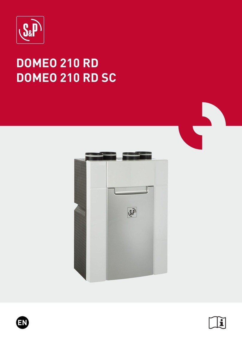
S&P COR-IND M 1000 W 27 User manual

COR-IND M 1000 W 27
COR-IND M 1500 W 35
MANUAL DE INSTALACIÓN. INSTRUCCIONES DE USO.
INSTALLATION AND OPERATION MANUAL.
NOTICE D’INSTALLATION ET D’UTILISATION.
ISTRUZIONI D’USO ED INSTALLAZIONE.
INSTRUÇÕES DE USO E MONTAGEM.
GEBRAUCHS- UND MONTAEANWEISUNGEN.
LUCHTGORDIJNEN.
INSTRUKCJE UŻYTKOWANIA I MONTAŻOWE.
HASNÁLATI ÉS SZERELÉSI UTASÍTÁSOK.
ΟΔΗΓΙΕΣ ΕΓΚΑΤΑΣΤΑΣΗΣ KAI ΛEITOYPΓIAΣ
COR-IND M 1000 W 27
COR-IND M 1500 W 35

2
ä£]ä°
ÈÎ
°°
°ä]£ä
ä£]ä°
ÈÎ
°°
ABCD
COR-IND 1000 W33M
TIPO
1076 1076220 220
Fig.1
Fig.2 (a)
2
COR-IND M 1000 W 27

3
COR-IND 1000 W50M
COR-IND M 1500 W 35

4
COR-IND M 1000 W 27 - COR-IND M 1500 W 35
Fig.5 (a)
Fig.5 (b)
CORs-INDs
N
LL
2
1
CR-20 L
2
1
MARRON
NORRAM
LUZA
LUZA
OJOR
OLLIRA
MA
OCNALB
EDREV-OLLIRAMA
MIN. 3x1mm 2
CORs-INDs
N
LL2
1
MARRON
NORRAM
LUZA
LUZ
A
OJOR
OLLIRAMA
OCNALB
EDREV-OLLIRAMA
MIN. 0,75mm2
MIN. 3x1mm 2
CR-30 4d 3 2 1a
CORs-INDs
N
L1L2L3
NORRAM
LUZA
AZUL
SIRG
ORGEN
EDREV-
OLLIRAMA
4d
3
2
1a
SIRG
OJOR
OLLIRAMA
ORGEN
EDREV
CORs-INDs
4d
3
2
1a
N
L1L2L3
NORRAM
LUZA
AZUL
SIRG
SIRG
ORGEN
OJOR
OLLIRAMA
O
RGEN
EDREV
EDREV-OLLIRAMA
MIN. 0,75mm2
MIN. 5x16 mm 2
COR-IND-M 1500/36 =
MIN. 5x10 mm 2
COR-IND-M 1000/18/24
COR-IND-M 1500/24 =
MIN. 5x16 mm 2
COR-IND-M 1500/36 =
MIN. 5x10 mm 2
COR-IND-M 1000/18/24
COR-IND-M 1500/24 =
5
COR-IND-M 1000 F - COR-IND-M 1500 F
COR-IND-M 1000/12
COR-IND-M 1500/18
Fig.5
COR-IND 1000 W33M - COR-IND 1500 W50M
CONTROL CR-20
SECUENCIA CONEXIONES
POSICIONES
CIRCUITOS
123
a1
2
CR-20
CORs-INDs
L
2
1
L2
1
N
L
Fig.4 (a)
MARRON
NORRAM
LUZA
LUZA
OJOR
OLLIRAMA
OCNALB
EDREV-OLLIRAMA
° ÎÝ£Ó
° ä]Çx Ó
4
COR-IND M 1000 W 27 - COR-IND M 1500 W 35
Fig.4

5
ESPAÑOL
INTRUCCIONES IMPORTANTES
ADVERTENCIAS DE SEGURIDAD
IMPORTANTE: ESTOS APARATOS
DEBERÁN CONECTARSE A UNA TOMA
DE TIERRA.
INSTALACIÓN
CONEXIONADO ELÉCTRICO Fig.4
Los aparatos de esta serie ofrecen la
posibilidad de actuar como cortinas de aire
frío / caliente.
Rogamos compruebe el perfecto estado y
funcionamiento del aparato al desembalarlo
ya que cualquier defecto de origen está
amparado por la garantía S&P.
El aparato no deberá estar situado
justamente debajo o encima de una toma de
corriente.
No cubrirlo con objetos o prendas que
impidan la libre circulación del aire. Si se
cubre existe el riesgo de sobrecalentamien-
to.
Mientras esté en funcionamiento, el cable de
conexión no deberá estar situado delante de
la salida del aire.
Si se instala en el cuarto de baño, deberá
colocarse de manera que los interruptores u
otros dispositivos de mando no pueden ser
tocados por una persona que esté en la
bañera o ducha.
No deben quedar objetos inflamables a
menos de 50cm. del circuito del aire caliente
(cortinas, etc.).
Mantener limpias las rejillas de entrada y
salida de aire. Siempre que se realice la
limpieza o cualquier manipulación interior,
debe tenerse la preocupación de desconec-
tar el aparato a través de los medios de
desconexión de la instalación fija.
No manipular el aparato con las manos
mojadas.
La instalación deberá ser realizada por un
técnico electricista.
Los medios de desconexión que deben ser
incorporados a la instalación fija, para su
desconexión omnipolar de la red de alimen-
tación, debe presentar una separación de
contactos de al menos 3 mm en todos los
polos.
Para el funcionamiento como cortina de aire,
la distancia máxima al suelo no deberá ser
superior a 6 metros.
La distancia mínima entre las cortinas y el
suelo debe ser de 3 metros.
La unidad deberá ser fijada a una superficie
conveniente para tal aplicación.
Deberán de respetarse las distancias
mínimas según la Fig.1.
Para instalar seguir la secuencia siguiente:
Si se utilizan las tuercas roscadas ya
colocadas en el aparato, deben marcarse
los centros de los tornillos (M-12) según la
tabla de la Fig.2(a) y Fig.2(b).
Para acceder a las fichas de conexión,
deberá de abrirse la reja frontal,
desatornillando los tornillos “A” de la Fig.3.
Seguir el proceso inverso para cerrar.
La presión máxima de trabajo del radiador
de agua no será superior a 4Kg/cm .
La temperatura máxima del agua caliente no
deberá ser superior a 95ºC.
La batería de agua no debe funcionar a
temperaturas inferiores a 5ºC. En el caso en
que la temperatura pueda descender por
debajo de este límite deberá usarse liquido
anticongelante o vaciar la instalación.
La bomba de agua debe conectarse a la
batería a través de las entradas previstas de
3/4" rosca gas.
Son aparatos de instalación fija. En su
conexionado a la red, deberán tenerse en
cuenta las directrices que se indican en el
Reglamento de Baja Tensión y las propias
de cada país.
Debe preverse en la instalación un
2
5

6
interruptor magnetotérmicouotro
dispositivo de desconexión omnipolar que
interrumpa todas las líneas de alimentación
al aparato.
Proceder al conexionado a la red, compro-
bando que la tensión de la misma coincida
con la indicada en la placa de característi-
cas.
Utilizar la sección y número de conductores
indicados en los esquemas correspondien-
tesacada modelo.
Fijar los cables con el prensaestopas.
CONEXIONADO CONTROLREMOTO.
(Dichocontrol se vendeaparte como
accesorio).
EL CONEXIONADO DE DOSOMÁS
CORTINAS DEL MISMO MODELO (MÁX.5
UNIDADES) DEBÉN HACERSE SEGÚN EL
ESQUEMADE LAFig.5.
En el caso de conexión múltiple, debe
tenerse en cuenta el aumento de sección de
los cables de alimentación en función del
número de aparatos conectados.
Estas cortinas de aire no necesitan un
especial mantenimiento, sin embargo, les
aconsejamos:
1- Mantener limpias de polvo las rejillas de
entrada y salida de aire. Límpielas en frío
con un trapo seco. (Evite usar disolventes o
detergentes abrasivos)
2- Cada año efectuar una limpieza a fondo
delinteriordelaparato. (Técnico
especialista).
3- Para cualquier tarea de mantenimiento
deberá accionarse el dispositivo de corte
omnipolar para evitar que haya partes en
tensión dentro del aparato.
La red de Servicios Oficiales S&P garantiza
unaadecuada asistencia técnica en
cualquier punto de España.
En el caso de observar alguna anomalía en
el aparato, rogamos se ponga en contacto
con cualquiera de los servicios menciona-
dos, donde serán debidamente atendidos.
Cualquiermanipulación efectuadapor
personas ajenas a los Servicios Oficiales
S&P nos obliga a cancelar su garantía.
S&P se reserva el derecho a modificaciones
del producto sin previo aviso.
PUESTAEN MARCHAY
FUNCIONAMIENTO.
NOTA:
MANTENIMIENTO
ASISTENCIATÉCNICA
6
MODELO
CORTINA MODELO CONTROL
REMOTO
CR-20
COR-IND M 1000 W 27
COR-IND M 1500 W 35
CR-20

7
ENGLISH
IMPORTANT: SAFETY GUIDELINES
IMPORTANT: THIS APPLIANCE MUST BE
EARTHED.
INSTALLATION
ELECTRICAL CONNECTION Fig. 4
The models in this range offer the possibility
of working as hot/cold air curtains.
We advise you to check that the unit is in
perfect condition when unpacking it, as any
manufacturing or quality defect is covered by
the S&P guarantee.
The appliance must not be right above or
below a socket.
Do not cover the unit with clothes or objects
that may obstruct the airflow and cause
overheating.
While in operation, the connection cable
must not be in front of the air outlet.
If it is installed in the bathroom, it must be
placed so that the switches or other control
devices cannot be touched by anyone in the
bathtub or shower.
There must not be any inflammable objects
at less than 50 cm from the unit (such as
window curtains, etc.).
Keep the inlet and outlet grilles clean. When
cleaning them, disconnect the unit from the
mains supply.
Do not manipulate the unit with wet hands.
The installation work must be carried out by
an electrician.
The means of disconnection from the mains
supply must have an opening distance of at
least 3 mm in all poles.
To operate the unit as an Air Curtain, the
maximum distance to the floor must not be
greater than 6 metres.
The minimum distance between the Air
Curtain and the floor must be 3 metres.
The unit must be fixed to a convenient
surface.
The minimum distances shown in Fig. 1
must be kept.
To install the unit, proceed as follows:
If the spiral nuts already placed in the device
are used, the centres of the screws (M-12)
must be marked according to the table in Fig.
2 (a) and Fig. 2(b).
To access the connection cards you must
open the front grille by unscrewing the
screws marked “A” in Fig. 3. To close, follow
the process in reverse order.
The maximum working pressure of the water
radiator must not exceed 4 Kg/cm .
The maximum temperature of the hot water
must not exceed 95ºC.
The water coil must not operate at
temperatures of less than 5ºC. When there is
a risk of the temperature dropping below this
limit antifreeze liquid must be used or the
installation must be emptied.
The water pump must be connected to the
coil via the 3/4" gas thread inlets fitted for this
purpose.
They are installed appliances. When
connecting them to the mains, the standards
and regulations in force in your country must
be strictly adhered to.
Within the installation an electrical isolation
switch must be present, to enable the
installer to cut all supply lines.
Connect the unit to the mains supply,
checking that the voltage and frequency are
the same as those indicated on the electrical
rating plate.
Use the cables with the number of wires and
sections as indicated on the wiring diagram
for every model.
Fix the cables with the clamp provided.
2
7

8
OPERATION
NOTE:
MAINTENANCE
AFTER SALES SERVICE
REMOTE CONTROLCONNECTION.
(This control is sold separately as an
accessory).
IF CONNECTING BETWEEN TWO OR
MORE AIR CURTAINS OF THE SAME
MODEL (MAX.5UNITS), PLEASE REFER
TO WIRING DIAGRAM IN Fig. 5.
In the case of multiple connection, the
Installermust consider the increased
number of feeders based on the number of
connected units.
These air curtains do not need any special
maintenance,however the following is
recommended:
1- Keep the inlet and outlet grilles clean.
Clean them withadry cloth (avoid using
solvents or abrasive detergents)
2- Onceayear, the inside parts should be
cleaned by a qualified electrician.
3- In order to carry out any maintenance
tasks, the omnipolar cut-off device must be
activated to ensure that none of the parts
inside the apparatus are live.
In the event of any problems with the unit,
it is advised to contact your S&P dealer.
Any manipulation of the appliance by
personnel not appointed by S&P will cancel
the guarantee.
S&P reserves the right to modify the
product without prior notice.
8
CURTAIN
MODEL REMOTE CONTROL
MODEL
CR-20
CR-20
COR-IND M 1000 W 27
COR-IND M 1500 W 35

9

10
COR-IND M 1000 W 27
COR-IND M 1500 W 35

11
ITALIANO
ISTRUZIONI IMPORTANTI
AVVERTENZE PER LASICUREZZA
IMPORTANTE: QUESTI APPARECCHI
DEVONO ESSERE COLLEGATI AD UNA
PRESACON MESSAATERRA.
INSTALLAZIONE
COLLEGAMENTO ELETTRICO Fig. 4
Gli apparecchi di questa serie offrono la
possibilità di funzionare come barriere d'aria
fredda / calda.
Al ricevimento del materiale verificare il
perfetto stato del prodotto ed il suo
funzionamento. Eventuali difetti di costruzione
sono coperti dalla garanzia S&P.
L'apparecchio non può essere installato sotto
o sopra una presa di corrente.
Non coprire l'apparecchio con oggetti o tende
che impediscono la libera circolazione
dell'aria. In caso contrario esiste il pericolo di
surriscaldamento.
Il cavo di alimentazione non dovrà essere
posto davanti all'uscita dell'aria.
La barriera d'aria installata in un locale
destinato a bagno, dovrà essere montata in
modo che gli interruttori o altri dispositivi del
comando elettrico, siano fuori dalla portata
delle persone che utilizzano la vasca da bagno
e la doccia.
Non porre oggetti infiammabili ad una distanza
inferiore di 50 cm dal flusso dell'aria calda
(tende, ecc.).
Mantenere sempre pulite le griglie di entrata
ed uscita dell'aria. Quando si puliscono le
griglie, avere l'avvertenza di scollegare
l'apparecchio mediante il disgiuntore
dell'impianto fisso.
Non toccare l'apparecchio con le mani
bagnate.
L'installazione deve essere effettuata da
personale professionalmente competente e
autorizzato.
I dispositivi di disinserimento da inserire
nell'impianto fisso per il disinserimento
omnipolare della rete di alimentazione devono
presentare una separazione di almeno 3 mm
tra i contatti in tutti i poli.
Per il funzionamento come barriera d'aria,
l'apparecchio deve essere posto ad una
distanza massima dal pavimento non
superiore a 6 metri.
La distanza minima dal pavimento non deve
essere inferiore a 3 metri.
L'apparecchio dovrà essere fissato su una
superficie adatta per questa applicazione.
Dovranno essere rispettate le distanze
minime indicate in Fig. 1.
Per l'installazione seguire la sequenza sotto
indicata:
Se si utilizzano i tasselli inclusi con
l'apparecchio, si devono contrassegnare le
forature delle viti (M-12) con la dima Fig. 2(a) e
Fig. 2(b).
Per accedere ai collegamenti elettrici , aprire
la griglia frontale allentando le viti “A” della Fig.
3. Seguire il processo inverso per richiudere il
frontale.
La pressione massima di lavoro del radiatore
ad acqua non deve essere superiore a 4
Kg/cm .
La temperatura massima dell'acqua calda non
deve essere superiore a 95º C.
Il radiatore ad acqua non deve funzionare a
temperature inferiori a 5º C. Se la temperatura
può scendere al di sotto di questo limite,
occorre usare liquido anticongelante o
svuotare l'impianto.
Questi apparecchi sono progettati per
installazione fissa. Il collegamento alla rete
elettrica dovrà tener conto delle direttive
indicate dal regolamento di bassa tensione e
quelle del proprio paese.
L'installazione deve prevedere un interruttore
magnetotermico o altro dispositivo di stacco
multipolare che interrompa tutte le linee di
alimentazione dell'apparecchio.
Procedere al collegamento con la rete
elettrica, verificando che la tensione sia la
stessa indicata nella targhetta
2
La pompa dell'acqua deve essere collegata alla
batteria tramite le apposite entrate filettate da 3/4" .
11

12
COR-IND M 1000 W 27
COR-IND M 1500 W 35

13
PORTUGUÊS
INSTRUÇÕES IMPORTANTES
AVISOS DE SEGURANÇA
IMPORTANTE: ESTES APARELHOS
DEVEM SER LIGADOS A UMA TOMADA
DE TERRA
INSTALAÇÃO
)
LIGAÇÃO ELÉCTRICAFig.4
Os aparelhos desta série oferecem a
possibilidade de actuar como cortinas de ar
frio / quente.
Pedimos que verifiquem o perfeito estado e
funcionamento do aparelho ao desembalá-
lo, pois qualquer eventual defeito de origem
está coberto pela garantia S&P.
O aparelho não deverá estar situado por
cima nem por baixo da tomada de corrente.
Não deve ser coberto com objectos ou
peças que impeçam a livre circulação do ar.
Se o cobrir, fica sujeito a risco de sobre-
aquecimento.
Enquanto estiver em funcionamento, o cabo
de ligação não deve ficar situado diante da
saída do ar.
Se for instalado na casa de banho, deverá
colocar-se de forma a que os interruptores
ou outros dispositivos de comando não
possam ser manuseados pela pessoa que
está na banheira ou no chuveiro.
Não devem ficar objectos inflamáveis a
menos de 50cm do circuito de ar quente
(cortinas, etc.)
Manter limpas as grelhas de entrada e saída
do ar. Sempre que se realize a limpeza ou
qualquer intervenção interior, deve ter-se o
cuidado de desligar o aparelho a través dos
meios de desconexão da instalação fixa.
Não manipular o aparelho com as mãos
molhadas.
A instalação deverá ser realizada por um
técnico electricista.
Os meios de desligamento que devem ser
incorporados na instalação fixa, para a sua
desconexão omnipolar da rede de
alimentação, devem ter uma separação de
contactos de pelo menos 3mm, em todos os
pólos.
Para o funcionamento como cortina de ar, a
distância máxima ao solo não deverá ser
superior a 6 metros.
A distância mínima entre a cortina e o solo
deve ser de 3 metros.
A unidade deverá ser fixada a uma
superfície adequada para tal aplicação.
Devem ser respeitadas as distâncias
mínimas, segundo Fig.1.
Para instalar, seguir a sequência seguinte
Se utilizar as porcas roscadas já colocadas
no aparelho, deve-se marcar o centro dos
parafusos (M-12) segundo a tabela da Fig.2
(a) e Fig.2 (b
Para ter acesso às fichas de ligação
deverá abrir a grelha frontal,
desaparafusando os parafusos “A” da Fig.
3. fazer o processo inverso para fechar
A pressão máxima de trabalho do radiador
de água não será superior a 4Kg/cm .
A temperatura máxima da água quente não
deverá ser superior a 95ºC.
A bateria de água não deve funcionar a
temperaturas inferiores a 5ºC. No caso em
que a temperatura possa descer abaixo
deste limite, deverá ser usado liquido
anticongelante ou esvaziar a instalação.
A bomba de água deve ligar-se à bateria
através das entradas previstas de 3/4" rosca
gás.
São aparelhos de instalação fixa. Na sua
ligação à rede, deve ter-se em conta as
directrizes que estão indicadas no
Regulamento de Baixa Tensão, em
:
.
2
13

14
conformidade das normas de cada país.
Deve prever-se na instalação um interruptor
magnetotérmico ou outro dispositivo de
corte omnipolar que interrompa todas as
linhas de alimentação ao aparelho.
Proceder à ligação da rede, verificando se a
tensão éamesma que a indicada na placa
de características.
Utilizar a secção e número de condutores
indicados no esquema correspondente a
cada modelo.
Fixar os cabos comoprensa-estopas.
LIGAÇÃO CONTROLO REMOTO (o
controlo vende-se separadamente como
acessório)
ALIGAÇÃO DE DUAS OU MAIS
CORTINAS DO MESMO MODELO (MÁX.5
UNIDADES) DEVE FAZER-SE SEGUNDO
O ESQUEMADAFig.5.
No caso de ligação múltipla, deve ter em
contaoaumento de secção dos cabos de
alimentação em função do número de
aparelhos ligados.
Estas cortinas de ar não necessitam de uma
manutenção especial. No entanto,
aconselhamos:
1- Manter limpas de pó as grelhas de
entrada e saída do ar. Limpe em frio com um
pano seco (evite usarsolventes ou
detergentes abrasivos)
2- Cada ano efectuar uma limpeza a fundo
no interiordoaparelho (Técnico
especialista)
3- Para qualquer tarefa de manutenção
deverá accionar o dispositivo de corte
omnipolar para evitar que haja partes em
tensão dentro do aparelho.
Em caso de qualquer anomalia, pedimos o
favor que contacteoseu fornecedor, pois a
Assistência Técnica S&P garante-lhe um
bom atendimento.
Qualquer manipulação efectuada por
pessoas alheias aos Serviços S&P, obriga-
nosacancelar a sua garantia.
S&P reserva-se no direito a modificações do
produto sem prévio aviso.ARRANQUE E FUNCIONAMENTO.
NOTA:
MANUTENÇÃO
ASSISTÊNCIA TÉCNICA
14
MODELO
CORTINA
MODELO
CONTROLO
REMOTO
CR-20
CR-20
COR-IND M 1000 W 27
COR-IND M 1500 W 35

15
DEUTSCH
WICHTIGE HINWEISE
SICHERHEITSHINWEISE
MONTAGE
ELEKTRISCHER ANSCHLUSS Abb.4
Die Geräte dieser Serie ermöglichen den
Einsatz sowohl als Kalt-, als auch als
Warmluftschleier.
Bitte prüfen Sie das Gerät nach der
Entnahme aus der Verpackung auf
einwandfreien Zustand und Funktion.
Eventuelle Herstellungsfehler fallen unter
die S&P-Garantie.
Das Gerät darf nicht unmittelbar unterhalb
oder oberhalb einer Stromsteckdose
installiert werden.
Um einen unbehinderte Luftumwälzung zu
gewährleisten, dürfen keine Gegenstände
oder Kleidungsstücke über das Gerät gelegt
werden. Andernfalls besteht die Gefahr
einer Überhitzung des Geräts.
Das Kabel soll nicht vor den Luftaustritt
gelegt werden, solange das Gerät in Betrieb
ist.
Wird der Türluftschleier in einem
Badezimmer installiert, so ist dieser so
anzubringen, daß die Schalter und
Bedienelemente nicht von der Badewanne
oder von der Dusche aus erreichbar sind.
Es In unmittelbarer Nähe des Heißluftstroms
(ca. 50 cm) dürfen sich keine entflammbaren
Gegenstände befinden (Vorhänge und
dergl.).
Die Luftgitter am Eintritt und Austritt des
Gerätes sind sauber zu halten. Vor dem
Reinigen des Geräts ist dieses ausser
Betrieb zu setzen (Schalter an der festen
elektrischen Installation).
Das Gerät nicht mit nassen oder feuchten
Händen berühren.
Die Installierung muß von einem Elektriker
durchgeführt werden.
ACHTUNG: DAS STROMNETZ, AN DAS
DAS GERÄT ANGESCHLOSSEN WIRD,
MUSS GEERDET SEIN.
Bei der festen elektrischen Installation ist ein
Trennschalter mit einer Trennstrecke von
mind. 3 mm pro Pol vorzusehen (allpoliger
Schutz.
Damit das Gerät seine Aufgabe als
Türluftschleier einwandfrei erfüllt, ist es in
einemAbstand von höchsten 6 Metern zum
Boden zu installieren.
Der minimale Abstand zwischen dem Gerät
und dem Boden beträgt 3 Meter.
Die Einheit ist an einer dem Zweck
entsprechenden Oberfläche anzubringen.
Die Mindestabstände gemäß Abb. 1 sind
einzuhalten.
Bei der Montage des Geräts ist wie folgt
vorzugehen:
Werden die mit dem Gerät mitgelieferten
Gewindemuttern benutzt, so sind die
Bohrlöcher für die Schrauben (M-12) gemäß
der Tabelle in Abb. 2(a) und Abb. 2(b)
anzubringen.
Um auf die Anschlußklemmen zuzugreifen,
muß das Frontgitter geöffnet werden. Hierzu
die Schrauben „A“, Abb. 3, abschrauben.
Zum Schließen ist in umgekehrter
Reihenfolge vorzugehen.
Der maximale Betriebsdruck des
Warmwasser-Heizkörpers darf nicht den
Wert von 4K g/cm übersteigen.
Die Höchsttemperatur des Wassers darf
nicht über 95ºC liegen.
Die Wasserbatterie darf nicht bei
Temperaturen unter 5 ºC betrieben werden.
Sollte die Temperatur unter diesen
Grenzwert fallen, ist entweder ein
Frostschutzmittel zu verwenden oder muss
die Installation entleert werden..
Die Wasserpumpe ist an die Batterie über
die vorgesehenen 3/4" Schraubanschlüsse
anzuschliessen.
Bei den Türluftschleiern handelt es sich um
2
15

16
COR-IND M 1000 W 27
COR-IND M 1500 W 35

17
NEDERLANDS
BELANGRIJKE INSTRUCTIES
VEILIGHEIDSWAARSCHUWINGEN
BELANGRIJK: DEZE APPARATEN
MOETEN WORDEN GEAARD.
INSTALLATIE
ELEKTRISCHEAANSLUITING
INBEDRIJFSTELLING EN
BEDIENING
De luchtgordijnen uit deze serie kunnen zowel
als voor warme als koude lucht worden
gebruikt.
Wij raden u aan om te controleren of de unit in
goede staat is als u het uitgepakt heeft
aangezien elke fabricage- of kwaliteitsfout
onder de S&P garantie valt.
Hang het luchtgordijn niet recht onder of
boven een stopcontact.
Dek de in- en uitstroomopeningen van het
luchtgordijn niet af met voorwerpen of kleding
die de vrije luchtcirculatie zouden hinderen.
Het afdekken kan tot oververhitting leiden.
Als het luchtgordijn is aangesloten, mag het
snoer niet voor de luchtuitlaat zitten.
Er mogen zich geen lichtontvlambare
voorwerpen op minder dan 50 cm van de unit
bevinden (bijv. gordijnen e.d.)
Houdt de inlaat- en uitlaatroosters schoon.
Koppel de unit los van het elektrisch net
voordat u deze gaat schoonmaken of voordat
u om het even welke handeling binnen in het
apparaat gaat uitvoeren.
Raak de unit niet met natte handen aan.
De installatie dient volgens de plaatselijk
geldende regels te geschieden.
Bij de schakelaar die de verbinding vormt met
het elektrisch net moeten de contacten van
alle polen ten minste 3 mm van elkaar
gescheiden zijn in uitgeschakelde toestand.
Om het luchtgordijn goed te laten werken dient
de maximum afstand tot de vloer niet meer
dan 6 meter te bedragen.
De minimum afstand tussen het luchtgordijn
en de vloer dient 3 meter te zijn.
De unit moet op een geschikt oppervlak
bevestigd worden waarbij de minimum
afstanden, die op afbeelding 1 getoond
worden, aangehouden moeten worden.
Ga bij het installeren van de unit als volgt te
werk:
Als de spiraalmoeren gebruikt worden die al in
het apparaat zitten, dan dient het hart tussen
de centers van de schroeven (M-12) volgens
de tabel van afb. 2 (a) en afb. 2 (b) gemarkeerd
te worden.
Om de aansluitklemmen te kunnen bereiken
moet u het rooster aan de voorzijde openen
door de schroeven, weergegeven met “A” in
de Afb. 3, los te schroeven. Voer het proces uit
in de omgekeerde volgorde om het rooster te
sluiten.
De maximale werkdruk van de waterradiator
mag niet hoger zijn dan 4Kg/cm .
De maximale temperatuur van het warm water
mag niet hoger zijn dan 95ºC.
De waterbatterij mag niet functioneren bij
temperaturen onder de 5ºC. Indien de
temperatuur kan zakken onder deze limiet
moet er antivriesoplossing worden
toegevoegd of moet de installatie worden
leeggemaakt.
De waterpomp moet aan de batterij worden
gekoppeld via de voorziene ingangen met 3/4"
gasdraad.
Deze units vormen een vaste installatie. Het
luchtgordijn dient volgens de plaatselijk
geldende normen aangesloten te worden.
Er moet op de installatie een automatische
zekering of ander type omnipolaire schakelaar
worden voorzien die alle voedingsdraden van
de unit kan onderbreken.
Sluit de unit op de netvoeding aan en
controleer of het voltage en de frequentie
overeenkomen met de gegevens die op het
typeplaatje vermeld staan.
Gebruik voor elk model de juiste bedrading en
secties zoals is aangegeven op het
aansluitschema van elk model.
Bevestig de kabels met de afdichting.
AANSLUITING METAFSTANDBEDIENING.
(De afstandsbediening wordt afzonderlijk
2
Afb. 4
17

18
verkocht als accessoire ).
INDIEN ER SPRAKE IS VAN AANSLUITING
VAN TWEE OF MEER LUCHTGORDIJNEN
VAN HETZELFDE MODEL (MAX.5UNITS),
RAADPLEEG D A N H E T
AANSLUITSCHEMAVANAfb. 5.
In geval van een meervoudige aansluiting
dient de installateur rekening te houden met
extra voedingskabels, hetgeen afhankelijk is
van het aantal aangesloten units.
COR luchtgordijnen hebben geen speciaal
onderhoud nodig, maar het is raadzaam om:
1- de inlaat- en uitlaatroosters schoon te
houden. Reinig ze met een droge doek.
(gebruikGEENoplosmiddelen o f
schuurmiddelen)
2- één keer per jaar de onderdelen in het
apparaat te laten schoonmaken met behulp
van perslucht of een stofzuiger door een
erkend onderhoudspersoneel.
Haal altijd eerst de elektrische verbinding los
voordatuhiermee begint om te voorkomen dat
er onderdelen onder spanning zouden zijn.
In geval van problemen met de unit kunt u
het beste contact opnemen met uw S&P
dealer. Als er handelingen aan de unit
uitgevoerd zijn door personen die hiertoe
niet gerechtigd zijn, vervalt de S&P garantie.
S&P behoudt zich het recht voor wijzigingen
aan het product aan te brengen zonder
mededeling vooraf.
OPMERKING:
ONDERHOUD
Service
18
MODEL
GORDIJN
CR-20
CR-20
MODEL
AFSTANDSBEDIENING
COR-IND M 1000 W 27
COR-IND M 1500 W 35

19
%%"
$%73
?0A0CH I C49 B4A88 <>6s 3I80r0t 90:> :DACH=H
?>F84CAI0 27r>3=46> 284?r46>
%A>B8<H > B?A0F3I4=84 BC0=D 0?0A0CD ?>
946> A>I?0:>F0=8D ,BI4;:84 F03H
?A>3D:2H9=4 8 90:>u28>F4 >19vC4 Bs
6F0A0=29s (%
4 ?>F8=84= I=093>F0t B8v CDw ?>3
;D1 CDw =03 <849B24< ?>3rs2I4=80 3> B8428
#84 ?AIH:AHF0t DAIs3I4=80 ?AI43<8>C0<8
;D1 2Ivu280<8 >3I84wH :CgA4
D=84<>w;8F80rH1H BF>1>3=4 :Asw4=84
?>F84CAI0 , A0I84 ?AIH:AH280 8BC=8494
AHIH:> ?AI46AI0=80
=>F0=80 0?0A0CD :014;
?AIHrs2I>FH =84 <>w4 I=093>F0t B8v ?AI43
FH;>C4< ?>F84CAI0
4w4;8 DAIs3I4=84 8=BC0;>F0=4 94BC F
r0I84=24 =0;4wH D<84u28t 94 F C0:8 B?>Bg1
01H FHrs2I=8:8 ;D1 8==4 ?AI4rs2I=8:8 =84 1HrH
F I0B8v6D Av:8 >B>1H :s?8s249 B8v F F0==84
;D1 18>As249 ?AHBI=82
#84 ?>F8==> 1Ht r0CF>?0;=H27 ?AI43<8>CgF
F >3;46r>u28 <=849BI49 =8w 2< >3 >1F>3D
6>As246> ?>F84CAI0 I0Br>=H 8C3
*CAIH<HF0t F 2IHBC>u28 :A0C:8 F;>CD 8 FH;>CD
?>F84CAI0 >:>=D9s2 2IHBI2I4=80 =0;4wH
I0FBI4 ?0<8vC0t > I027>F0=8D >BCA>w=>u28
8 >3rs2I4=8D 0?0A0CD >3 I0B8;0=80
#84 <0=8?D;>F0t ?AIH 0?0A0284 <>:AH<8
Av:0<8
=BC0;0290 ?>F8==0 I>BC0t FH:>=0=0 ?AI4I
FH:F0;858:>F0=46> C427=8:0 4;4:CAH:0
,Hrs2I=8:8 :CgA4 <DBIs 1Ht DFI6;v3=8>=4
F 8=BC0;0298 BC0r49 D<>w;8F809s24 20r:>F8C4
FHrs2I4=84 0?0A0CD I B8428 I0B8;0=80 <DBIs
<84t 2> =09<=849 <8;8<4CA>FH >3BCv?
<8v3IH BCH:0<8 =0 FBIHBC:827 1846D=027
1H 0?0A0C <g6r 5D=:29>=>F0t 90:> :DACH=0
?>F84CAI=0 <0:BH<0;=0 >3;46r>ut >3
?>3r>68 =84 ?>F8==0 ?AI4:A02I0t <4CAgF
"8=8<0;=0 >3;46r>ut <8v3IH :DACH=0<8 8
?>3r>6s ?>F8==0 FH=>B8t <4CAgF
*AIs3I4=84 ?>F8==> I>BC0t ?AIH<>2>F0=4
3> ?>F84AI27=8 =0309s249 B8v 3> C46> 24;D
#0;4wH I027>F0t <8=8<0;=4 >3;46r>u28
%>32I0B 8=BC0;>F0=80 =0;4wH I027>FHF0t
=0BCv?D9s2s :>;49=>ut
4w4;8 DAIs3I4=84 94BC <>=C>F0=4 ?AIH
?><>2H I0<>2>F0=H27 =0:AvC4: uAD1H "
<DBIs 1Ht A>I<84BI2I>=4 I6>3=84 I
FH<80A0<8 =0 AHB 0 8 AHB 1
1H 3>BC0t B8v 3> :0AC ?>rs2I4=8>FH27
=0;4wH >CF>AIHt :A0Cv ?AI43=8s >3:Av209s2
uAD1H op F6 AHB , 24;D I0<:=8v280
?>BCv?>F0t F >3FA>C=49 :>;49=>u28
"0:BH<0;=4 28u=84=84 A>1>2I4 F 6AI49=8:D
F>3H =84 ?>F8==> ?AI4:A02I0t 62<
"0:BH<0;=0 C4<?4A0CDA0 6>As249 F>3H =84
?>F8==0 ?AI4:A02I0t
0C4A80 =84 ?>F8==0 5D=:29>=>F0t F
C4<?4A0CDAI4 ?>=8w49
w49 C49 6A0=82H
=0;4wH I0BC>B>F0t ?rH= I0?>184609s2H
I0<0AI0=8D ;D1 >?Agw=8t 8=BC0;029v
%><?0 F>3=0 ?>F8==0 1Ht ?>3rs2I>=0 3>
10C4A88 ?>?AI4I Irs2I:8 F:AvC=4
DACH=H Bs DAIs3I4=80<8 8=BC0;>F0=H<8 =0
BC0r4 =BC0;0290 ?>F8==0 I>BC0t FH:>=0=0
I6>3=84 I >3?>F843=8<8 FHCH2I=H<8
3>CH2Is2H<8 =8B:846> =0?8v280 8
>3?>F843=8<8 A46D;0290<8 ?A0F=H<8
>1>F8sID9s2H<8 F :0w3H< :A09D
, 8=BC0;0298 =0;4wH ?AI4F83I84t ?AI4rs2I=8:
<06=4CH2I=>C4A<82I=H ;D1 8==4
F84;>1846D=>F4 DAIs3I4=84 20r:>F8284
>328=09s24 3>?rHF ?As3D
"T "
?0A0C =8
%>32I0B 5D=:29>
I6>3=84 I AHB
K
K , ?AIH?03:D
B?03:D C4<?4A0CDAH ?>=8
" % $
% %
%U%
F
6
3

20
COR-IND M 1000 W 27
COR-IND M 1500 W 35
This manual suits for next models
1
Table of contents
Languages:
Other S&P Fan manuals
Popular Fan manuals by other brands

KING
KING WFO-24 Instruction manual and owner's guide

Prem-I-Air Elite
Prem-I-Air Elite EH0525 manual

Bestron
Bestron DFT35WB instruction manual

HAEGER
HAEGER SF-16W.006A User instructions

MALTEC
MALTEC WK500Wt-lON instruction manual

Home Decorators Collection
Home Decorators Collection 51608 Use and care guide

Weinmann
Weinmann MEDUMAT Transport quick start guide

Armstrong
Armstrong 21AR Installation and Maintenance

KUL
KUL KU33006 user manual

LUCCI Air
LUCCI Air AIRFUSION MARINER manual

Monte Carlo Fan Company
Monte Carlo Fan Company 3MTR38TMO-L Operation & maintenance manual

AirArtDeco
AirArtDeco AADQ-401 instruction manual