WARNING:This product contains a magnet. If an implanted medical device such as a pacemaker or implantable cardioverter defibrillator (ICD) is in use, magnetic fields may aect the operation of
those devices, resulting in serious injury or death. If you have an implanted medical device, keep at least 13 cm (5in.) between your device and the magnet. Please consult with your physician or medical
professional prior to using this product.
SANUS
MAGNETIC STUD FINDER
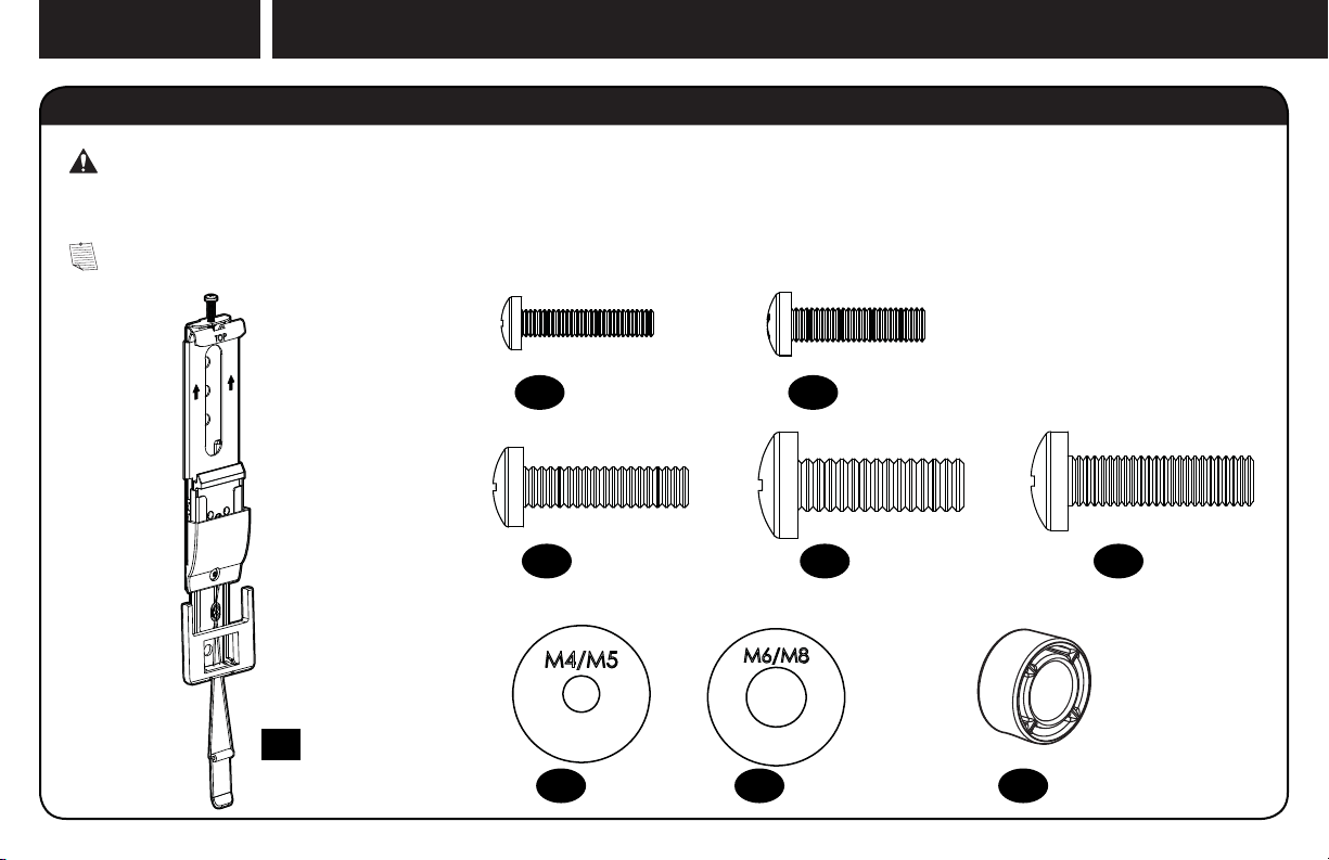
Designed to find your studs and make life easier– included in hardware kit.
TWO SIMPLE STEPS
TO FINDING YOUR STUDS:
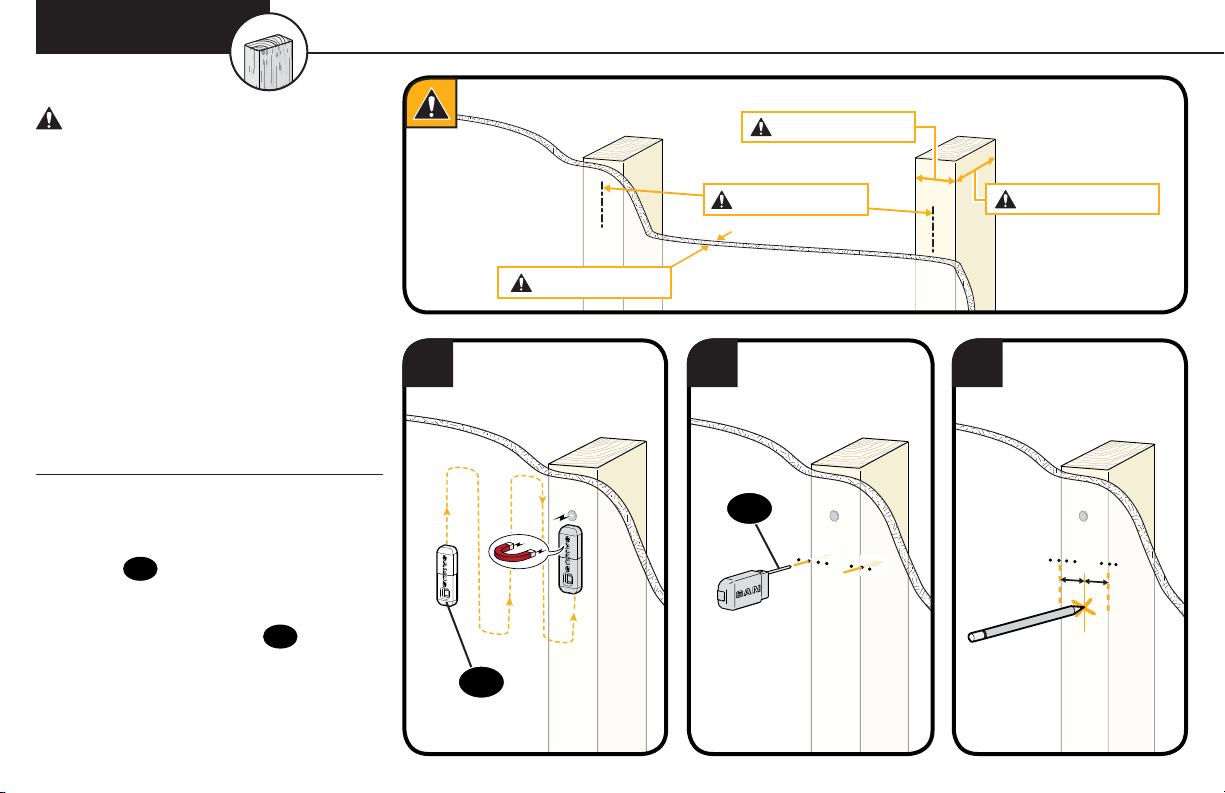
Holding it vertically, lightly move the SANUS
Magnetic Stud Finder up and down while
sliding across your wall. The magnet within
will be attracted to the screws in the stud.
Once the magnet has landed on a screw,
place a pencil mark on the wall
directly below the magnet.
You can verify this is a stud by moving the
Magnetic Stud Finder up or down to find
a second or third screw within the wall.
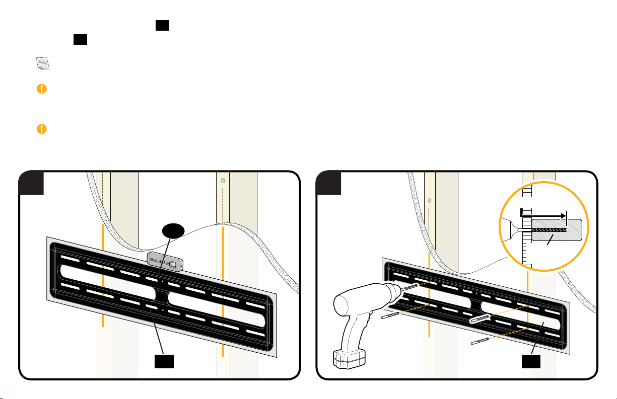
Pull apart the SANUS Magnetic Stud Finder to
expose the probing pin within. Starting about
1/2inch away from the first pencil mark insert
the probing pin into the wall every 1/8inch until
it inserts completely into the wall. Once that
happens, you know you've found one edge of
your stud. Repeat this process till you have
found the stud edges and center of the stud.
Step 1 Step 2
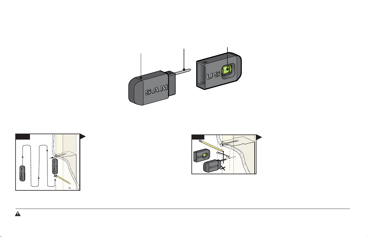
magnet
locates screws in drywall
to show exactly where
your studs are
probing pin
helps find the edges of
your stud within the wall
level
attaches to your wall plate
for hands free leveling