Sanuvox SRMax User manual

SRMax Installation Manual
WARNING
READ AND FOLLOW ALL INSTRUCTIONS CONTAINED IN THIS MANUAL BEFORE USE.
FAILURE TO COMPLY WITH THESE INSTRUCTIONS MAY RESULT IN PERSONAL
INJURIES OR DAMAGED UNIT.
Installation and servicing of equipment can be hazardous. Only trained and qualied service personnel
should install, repair or service equipment. Follow national and local safety codes.
Always wear safety glasses and work gloves for protection.
SANUVOX TECHNOLOGIES INC. | 146, rue Barr, St-Laurent, Quebec, Canada H4T 1Y4
1-888-SANUVOX www.sanuvox.com

2
About the SRMax ............................................................... 2
Important Safety Instructions & Warranty..................... 3
Included in the Box............................................................ 4
Available Options ............................................................... 4
Installation Precautions..................................................... 5
Step by Step Installation .................................................... 6
Information from the Status LED .................................... 7
Reset the lamp timer.......................................................... 8
e SRMax is specically designed to destroy biological and chemical contaminants* such as mold, bacteria, viruses,
chemicals, VOCS* and odors* that may be circulated through the HVAC system of your home.
e SRMax is installed in the RETURN (preferred) or SUPPLY plenum of our HVAC system treating the air passing
through the reecting chamber. e actual percentage of destruction obtained is based on percentage of fresh air,
air velocity, the number of passes and specic contaminants to be treated.
For information or recommendations to size appropriately your specic application, please call Sanuvox at 1-888-SANUVOX.
*Only with LMPRGXJ65 UV lamp
Table of Contents
About the SRMax
GENERAL
Installation and servicing of air-conditioning and related equipment can be hazardous due to system pressure
and electrical components. Only trained and accredited service personnel should install, repair or service such
equipment.
Untrained personnel can perform basic maintenance functions such as replacing lamps. All other operations should
be performed by trained service personnel. When working on the SRMax, observe precautions in the literature, tags,
labels attached to the unit and any other safety precautions considered as best practices in the HVAC industry.
For optimal air purication performance, the lamp and reecting chamber should be kept free of dust / residue
deposit and cleaned regularly using mild soaps or alcohol. Always spot test the cleaner to make sure it does not
damage the surface.
Under no circumstances should water be sprayed or splashed onto the SRMax.
SAFETY PRECAUTIONS
CLEANING PRECAUTIONS

3
WARNING
Before installing or performing maintenance on the unit, TURN OFF and disconnect unit from power source.
Electrical shock may cause personal injuries or possibly death.
Never expose eyes or skin to ultraviolet light from any source. e UV purier MUST be DISCONNECTED
from power source before performing maintenance of service. Personal injury may result.
Do not touch lamp glass without gloves. Reduced performance of lamp may result. Clean lamp aer handling.
e UV lamp contains a small quantity of mercury. If a lamp breaks, clean and dispose of with care.
Use only specied replacement lamps with your unit. Use of an incorrect lamp can result in damage
to the unit and/or lamp and will also void the warranty.
When applicable local regulations comprises more restrictive installation and/or certication requirements,
the aforementioned requirements prevail on those of this document and the installer agrees to conform to these
at his own expense.
When performing installation, servicing or cleaning the UV purier, it is recommended to wear safety glasses
and gloves.
IMPORTANT SAFETY INSTRUCTIONS
NOTICE
UV lamp can be disposed / recycled aer use as any other uorescent lamp.
Contact and follow your local and national authorities’ specic instructions.
Component Warranty
UV lamp 3 years
Ballast 3 years
Electronics (circuit board) 3 years
WARRANTY
e warranty applicable to the dierent components included in your purchase are as per the table below:
Make sure to keep a copy of your proof of purchase in order for the warranty to be valid.

4
Component Qty
SRMax 1
UV lamp LMPRGXJ65 1
Installation Kit 1
- UV Caution Decal
- Maintenance Decal
- Pair of cotton gloves
- Metal screws for cover (Qty:4)
- Phillips screws for frame (Qty:6)
- 8-32 screws for turbulator (Qty:2)
- Frame
- Turbulator
INCLUDED IN THE BOX
e SRMax you purchased includes the following :
For information or recommendations to size appropriately your specic application, please call Sanuvox at 1-888-SANUVOX.

5
INSTALLATION GUIDE
Ensure that the site where the SRMax will be located
can be supplied with the necessary power requirements
(120-240V @ 50-60Hz). To nd out the power consump-
tion of the SRMax refer to the marking label on your unit.
Make sure that there is adequate clearance for service.
Any plastic components in direct line-of-sight of the
UV lamp should be shielded from direct UV exposure
with aluminum foil or removed when possible.
e Sanuvox wire-set is Teon coated which makes it
resistant to UV exposure.
e SRMax reecting chamber has to be installed parallel
to the airow with the turbulator upstream to slow
down the air as it moves in front of the UV lamp.
e suggested operating temperature range is 10 to
50°C (50 to 120°F). Operating the SRMax outside this
range will result in decreased performance. For optimal
performance, air temperature moving through the reaction
chamber should be in the range of 15 to 20°C (60 to 70°F).
e SRMax is not weatherproof. Do not install outdoors
WARNING
Follow all the Safety Instructions outlined in this document and respect all local and national codes applicable.

6
STEP BY STEP INSTALLATION
1. Prepare the SRMax for installation
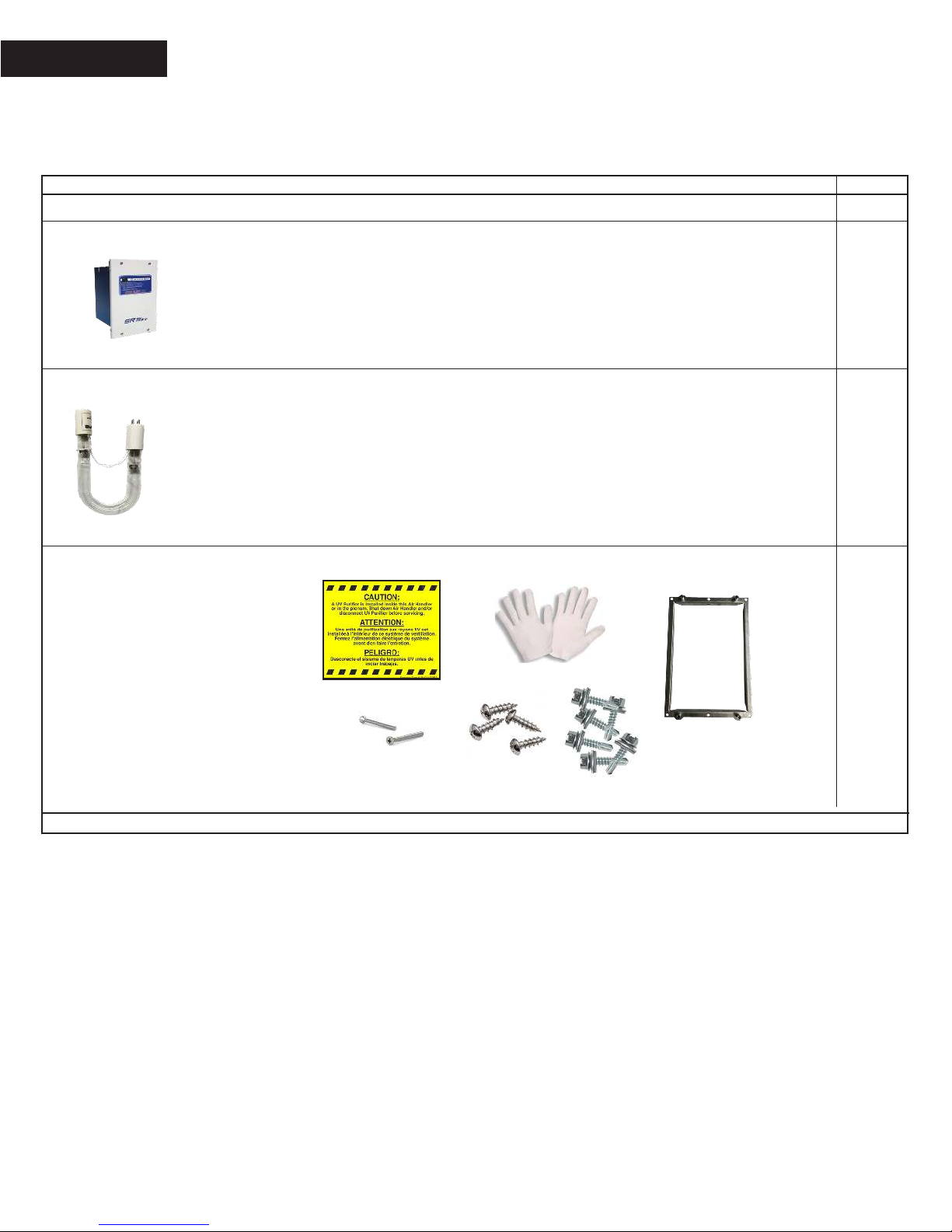
1.1 Remove the contents from the packaging. Only aer you
have visually inspected the UV lamp should you break the
security seal on the underside of the cardboard sleeve.
1.2 Carefully slide the UV lamp out from the cardboard sleeve.
Be sure to wear the cotton gloves (included)
guaranteeing a clean lamp free from ngerprints. Fingerprints
on the lamp will negatively impact the UV output of the lamp.
1.3 To install the UV lamp, remove the reecting tube
by removing the 4 screws on either side.
1.4 Slide the UV lamp porcelain end-cap (with 4 pins)
through the clamp. Use the wingnut to tighten the clamp
and secure the lamp. Do not over tighten the wingnut as this
could damage /break the UV lamp. Insert the lamp connector
over the 4 pins of the UV lamp.
1.5 Reinstall the reecting tube by making sure that
the turbulator is facing the airow so that it will slow down
the air as it passes in front of the UV lamp.
2. Prepare the duct (return or supply) for installation
2.1 Evaluate the ideal area for installing the air purier.
e reection chamber should always be parallel to the air-
ow. Ensure that the purier will t into the plenum
and position it keeping in mind to minimize plastics exposure
to direct UV light.
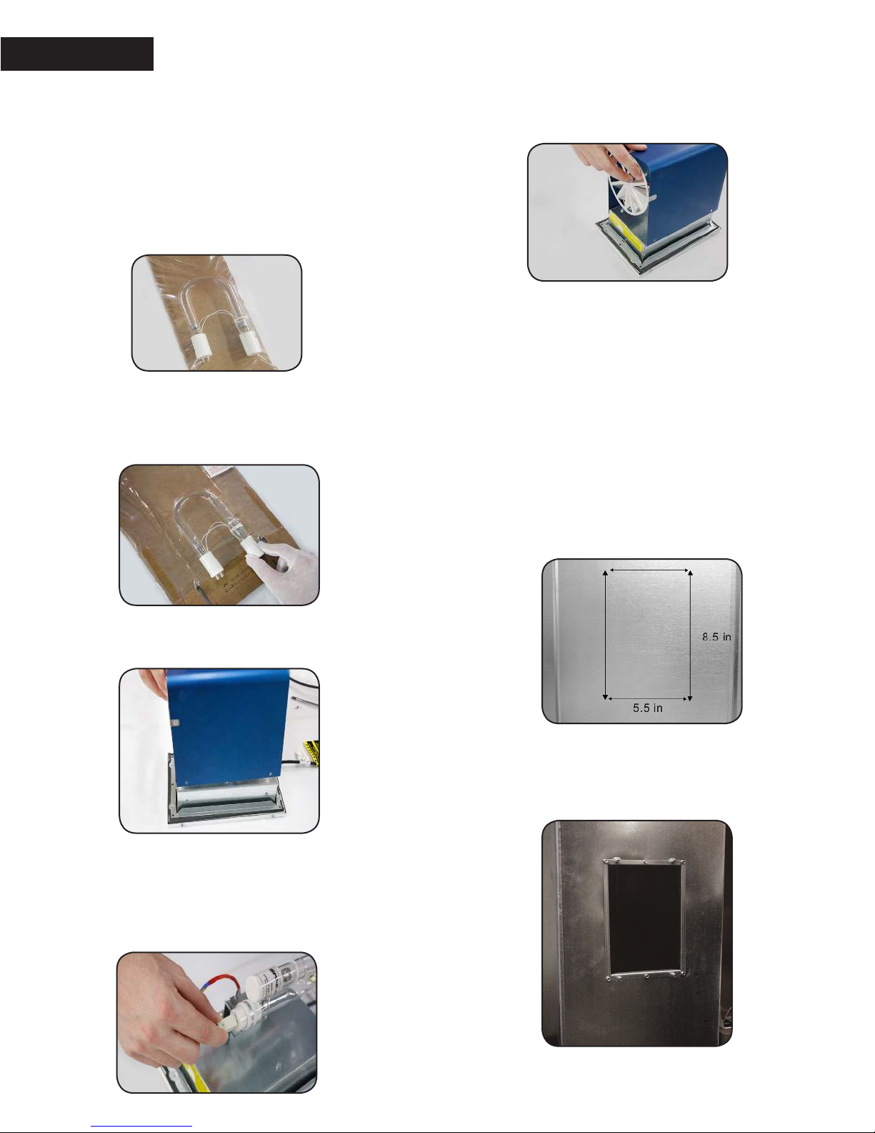
2.2 Use the included metal frame to trace the outline onto
the duct. Allow for a 1/8” space around the marking as to
allow the frame to sit properly in the duct. e duct opening
window should have the following dimensions: 8.5” x 5.5”.
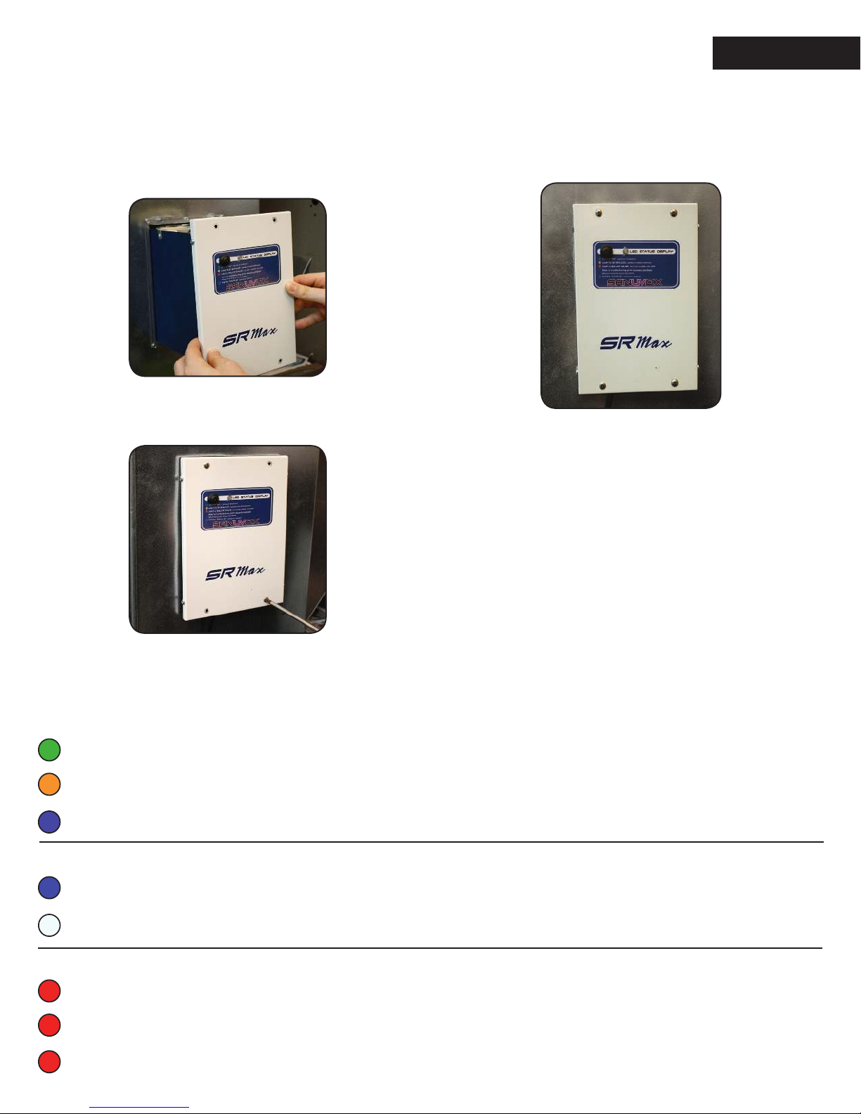
2.3 Cut out the window opening onto the duct. Place the frame
into the opening made in the duct and use the 6 metal screws
provided in the installation kit to secure it to the duct.

7
3. Finalize SRMax installation in the duct
and power ON
3.1 Place the SRMax into the frame, guided with
the alignment pins.
3.2 Secure the SRMax to the frame with the 4 remaining
screws located in the 4 corners of the SRMax cover.
3.3 Use the power cord of the unit to plug into a wall outlet
that provides the power as indicated on the marking label
of the product. An extension cord may be used if there is not
a power outlet close to where the SRMax is installed.
3.4 You are now ready to power ON your new SRMax
and enjoy great air quality for you and your family.
GREEN : In operation
ORANGE : Heartbeat followed by 1 ash - lamp over 3 years that needs to be replaced
BLUE : Heartbeat, stand-by waiting for airow
INFORMATION FROM THE STATUS LED
Normal operation
BLUE : Airow detection activated*
WHITE : Factory setting, airow detection de-activated
At start-up
RED (2 ashes) : Lamp or ballast failure
RED (3 ashes) : ermistor disconnected
RED (4 ashes) : ermistor shorted
Error code **
* Refer to the section below Activating airow detection ** Refer to troubleshooting (sanuvox.com/help)

8
RESET THE LAMP TIMER
Aer installing the lamp, make sure the timer function is reset.
1. To reset the lamp timer the unit needs to be powered and turned ON. e status LED should either be ‘Green’
or ‘Blue’ (heartbeat).
2. Use a small object similar to a paper clip and insert it into the hole in order to be able to press the reset button.
3. Press and hold the reset button for a minimum of 3 seconds. When releasing the reset button the counter will
be reset.
Replacement parts
Part Number Description
BST120/240GL Ballast with mutli-voltage input of 120 to 240V (50-60Hz)
LMPRGXJ65 T6 Regular Dual Zone (UVC / UVV) 6.5in “J” shape UV lamp
LMPRGJ65 T6 Regular Germicidal (UVC) 6.5in “J” shape UV lamp
ACTIVATING AIRFLOW DETECTION
(OPTIONAL)
e SRMax default factory mode, when the unit
is plugged in and the power switch is ON, will leave
the lamp ON at all times in order to reduce the cycling
strain on the lamp and improve its life.
It is possible to activate the airow detection if required.
e activation procedure is the following:
1. If your unit is powered ON, start by turning OFF
the power switch.
2. Use a small object similar to a paper clip and insert
it into the reset hole in order to be able to press
the reset button.
3. First, turn ON the power switch and then press
the reset button. You have 5 seconds from the moment
the unit is powered ON to press the reset button
to activate the airow detection.
Every time you press the button you will notice that the
LED color will either be “Blue” or “White”. When the
LED is “Blue” the airow detection is activated. Wait 5
seconds for the control circuit to save the setting.
4. From now on, the SRMax will only activate when
airow is detected in your duct system.
Table of contents
Other Sanuvox Air Cleaner manuals

Sanuvox
Sanuvox SR MAX User manual

Sanuvox
Sanuvox S300FX User manual

Sanuvox
Sanuvox VP900 User manual

Sanuvox
Sanuvox R MAX User manual

Sanuvox
Sanuvox SANUVAIR S100GX User manual

Sanuvox
Sanuvox S1000 User manual

Sanuvox
Sanuvox S300 User manual

Sanuvox
Sanuvox S300 User manual

Sanuvox
Sanuvox P900 User manual

Sanuvox
Sanuvox SANUVAIR S300 OZD User manual

Sanuvox
Sanuvox Quattro User manual

Sanuvox
Sanuvox SANUVAIR S100 User manual

Sanuvox
Sanuvox HRV6 User manual

Sanuvox
Sanuvox Quattro User manual

Sanuvox
Sanuvox Quattro User manual

Sanuvox
Sanuvox SRMax Programming manual

Sanuvox
Sanuvox SANUVAIR S600 User manual

Sanuvox
Sanuvox R1r User manual

Sanuvox
Sanuvox VP900 User manual

Sanuvox
Sanuvox FOODSAFE IL User manual