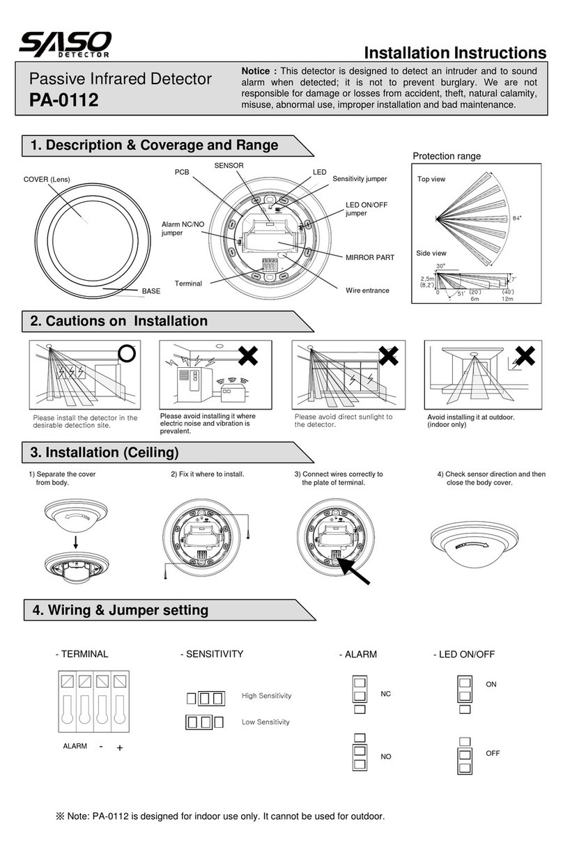
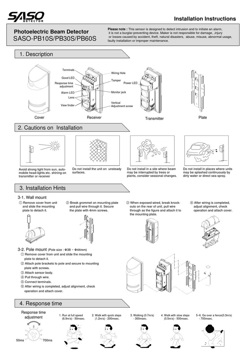
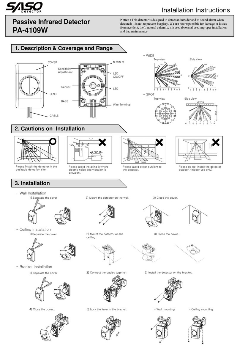
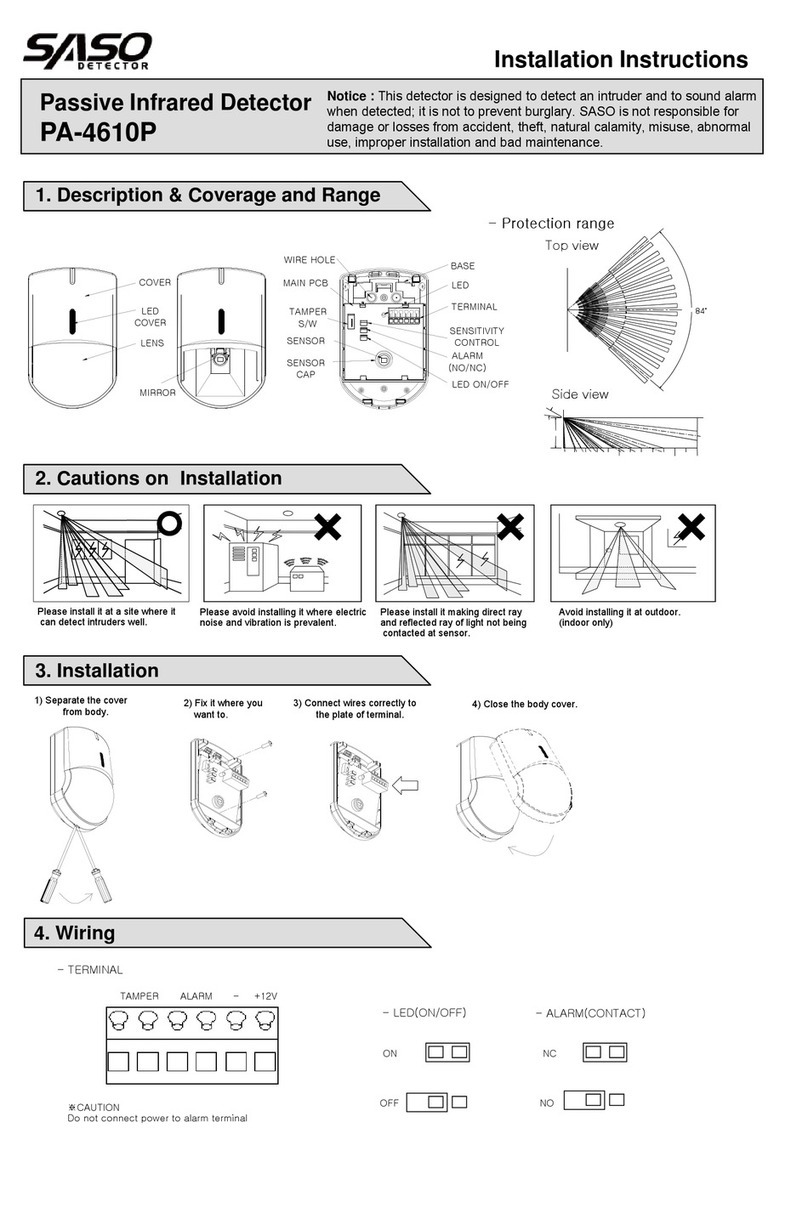
4. Protection distance and Expansion of beam
MODEL LA
SASO-PB30plus 30m 0.9m
SASO-PB60plus 60m 1.8m
SASO-PB30Alpha 30m 0.9m
SASO-PB60Alpha 60m 1.8m
Protection distance and Expansion of Beam
Protection distance L
A
5. Installation
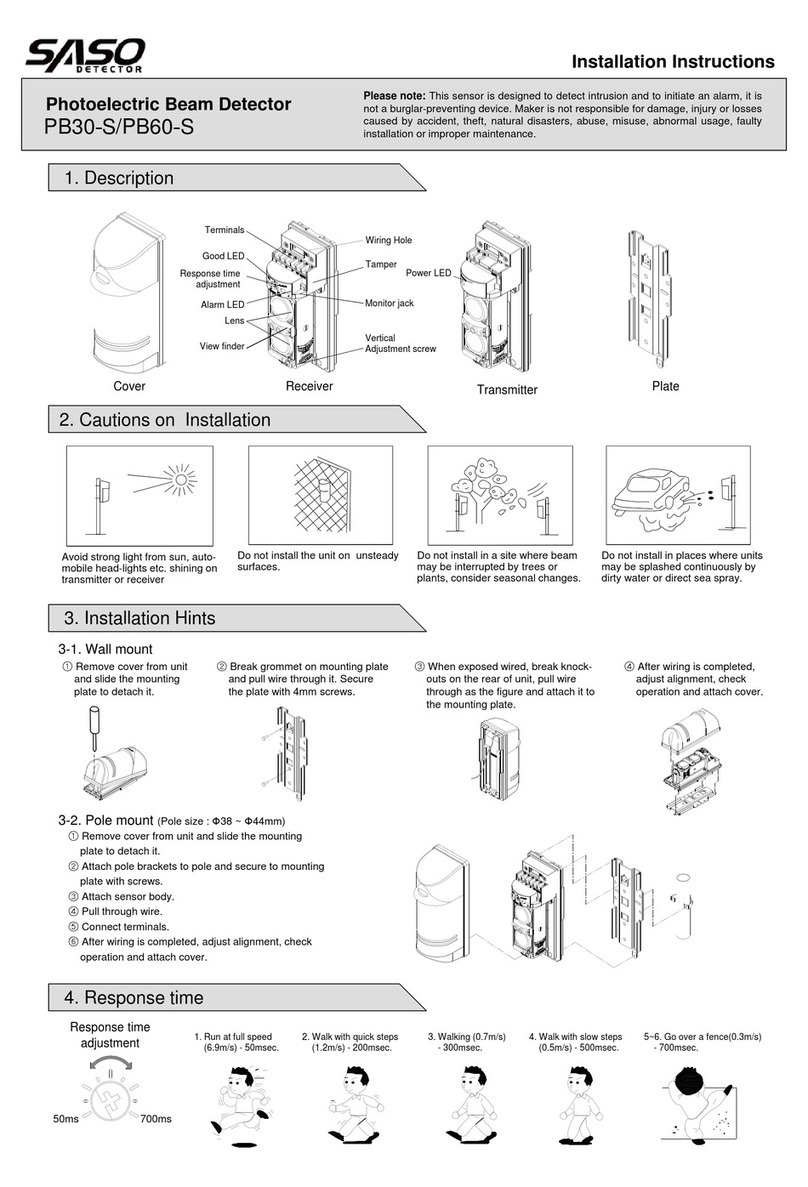
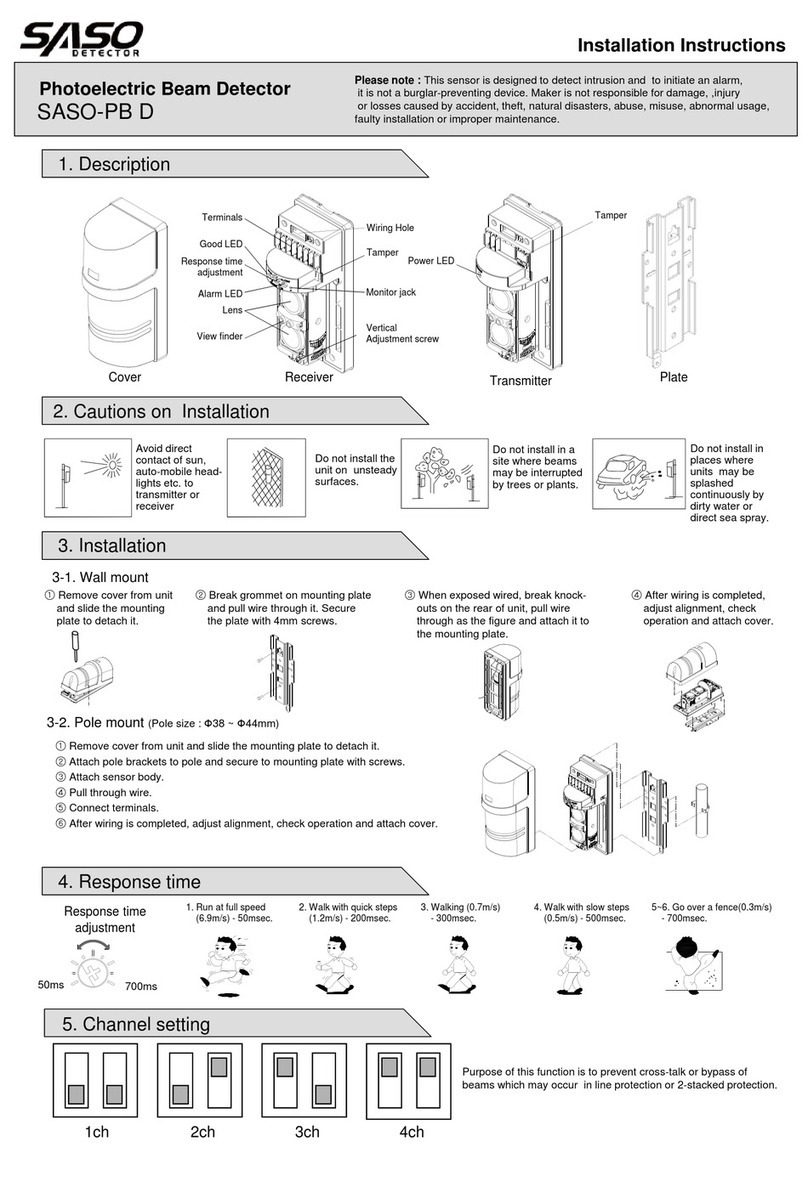
- Remove cover from unit
and slide the mounting
plate to detach it.
- Break grommet on mounting plate
and pull wire through it. Secure
the plate with 4mm screws.
- When exposed wired, break knock-
outs on the rear of unit, pull wire
through as the figure and attach it to
the mounting plate.
- After wiring is completed,
adjust alignment, check
operation and attach cover.
5-1. Wall mount
5-2. Pole mount
Wire hole
6. Optical Alignment
* Unit mounts to a 1.25”(40mm) - 1.80”(46mm)
(external diameter) pole
Read voltage from monitor jack with volt-meter(digital) to confirm optical
alignment and to obtain the highest reliability.
1. Supply power with cover detached.
2. Set Transmitter lens to Receiver lens by the view finder
Look through view finder on either side and line-up optics horizontally and vertically
until the opposite unit is visible. (Using the adjustment, the lens can move
horizontally(±90˚) and vertically(±10˚) allowing the unit to work in all directions )
middle mirror.
3. Adjust the Transmitter’s horizontally and vertically to get highest voltage reading.
Adjust the Receiver’s horizontally and vertically to get highest voltage reading.
- Reference table.
Monitor Jack Output Voltage Beam level
2.2V or over Good
180’
20’
4. Confirm the beam level by inserting a tester
in monitor jack of receiver.
2.0V under Readjustment
Receiver


