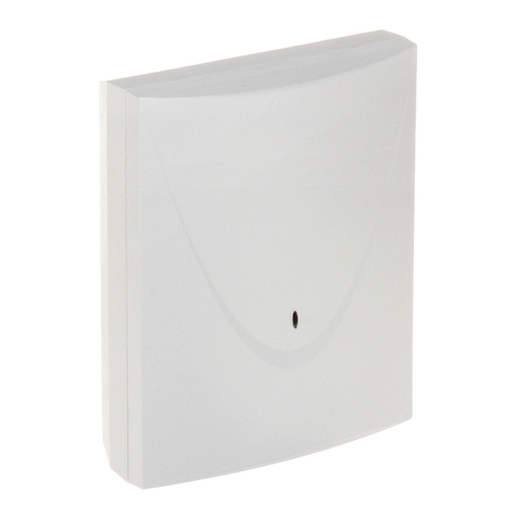
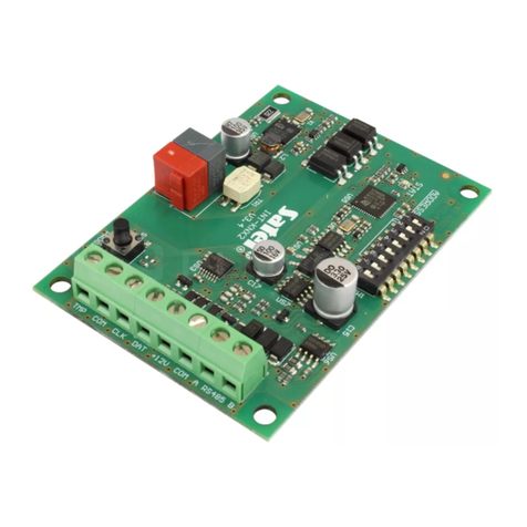
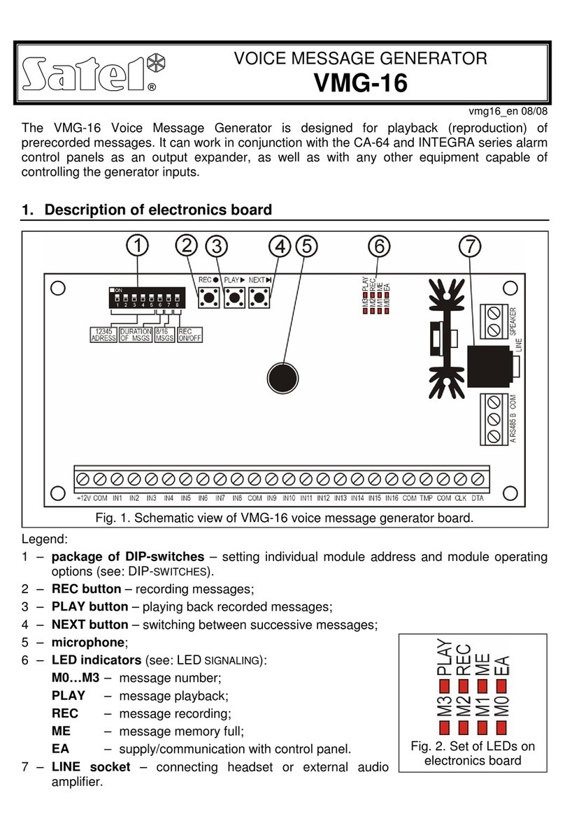
Satel INT-VMG User manual

®
VOICE MESSAGE GENERATOR
INT-VMG
int-vmg_en 05/15
The INT-VMG module allows loud playback of pre-recorded messages when certain events
occur. It can be used in conjunction with the INTEGRA control panels (as output expander),
and with any devices that are able to control the generator inputs. This manual applies to the
module with electronics version 2.1 and firmware version 1.00 (or later).
1. Features
Ability to record up to 32 messages.
Over 17 minutes for messages.
Managing voice messages by means of the free VMG-SOFT program.
Ability to record messages using the built-in microphone.
Control via the communication bus (INTEGRA control panels) or 16 inputs.
Built-in amplifier allowing direct connection of a loudspeaker.
Mini-jack for headphones or external audio amplifier.
Volume control for playback of messages.
Additional NC type tamper input.
2. Specifications
Supply voltage ................................................................................................... 12 V DC ±15%
Standby current consumption ..........................................................................................75 mA
Maximum current consumption......................................................................................500 mA
Recommended impedance of loudspeaker connected to SPEAKER terminals................... 8 Ω
Maximum power of speaker output......................................................................................6 W
Environmental class according to EN50130-5 ......................................................................... II
Operating temperature range..................................................................................-10...+55 °C
Maximum humidity..........................................................................................................93±3%
Dimensions of electronics board........................................................................... 68 x 140 mm
Weight................................................................................................................................. 80 g
The declaration of conformity may be consulted at www.satel.eu/ce
3. Functional description
The INT-VMG module connected to the control panel communication bus is recognized as an
output expander. Activation of an output assigned to the module results in the message
playback (the first output – message 0, the second output – message 1, etc.). The situation in
which a message is played back depends on how the output has been preprogrammed.
The message will also be played back after shorting the selected module input to ground.
This allows you to use any device for control. According to the factory settings, the inputs
trigger messages from 0 to 15 (the input 1 triggers the message 0, input 2 – message 1,
etc.). Messages having other numbers can be assigned to the inputs.
The module can queue up to 96 message playback commands.

2 INT-VMG SATEL
4. Electronics board
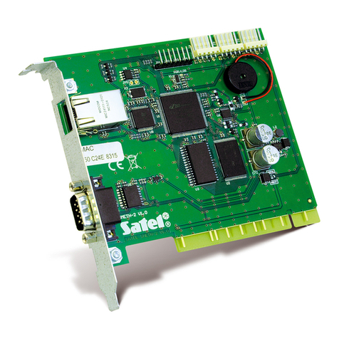
USB MINI-B socket for connecting the module to a computer and programming.
a set of DIP-switches for setting an individual address of the module and for defining its
operating parameters (see section DIP-
SWITCHES
).
PLAY LED – lit when the message is being played back.
REC LED – lit when the message is being recorded.
M4…M0 LEDs – present the message number. A number is assigned to each LED
(LED is ON – see Table 1; LED is OFF – 0). The sum of these numerical values
corresponds to the message number. The messages are numbered from 0 to 31.
LED M4 M3 M2 M1 M0
Number 16 8 4 2 1
Table 1. Numbers assigned to the LEDs which are lit (ON).
mini-jack socket for connecting a headset or an external audio amplifier.
connector for future applications.
connector used in the production process.
EA LED to indicate as follows:
blinking slowly – exchanging data with the control panel;
blinking fast – module USB port is connected to the computer;
lit – no communication with the control panel.

SATEL INT-VMG 3
REC button – starts the message recording with the built-in microphone.
PLAY button for:
playing back messages;
starting the volume control function;
changing the numbers of messages assigned to inputs.
microphone.
NEXT button for:
selecting the message number;
volume control;
starting the function to allow you change the message numbers assigned to inputs.
4.1 Description of terminals
+12V - power input.
COM - common ground.
IN1…IN16 - message triggering inputs.
TMP - tamper circuit input (NC) – if not used, it should be short-circuited to the
common ground.
CLK, DTA - terminals to connect the control panel communication bus.
A RS485 B - terminals to connect to RS-485 bus.
SPEAKER - terminals to connect the loudspeaker.
4.2 DIP-switches
The DIP-switches 1 to 5 are used to set the address. An individual address must be set in
the module, if it is connected to the control panel communication bus. A number is assigned
to each DIP-switch (in the ON position – see Table 2, in the OFF position – 0). The sum of
these numbers corresponds to the set address. These switches allow you to set an address
within the range from 0 to 31.
DIP-switch number 1 2 3 4 5
Number 1 2 4 8 16
Table 2. Numbers assigned to DIP-switches in ON position.
The DIP-switches 6 and 7 allow you to specify how many messages are to be triggered via
the communication bus. The number of messages corresponds to the number of system
outputs to be assigned to the module. The number of addresses that will be occupied by the
module depends on the number of messages/outputs (the panel will automatically assign the
consecutive addresses following the address set on the switches 1-5).
DIP-switch
6 7 Number
of messages Number
of addresses
OFF OFF 8 1
ON OFF 16 2
OFF ON 24 3
ON ON 32 4
Table 3. Number of messages and occupied addresses, depending on the setting of
DIP-switches 6 and 7.

4 INT-VMG SATEL
The DIP-switch 8 is used to enable/disable the recording of messages by means of built-in
microphone:
OFF – recording disabled;
ON – recording enabled.
5. Installation and start-up
Disconnect power before making any electrical connections.
The INT-VMG module should be installed indoors, in rooms with normal air humidity.
The description below is applicable to installation of the INT-VMG module which is to be used
in conjunction with the INTEGRA alarm control panel. If messages are to be triggered by
means of inputs, the input must be connected with wires to the outputs of the control devices.
If the module does not have to be connected to the communication bus, skip the steps 2, 3,
5, 8 and 9.
1. Secure the electronics board in the enclosure.
2. Using the DIP-switches, set the module address and specify the number of messages to
be triggered via the bus.
3. Connect the CLK, DTA and COM terminals with wires to the control panel expander bus.
To make a connection, it is recommended to use an unscreened straight-through cable.
When using the twisted-pair type of cable, the CLK (clock) and DTA (data) signals must
not be sent through one twisted pair. The wires must be run in one cable. The cable
length should not exceed 1000 m. If it exceeds 300 meters, it may be necessary to use
several wires connected in parallel for each signal.
4. Depending on your needs, connect the loudspeaker (to SPEAKER terminals), audio
amplifier or headset (to LINE socket).
5. Connect the tamper contact wires of module enclosure to the TMP and COM terminals. If
the module is not to monitor the tamper contact status, the TMP and COM terminals
should be shorted.
6. Connect power leads to the +12 V and COM terminals. The supply voltage can be taken
from the control panel or any power supply unit providing the 12 V DC output voltage.
7. Turn on the power supply. The LED designated EA will light up.
8. Start the expander identification function in the control panel. The module will be
recognized as an output expander. During the identification procedure, a suitable number
of outputs and addresses in the system will be assigned to the module.
9. Program appropriately the alarm system outputs assigned to the module:
select the output function, i.e. specify the circumstances in which the message is to be
played back;
make sure that the "Polarity" option is enabled for the output (if the polarity is
reversed, the message will not be played back properly);
if the message is to be played repeatedly, enable the "Pulsation" option (the message
will be played as many times, as the output is activated within the preset "Cut-off
time").
SATEL INT-VMG 5

6 INT-VMG SATEL
6. Manual operation of the module
6.1 Recording the messages
1. Set the DIP-switch 8 into the ON position.
2. Press the NEXT button to select the number of message to be recorded. The message
number is displayed on the LEDs as shown in Table 1 (p. 2).
3. Press the REC button (the REC LED will go on) and dictate the message content into the
microphone. The module has a system of automatic recording level control.
4. Press the REC button again to stop the recording (the REC LED will go off). The
recording will stop automatically after 16 seconds (to record longer messages, use the
VMG-S
OFT
program).
Note: It is recommended that the switch 8 be set into OFF position when the recording is
finished.
6.2 Listening to the recorded messages
1. Press the NEXT button to select the number of message to be played back. The message
number is displayed on the LEDs as shown in Table 1 (p. 2).
2. Press the PLAY button (PLAY LED will go on). The selected message will be played
back.
6.3 Volume control
1. Press and hold down the PLAY button for about 2 seconds. The LEDs shown in Figure 3
will blink three times and then will present the currently set volume (the more LEDs light
up, the higher the volume; all LEDs are lit – the maximum volume; no LED is lit – the
minimum volume).
2. Press the NEXT button repeatedly until the desired volume is set.
3. Press the PLAY button to exit the volume control function. The function will end
automatically if the NEXT button is not pressed for 10 seconds.
6.4 Changing the numbers of messages assigned to inputs
1. Press and hold down the NEXT button for about 2 seconds. The LEDs shown in Figure 3
will blink three times, and then the M0 ... M2 LEDs will tell you which message numbers
are currently assigned to the inputs:
M0 LED is lit – messages 0-15 (input 1 triggers message 0, input 2 – message 1, etc.);
M1 LED is lit – messages 8-23 (input 1 triggers message 8, input 2 – message 9, etc.);
M2 LED is lit – messages 16-31 (input 1 triggers message 16, input 2 – message 17,
etc.).
2. Press the PLAY button until the desired message numbers are assigned to the inputs.
3. Press the NEXT button to exit the message numbers changing function. The function will
end automatically if the PLAY button is not pressed for 10 seconds.

SATEL INT-VMG 7
7. VMG-Soft program
The VMG-Soft program allows synthesizing the messages and programming the module.
The installation file can be downloaded from www.satel.eu. The VMG-Soft program can be
installed on computers running Windows 2000/XP/VISTA/7.
The module and the computer on which the VMG-Soft program is installed should be
connected with a USB cable. The Windows system will automatically detect the connection of
a new device and will launch the wizard that will guide you through the procedure of
installation of drivers for your new hardware. The drivers can be downloaded from
www.satel.eu. Some versions of the Windows operating system may give you a warning that
the driver has not passed the compatibility test. Despite these warnings, installation of the
drivers should be continued.
Note: After the module is connected to a computer, all module functions are disabled and the
queue of messages to be played back is cleared.

SATEL sp. z o.o.
ul. Budowlanych 66
80-298 Gdańsk
POLAND
tel. + 48 58 320 94 00
www.satel.eu
Table of contents
Other Satel Control Unit manuals

Satel
Satel ETHM-1 Plus User manual

Satel
Satel ETHM-A User manual

Satel
Satel ETHM-A User manual

Satel
Satel MZ-1 User manual

Satel
Satel INT-KNX User manual

Satel
Satel GSM LT-2 User manual

Satel
Satel SATEL-TR49 SnapOn Quick setup guide

Satel
Satel SATELLINE-M3-TR1 User manual

Satel
Satel GSM-X User manual

Satel
Satel ETHM-1 Plus User manual