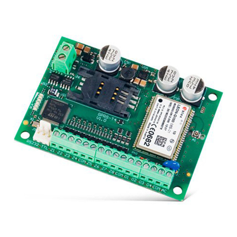
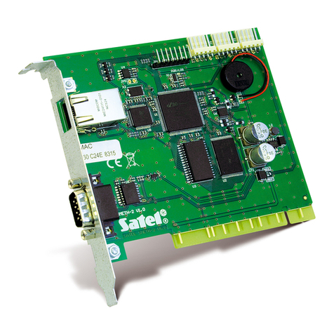
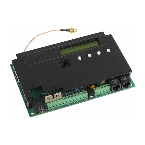
Satel GSM-4 User manual

Communication module
GSM-4/GSM-5
Firmware version 4.14 (GSM-4) / 5.14 (GSM-5) gsm4_5_en 11/12
SATEL sp. z o.o.
ul. Budowlanych 66
80-298 Gdańsk
POLAND
tel. + 48 58 320 94 00
www.satel.eu

WARNING
For safety reasons, the module should only be installed by qualified personnel.
Prior to installation, please read carefully this manual in order to avoid mistakes that can lead
to malfunction or even damage to the equipment.
Telephone terminals of the panel should be connected to PSTN lines only. Connecting to
ISDN lines may cause damage to the equipment.
Changes, modifications or repairs not authorized by the manufacturer shall void your rights
under the warranty.
CAUTION!
Never turn on power supply of the module and telephone without external antenna
connected.
Hereby, SATEL sp. z o.o., declares that this device is in compliance with the essential
requirements and other relevant provisions of Directive 1999/5/EC. The declaration of
conformity may be consulted at www.satel.eu/ce
The SATEL's goal is to continually upgrade the quality of its products, which may result in
alterations of their technical specifications and firmware. The current information on
the introduced modifications is available on our website.
Please visit us at:
http://www.satel.eu
The settings list, helpful in configuring the GSM-4 or GSM-5 module, is available in electronic
form at the www.satel.pl site
The following symbols may be used in this manual:
- note;
- caution.

SATEL GSM-4/GSM-5 1
CONTENTS
1.
G
ENERAL
............................................................................................................................3
2.
M
ODULE FEATURES
..............................................................................................................3
3.
T
YPICAL MODULE APPLICATIONS
............................................................................................4
3.1 B
ACKUP COMMUNICATION PATH
.................................................................................................. 4
3.2 S
UPERVISION
/
CONTROL OF DEVICES
.......................................................................................... 5
3.3 S
IMULATION OF MONITORING STATION
......................................................................................... 5
3.4 I
NTEGRATION WITH
INTEGRA
CONTROL PANELS
......................................................................... 6
3.5 W
ORKING IN CONJUNCTION WITH
STAM-1
/
STAM-2
MONITORING STATION
................................. 6
3.6 W
ORKING IN CONJUNCTION WITH
PBX
STATIONS
......................................................................... 7
4.
D
ESCRIPTION OF THE MODULE
..............................................................................................7
4.1 D
ESCRIPTION OF THE ELECTRONICS BOARD
................................................................................. 7
4.2 LCD
DISPLAY
.............................................................................................................................. 9
4.3 LED
INDICATORS
[
ONLY
GSM-5] ............................................................................................... 11
4.4 B
UTTONS
................................................................................................................................. 12
4.4.1 Module restart ...................................................................................................................................12
4.5 A
UDIBLE SIGNALING IN THE MODULE
.......................................................................................... 13
4.5.1 When controlling inputs.....................................................................................................................13
4.5.2 When controlling outputs...................................................................................................................13
4.5.3 In service mode.................................................................................................................................13
5.
I
NSTALLATION
....................................................................................................................13
6.
P
ROGRAMMING
..................................................................................................................14
6.1 S
ERVICE MODE
......................................................................................................................... 14
6.1.1 Service mode menu ..........................................................................................................................15
6.1.2 Description of functions available only in service mode ...................................................................21
6.1.3 Entering data by means of buttons ...................................................................................................21
6.2 D
LOAD
10
PROGRAM
................................................................................................................. 22
6.2.1 Local programming ...........................................................................................................................22
6.2.2 Remote programming .......................................................................................................................24
6.2.3 Main menu of D
LOAD
10 program ......................................................................................................25
6.2.4 Status bar..........................................................................................................................................26
6.2.5 Changing the program access code .................................................................................................26
6.2.6 "GSM-4 / GSM-5" tab........................................................................................................................27
6.2.7 "SIM 1/2" tab .....................................................................................................................................30
6.2.8 "Control/Inputs/Outputs" tab..............................................................................................................32
6.2.9 "Tel. messaging" tab .........................................................................................................................37
6.2.10 "Reporting" tab ..................................................................................................................................40
6.2.11 "Reporting – inputs" tab ....................................................................................................................44
6.2.12 "TCP/IP downloading" tab.................................................................................................................45
6.2.13 "Firmware update" tab.......................................................................................................................46
6.2.14 "Events buffer" tab ............................................................................................................................47
7.
C
ONTROL
..........................................................................................................................48
7.1 R
EMOTE
................................................................................................................................... 48
7.1.1 Tone control from telephone keypad ................................................................................................48
7.1.2 Using SMS ........................................................................................................................................49
7.1.3 Using CLIP ........................................................................................................................................50
7.2 L
OCAL
...................................................................................................................................... 50
7.2.1 Using the module buttons .................................................................................................................50
7.2.2 From the keypad of telephone connected to telephone line output..................................................51
7.3 C
ONTROL FROM
D
LOAD
10
PROGRAM
........................................................................................ 51
8.
S
TARTING THE REPORTING
.................................................................................................52
8.1 S
TARTING THE
GPRS
REPORTING
............................................................................................. 52
8.1.1 Reporting the module status (GPRS) ...............................................................................................53
8.1.2 Reporting events from the control panel (GPRS) .............................................................................53
8.2 S
TARTING THE
CSD
REPORTING
............................................................................................... 53
8.2.1 Reporting the module status (CSD) ..................................................................................................53
8.2.2 Reporting events from the control panel (CSD)................................................................................53
8.3 S
TARTING THE
SMS
REPORTING
............................................................................................... 54
8.3.1 Reporting the module status (SMS)..................................................................................................54
GSM-4/GSM-5 SATEL
2
8.3.2 Reporting events from the control panel (SMS)............................................................................... 54
8.4 S
TARTING THE
AUDIO
REPORTING
........................................................................................... 55
8.5 S
TARTING THE EVENT REPORTING OVER SEVERAL LINKS
............................................................ 55
9.
S
TARTING THE MESSAGING
.................................................................................................55
9.1 S
TARTING THE VOICE MESSAGING
............................................................................................. 55
9.2 S
TARTING THE
SMS
MESSAGING
.............................................................................................. 56
9.2.1 Changing the text messages content by means of SMS ................................................................. 56
9.3 S
TARTING THE
CLIP
MESSAGING
.............................................................................................. 56
10.
C
ONVERTING THE
PAGER
TYPE MESSAGES INTO
SMS
MESSAGES
........................................57
10.1 W
ORKING IN CONJUNCTION WITH THE
DT-1
DIALER
................................................................... 57
11.
S
ENDING
SMS
MESSAGES FROM THE TELEPHONE CONNECTED TO TELEPHONE LINE OUTPUT
....57
12.
T
HE RULES FOR CONVERTING THE NUMBERS
........................................................................59
13.
I
NITIATING THE MODULE FIRMWARE UPDATE BY
SMS
MESSAGE
..............................................59
14.
R
ESTORING THE FACTORY SETTINGS
....................................................................................59
14.1 D
LOAD
10
PROGRAM
................................................................................................................. 59
14.2 S
ERVICE MODE
......................................................................................................................... 60
14.3 M
ODULE FACTORY SETTINGS
(D
LOAD
10) .................................................................................. 60
15.
S
PECIFICATIONS
................................................................................................................62

SATEL GSM-4/GSM-5 3
1. General
This manual covers the GSM-4 module (electronics version 3.3, firmware version 4.14) and
the GSM-5 module (electronics version 1.2, firmware version 5.14).
2. Module features
Simulation of analog telephone line when using the GSM connection.
Capability of operating as a backup communication path for analog telephone line.
Built-in industrial GSM telephone working in 850/900/1800/1900 MHz cellular telephony
networks.
Support for two SIM cards (GSM-5 module).
Capability of remotely checking the status of available resources and the account validity
of SIM card installed in the module.
4 programmable hardwired inputs (NO, NC) to supervise the status of external devices.
3 programmable outputs to control the external devices or signal troubles.
An output to signal the telephone line trouble and/or problem with logging into GSM
network.
Control of outputs or bypassing of the module inputs by means of:
module buttons,
inputs,
telephone keypad (DTMF),
SMS messages,
CLIP (toll-free),
D
LOAD
10 program.
Capability of determining the telephone numbers authorized for DTMF or SMS control.
Messaging about the module related events to 4 telephone numbers in the form of:
voice message (played back by SM-2 synthesizer);
SMS message,
CLIP service (toll-free).
Reporting the module related events to two monitoring stations in Contact ID or Ademco
Express format.
Conversion and retransmission of event codes received from other devices (simulation of
the telephone monitoring station).
Several ways to send event codes to the monitoring station:
GPRS transmissions (encrypted),
CSD transmissions,
SMS messages,
AUDIO transmissions.
Defining the priority of different ways to report events.
Capability of storing up to 255 events generated by the module or received from
the control panel (modules with built-in GSM u-blox LEON-G100 telephone).
Capability of converting the PAGER type text messages into SMS messages.
Capability of limiting the outgoing calls made by means of GSM module telephone to the
indicated telephone numbers.

GSM-4/GSM-5 SATEL
4
Module programming:
locally: module buttons or computer with the D
LOAD
10
program installed, connected to
the module RS-232 port;
remotely: computer with the D
LOAD
10
program installed, connecting by means of
GPRS.
Display providing information on the module status and facilitating programming by means
of buttons.
RS-232 port to allow:
local programming by means of computer with the D
LOAD
10
program installed;
connection to the alarm control panel or computer as an external modem;
integration with the INTEGRA control panel;
working in conjunction with the STAM-1 / STAM-2 monitoring station;
updating the module firmware.
Capability of remotely updating the module firmware by means of GPRS (modules
with built-in GSM u-blox LEON-G100 telephone).
Powered with 12 V DC (±15%).
3. Typical module applications
The extended functionality of GSM module enables it to be used for a variety of applications.
This section presents typical examples of its application. Some of them are capable of being
combined with one other.
3.1 Backup communication path
Fig. 1. The module working as a backup communication path.
When connected to the telephone line output (T-1 and R-1 terminals, and in the GSM-4 –
also a suitable socket), the devices are capable of making telephone calls via analog
telephone line or GSM network. You can select which communication path will be the primary
one. If the primary communication path is malfunctioning, the module can automatically
switch over to the backup one.

SATEL GSM-4/GSM-5 5
3.2 Supervision / control of devices
Fig. 2. Module supervising operation of the devices connected to inputs and controlling
operation of the devices connected to outputs.
The change of status of the input to which the supervised device is connected may result in:
sending event code to the monitoring station (GPRS / CSD / SMS reporting);
notification (messaging) about the event by means of voice, SMS or CLIP message.
The inputs can be bypassed locally (by means of buttons, one of the module inputs or the
keypad of telephone connected to the telephone line output) or remotely (by means of SMS
messages or telephone keypad (DTMF)).
The devices connected to the module outputs can be controlled locally (by means of buttons,
module inputs or the keypad of telephone connected to the telephone line output) or remotely
(by means of SMS messages, telephone keypad (DTMF) or CLIP).
3.3 Simulation of monitoring station
Fig. 3. Module simulating the monitoring station.
The module can forward the event codes received from the control panel to the monitoring
station by means of GSM network. Which reporting link will be used to send the event code

GSM-4/GSM-5 SATEL
6
and when the module will acknowledge receipt of the code to the control panel depends on
the module configuration.
3.4 Integration with INTEGRA control panels
Fig. 4. Module working in conjunction with the INTEGRA control panel.
When connected to the INTEGRA control panel, the module offers the following benefits:
GSM network as the primary or backup communication path;
transmission of event codes to the monitoring station via GSM network;
messaging via GSM network, including SMS messaging (for the INTEGRA Plus
control panels, an additional feature is available: messaging by means of SMS
messages, whose content corresponds to the description in event log and thus the
installer does need to define it);
remote programming of the control panel from a computer with D
LOAD
X program
installed (with a fast data transfer due to GPRS);
remote management of the alarm system from a computer with G
UARD
X program
installed (with a fast data transfer due to GPRS).
The module can control connection with the INTEGRA control panel.
If communication with the GSM module is to be effected through the RS-232 port, the
local programming function in the INTEGRA control panel must be disabled.
3.5 Working in conjunction with STAM-1 / STAM-2 monitoring station
When connected to the STAM-1 / STAM-2 monitoring station, the module makes it possible
to receive event codes sent in the form of SMS or CLIP message. If used in conjunction with
the STAM-2 monitoring station, the module also enables the monitoring station to receive
CSD data transmissions containing the event codes and to send SMS messages.

SATEL GSM-4/GSM-5 7
Fig. 5. Module working in conjunction with the STAM-2 monitoring station.
3.6 Working in conjunction with PBX stations
The module can work in conjunction with the Private Branch Exchanges (PBX) as an
additional external telephone line. It can be used to make outgoing calls to the mobile phone
numbers and thus optimize the costs incurred.
4. Description of the module
4.1 Description of the electronics board
Description of the terminals:
OT1...OT4 – OC type outputs (shorted to ground when active):
OT1 -controlling output.
OT2 - controlling or monitoring trouble signaling output (see: "OT2 -
mon.trbl." p. 29).
OT3 - controlling or telephone line trouble signaling output (see: "OT3 -
t.l.trbl." p. 29).
OT4 - telephone line trouble and/or GSM network login problem signaling
output (see: „OT4 - only GSM" p. 29).
+V – power supply output (12 V DC ±15%).
IN1–IN4 – the module’s inputs.
-V – common ground (dedicated to external devices supplied from +V output).
The -V and GND are dedicated terminals for different applications and must not be
electrically connected.
+12V – power supply input (12 V DC ±15%).
GND – common ground.
– protective terminal of telephone communicator (connect only to the PE
protective circuit of 230 V AC mains).
T-1, R-1 – telephone line output (connection for alarm control panel, telephone set or
another device provided with telephone dialer).
When making a telephone call, the module changes the DC voltage polarization on
telephone line output (T-1 and R-1 terminals), thus enabling individual charging of the
phone calls.
TIP, RING – telephone line input (analog PSTN line).

GSM-4/GSM-5 SATEL
8
Fig. 6. View of GSM-4 module electronics board.
Explanations for Figures 6and 7:
GSM industrial telephone.
external antenna connection.
LCD display.
programming buttons.
STAT LED indicating the module status (see section "LED indicators [only GSM-5]"
p. 11).
SIG LED indicating the level of antenna signal received by GSM telephone (see section
"LED indicators [only GSM-5]" p. 11).
SIM1 and SIM2 LEDs indicating the SIM card with which the module is working.
SIM card socket (one in the GSM-4 module, two in the GSM-5 module). It is not
recommended that SIM card be inserted into the socket before the card PIN code has
been programmed in the module. The GPRS service must be activated in the SIM card
installed in the module, if the module is to use the functions requiring the GPRS
technology.

SATEL GSM-4/GSM-5 9
socket for connecting SM-2 voice synthesizer.
RS-232 port.
jack for external power supply unit .
telephone line output socket (for connection of alarm control panel, telephone set or
another device provided with telephone dialer).
telephone line input socket (analog PSTN line).
sounder.
Fig. 7. View of GSM-4 module electronics board.
4.2 LCD display
The integrated display allows you to read information about the module current status.

GSM-4/GSM-5 SATEL
10
Fig. 8. Information presented on the GSM module display.
Explanations for Figure 8:
the following symbols can be displayed here:
analog telephone line OK; flashing means an analog telephone line trouble;
telephone connected to telephone line output is off the hook.
the following information can be displayed here:
analog telephone line OK;
analog telephone line trouble.
the symbol can be displayed here, indicating that the module is controlled by an
external device (e.g. is working in the fax/modem mode). Flashing of the symbol means
data receiving or sending by the STAM-2 monitoring station.
the symbol can be displayed here, indicating the GSM telephone. The flashing symbol
means a GSM telephone trouble.
the following information can be displayed here:
GSM telephone OK;
GSM telephone trouble.
the symbol can be displayed here, indicating that the module is connected with the
computer through RS-232 port. Flashing of the symbol means data receiving or
sending.
The , and fields can display the name of the reporting link (GPRS, CSD or
SMS) over which the module is currently sending event codes to the monitoring
station.
the field presents information about the level of GSM signal received by the module
antenna. The displayed symbol denotes:
the signal level for the GSM-4 module or for the use of SIM1 card by the GSM-5
module;
the signal level for the use of SIM2 card by the GSM-5 module.
Flashing of the symbol means logging into the SIM card operator network.

SATEL GSM-4/GSM-5 11
symbols indicating the status of inputs / outputs are alternately displayed here (2s / 2s):
input violated;
input in normal state;
input blocked;
input violated, but changing its status does not start messaging ;
input status OK, but changing its status does not start messaging ;
output active; flashing means that the output will remain active for the preset time;
output inactive.
the following symbols can be displayed here:
modem connection;
outgoing call initiated by a device connected to the telephone line output and
made by the GSM module telephone;
incoming call to the GSM module telephone.
telephone number can be displayed here.
In the display lower line, the following items can be shown:
date and time,
message indicating occurrence of a specific event.
The display is also used when configuring the module settings. Press and hold down the
CHANGE and NEXT buttons simultaneously for about 1 second to display the service mode
menu. The functions are presented in two lines. An arrow is displayed on the left-hand side of
the currently selected function.
The display backlight illumination can be programmed so as to suit the user's needs.
4.3 LED indicators [only GSM-5]
Shown below in graphic form is how the module status is indicated by means of individual
LEDs. Each lighting scheme covers about 4 seconds and is repeated after 1 second pause
(– LED is OFF; – LED is ON).
STAT indicates the module status:
– (LED off) module power off,
– normal operation of module,
– no communication with GSM telephone,
– invalid PIN code,
– no PIN code,
– no SIM card,
– PUK code required,
– PH-SIM PIN code required,
– PIN2 code required,
– PUK2 code required,
– SIM card busy,
– module restart on switching power on,
– SIM card damaged,

GSM-4/GSM-5 SATEL
12
– invalid SIM card,
– other errors,
– active connection.
SIG indicates level of signal received by GSM telephone:
– no GSM network signal,
– level of signal 1,
– level of signal 2,
– level of signal 3,
– level of signal 4.
4.4 Buttons
The module PCB includes four buttons, which are used to program the device settings and
also to manually control the status of module inputs and outputs.
Button In service mode
(press and hold down the
CHANGE and NEXT keys for 1
second to enter the service
mode)
Bypassing /
unbypassing the
input (press the
button three times)
Activating /
deactivating the
output (press and
hold down the button
for about 1 second)
ESC 1.go to the "End of service"
function in the menu,
2.return from submenu to the
main menu,
3.exit from the function without
saving the changes.
bypassing /
unbypassing the input
IN1
activating /
deactivating the OT1
output
CHANGE 1.return to the previous function
in menu,
2.change of selected element in
the function (e. g. an option
marker , a digit or a letter).
bypassing /
unbypassing the input
IN2
activating /
deactivating the OT2
output
NEXT 1.move to next function item
within menu,
2.move to next element of the
function being programmed at
present (e. g. successive digit
or successive character).
bypassing /
unbypassing the input
IN3
activating /
deactivating the OT3
output
OK 1.entry into the function selected
from menu (indicated by arrow
on LCD display) for checking or
changing the settings,
2.exit from the function with
saving the changes.
bypassing /
unbypassing the input
IN4
deactivating the
OT1-3 outputs
4.4.1 Module restart
Press and hold down the ESC and OK keys simultaneously for 1 second to restart the
module. After the restart, information on the device firmware version will be displayed. The
status of inputs and outputs will remain unchanged.

SATEL GSM-4/GSM-5 13
4.5 Audible signaling in the module
4.5.1 When controlling inputs
3 short beeps – bypassing the input.
4 short beeps and 1 long beep – unbypassing the input.
4.5.2 When controlling outputs
3 short beeps – deactivating the single output or all outputs deactivating using buttons.
4 short beeps and 1 long beep – activating the output using buttons.
4.5.3 In service mode
2 short beeps – entering the service mode.
4 short beeps and 1 long beep – exiting the service mode.
1 short beep – going to the next or previous function in the service mode.
2 short beeps – entering the function.
2 long beeps – exiting the function without saving changes.
3 short beeps – saving the changes.
5. Installation
Disconnect power before making any electrical connections.
It is not advisable to power up the device if the antenna is not connected.
The GSM module should be installed indoors, in spaces with normal air humidity. When
selecting the mounting location, remember that thick masonry walls, metal partitions, etc. will
reduce the range of radio signal. It is not advisable to install the module in close vicinity to
electrical installations, because this can result in malfunctioning of the device.
The module power supply should have a sufficient output current and be provided with
a battery. It is recommended that it be placed at a distance of 3 m or less from the module.
When the supply voltage drops below 9.8 V, restart of the module occurs.
The +V and –V terminals should be used to supply the external devices. Remember that the
output current of the connected power supply unit must allow for electric demand of the
module and devices connected to it.
The following installation procedure is recommended:
1. Connect the antenna to the on-board connector
2. Connect the control panel, telephone or another device equipped with telephone dialer to
the R-1 and T-1 terminals (or to a suitable socket on the electronics board).
3. If the module is to be used as the external modem, connect the module RS-232 port to
the suitable port of the device.
4. Connect the analog telephone line to the TIP and RING terminals (or to a suitable socket
on the electronics board).
5. Connect the devices whose operation is to be monitored by the module to the input
terminals, as required.
6. Connect the devices to be controlled by the module to the output terminals.
7. Connect the power cables to the +12V and GND terminals.
8. Turn on power supply of the module.

GSM-4/GSM-5 SATEL
14
9. Using the suitable function, enter the PIN code(s) of SIM card(s) (if required by the SIM
card).
10.Turn off power supply of the module.
11.Insert the SIM card into the socket (see: Fig. 9).
123
456
Fig. 9. Installing the SIM card.
12.Turn on power supply of the module. Logging the telephone into the GSM network may
take a few minutes.
If the SIM card does not accept the PIN code, first the "Bad PIN, go on ? Wait…",
information is displayed, followed by the "Bad PIN, go on ? ESC=Stop" information (in
the GSM-5 module, the STAT LED will additionally indicate which PIN code is invalid).
The next attempt to use the PIN code will take place after 60 seconds. After the third
attempt to use the wrong PIN code, the SIM card will be blocked. To unblock the SIM
card, insert it into a mobile phone and enter the PUK code.
6. Programming
You can configure the module using the buttons located on the electronics board or the
computer with suitable software (locally and remotely).
6.1 Service mode
Programming the module by means of buttons on the electronics board is possible due to the
service functions, available in the service mode menu. To start the service mode, press and
hold down simultaneously the CHANGE and NEXT buttons. If required by the module, enter
the code to get access to the service mode (see "Service code" p. 27).
If no button is pressed for about 1 minute, the module will exit the service mode
automatically.
When the service mode is running, the control of inputs and outputs by means of
buttons is impossible.

SATEL GSM-4/GSM-5 15
6.1.1 Service mode menu.1.1 Service mode menu
The functions applicable only to the GSM-5 module are highlighted with white textThe functions applicable only to the GSM-5 module are highlighted with white text
against black background.
End of service
Service code
Line loss time
GSM loss time
Time of ringing
Turn off TLvolt
Show TL failure
Show dialing
Signal testing
CLIP -> number
Any numbers
Routing signal
GSM main line
Trbl.-switch l.
FLASH - GSM/TL
FLASH number
Outgoing No 1
Outgoing No 2
Outgoing No 3
Outgoing No 4
Perm. prefix 1
Perm. prefix 2
Perm. prefix 3
Perm. prefix 4
Prefix to erase
Prefix do add
Allowed numbers
Tel.No1 begin.
Tel.No2 begin.
...
Tel.No32 begin.
Messaging
Tel.1 for mess.
Tel.2 for mess.
Tel.3 for mess.
Tel.4 for mess.
Mess.x2 for t.1
Mess.x2 for t.2
Mess.x2 for t.3
Mess.x2 for t.4
Attempts/tel.1
Attempts/tel.2
Attempts/tel.3

GSM-4/GSM-5 SATEL
16
Attempts/tel.4
Ack. CLIP tel.1
Ack. CLIP tel.2
Ack. CLIP tel.3
Ack. CLIP tel.4
SMS mess 1 fail
SMS mess 2 fail
SMS mess 3 fail
SMS mess 4 fail
SMS IN1 violat.
SMS IN2 violat.
SMS IN3 violat.
SMS IN4 violat.
SMS fail. line
SMS IN1 restor.
SMS IN2 restor.
SMS IN3 restor.
SMS IN4 restor.
SMS restor.line
SMS test
SMS tst.w.state
TL ok, mess.IN1
TL ok, mess.IN2
TL ok, mess.IN3
TL ok, mess.IN4
IN1 -> Tel.
IN2 -> Tel.
IN3 -> Tel.
IN4 -> Tel.
F.L. -> Tel.
Rest.1 -> Tel.
Rest.2 -> Tel.
Rest.3 -> Tel.
Rest.4 -> Tel.
Rest.L -> Tel.
Test -> Tel.
CLIP -> Tel.
Test period
1st test random
Mess. priority
Mess. sounds
Msg.tel.control
All.tel.control
SMS control
SMS bypass IN1
SMS bypass IN2
SMS bypass IN3

SATEL GSM-4/GSM-5 17
SMS bypass IN4
SMS bypass all
SMS unbyps.IN1
SMS unbyps.IN2
SMS unbyps.IN3
SMS unbyps.IN4
SMS unbyps. all
SMS OT1 on
SMS OT2 on
SMS OT3 on
SMS OT1 off
SMS OT2 off
SMS OT3 off
SMS switch OT1
SMS switch OT2
SMS switch OT3
SMS OT123 off
SMS OT123 on
SMS check I/O
SMS "service"
SMS "user"
SMS mod. format
SMS test period
SMS change tel1
SMS change tel2
SMS change tel3
SMS change tel4
SMS restart
SMS USSD codes
Fwd.unknown SMS
DTMF control
DTMF bypass IN1
DTMF bypass IN2
DTMF bypass IN3
DTMF bypass IN4
DTMF bypass all
DTMF unbyps.IN1
DTMF unbyps.IN2
DTMF unbyps.IN3
DTMF unbyps.IN4
DTMF unbyps.all
DTMF check inps
DTMF OT1 on
DTMF OT2 on
DTMF OT3 on
DTMF OT1 off
DTMF OT2 off

GSM-4/GSM-5 SATEL
18
DTMF OT3 off
DTMF switch OT1
DTMF switch OT2
DTMF switch OT3
DTMF OT123 off
DTMF OT123 on
DTMF check outs
CLIP control
CLIP1 - tel. No
CLIP1 Outputs
CLIP2 - tel. No
CLIP2 Outputs
CLIP3 - tel. No
CLIP3 Outputs
CLIP4 - tel. No
CLIP4 Outputs
Inputs/Outputs
Input IN1 type
Input IN2 type
Input IN3 type
Input IN4 type
IN1 sensit.
IN2 sensit.
IN3 sensit.
IN4 sensit.
IN1 restore
IN2 restore
IN3 restore
IN4 restore
Autobps IN1 aft
Autobps IN2 aft
Autobps IN3 aft
Autobps IN4 aft
Autoreset IN1
Autoreset IN2
Autoreset IN3
Autoreset IN4
IN1 bypass time
IN2 bypass time
IN3 bypass time
IN4 bypass time
IN1 bps.manual.
IN2 bps.manual.
IN3 bps.manual.
IN4 bps.manual.
Bypassing input
Bypassed inputs
This manual suits for next models
1
Table of contents
Other Satel Control Unit manuals

Satel
Satel ETHM-1 Plus User manual

Satel
Satel GSM LT-1S User manual

Satel
Satel ETHM-1 User manual

Satel
Satel GPRS-T4 User manual

Satel
Satel MZ-1 User manual

Satel
Satel CA-64 ADR-MOD User manual

Satel
Satel INT-VMG User manual

Satel
Satel ETHM-1 User manual

Satel
Satel ETHM-1 Plus User manual

Satel
Satel INT-VG User manual
Popular Control Unit manuals by other brands

Universal Electronics
Universal Electronics JPN UE878 Quick reference guide

Gilson
Gilson ASPEC GX-271 Installation Qualification Procedures

Quectel
Quectel M85 Hardware design

Racelogic
Racelogic VB3iS Using

ADTRAN
ADTRAN Total Access 1500 FT1 DP Installation and Maintenance

Safeway water
Safeway water BNT85 Series Operation manual