2 INT-RX-S SATEL
3. Installation
Disconnect power before making any electrical connections.
The expansion module should be installed indoors, in spaces with normal air humidity. When
selecting the installation place, remember that the thick walls, metal partitions, etc. will reduce the
range of the radio signal. It is recommended that the expansion module be mounted high above the
floor. This will allow you to get a better range of radio communication and avoid the risk of the
expansion module being accidentally covered by people moving around the premises. Mounting the
expansion module near electrical installations is not advisable, as this may cause malfunction of the
device.
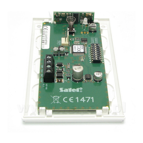
1. Open the enclosure of the expansion module (Fig. 2).
2. Make the opening in the enclosure base for the communication bus and
power cables.
3. Pass the cables through the opening. Use an unshielded non-twisted cable. If
you use the twisted-pair type of cable, the CLK (clock) and DAT (data) signals
must not be sent through one twisted pair.
4. Using wall plugs (screw anchors) and screws, fasten the enclosure base to
the mounting surface.
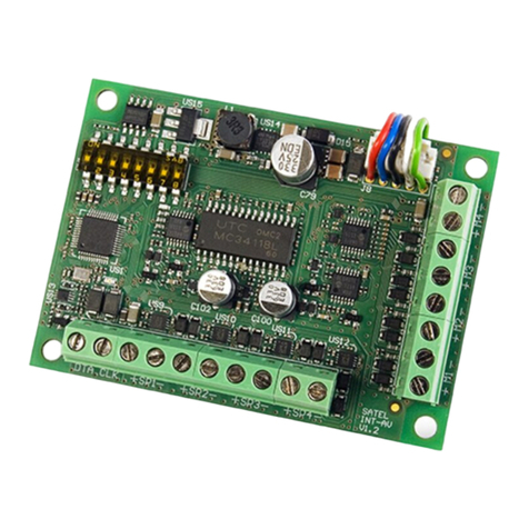
5. Connect the CLK, DAT and COM terminals with wires to the communication
bus of the control panel.
6. Connect the power leads to the +12 V and COM terminals. If the distance to
the control panel is less than 300 meters, the expansion module can be
supplied directly from the control panel. If the distance to the control panel is
higher, the expansion module must be supplied from another power source,
which is located at a closer distance (a power supply unit or an expander with
power supply).
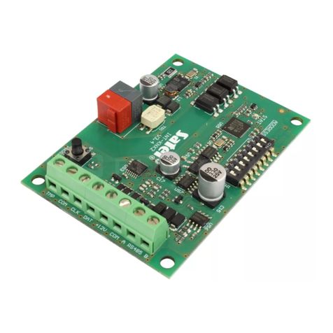
7. Using the DIP-switches, set the expansion module address. If the module is
connected to the VERSA / VERSA Plus / VERSA IP / PERFECTA 16 /
PERFECTA 32 control panel, set the address 7 (the switches 1-3 in ON
position, the other ones in OFF position).
Note: If you connect the module to the INTEGRA / INTEGRA Plus control panel,
to which the INT-RX / INT-RX-S module is already connected, the
address set on the new module must be higher than that on the module
already connected to the control panel.
8. Close the expansion module enclosure.
9. Power up the expansion module.
10. Depending on the control panel type:
alarm control panel: run the device identification function (for more information, refer to the
alarm control panel manual),
access control panel: add the expansion module to the system (for more information, refer to
the ACCO SOFT program manual).
Note: The keyfobs data are stored in the expansion module. If you connect to the alarm control
panel an expansion module in which keyfob data are stored, keyfobs will be assigned
automatically to the existing users.
4. Work with the INTEGRA / INTEGRA Plus control panel
If two or more INT-RX-S / INT-RX expansion modules are connected to the control panel, the keyfob
is supported by all of them. The keyfobs data are written automatically to all the expansion modules.
If you connect the expansion module to a control panel to which the INT-RX-S / INT-RX expansion
module is already connected, the keyfobs data must be unified. You can do it using:
DLOADX program – in the “Keyfobs INT-RX” window, click on the “Read” button and, immediately
after the data are read, click on the “Write” button (after reading the data, you must not make any
changes),
