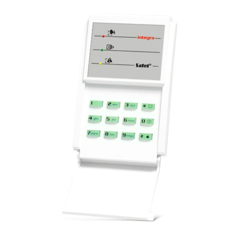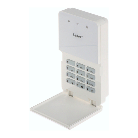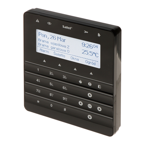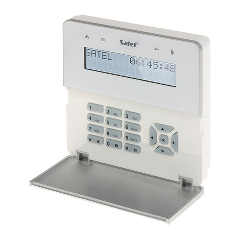
2 INT-SCR SATEL
1. Installation
The device should be installed by qualified personnel.
Disconnect power before making any electrical connections.
If an additional cable must be used to make connections, use the unshielded non-twisted
cable. If you use the twisted-pair type of cable, remember that CLK (clock) and DTA (data)
signals must not be sent through one twisted pair. The wires must be run in one cable.
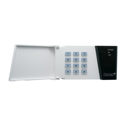
1. Open the keypad enclosure.
2. Place the enclosure base on the wall and mark the location of mounting holes.
3. Drill the holes for wall plugs (anchors).
4. Using wall plugs (anchors) and screws, secure the enclosure base to the wall. Select wall
plugs specifically intended for the mounting surface (different for concrete or brick wall,
different for plaster wall, etc.).
5. Close the enclosure and secure it with the screw.
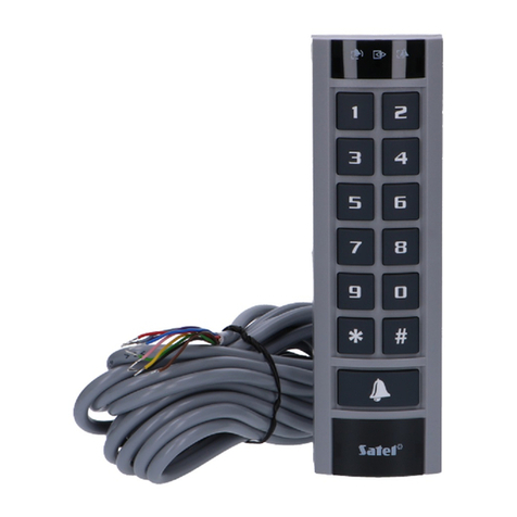
6. Connect the blue (COM), green (DTA) and black (CLK) wires to the appropriate terminals
of the control panel expander bus (see the control panel installer manual).
Fig. 2. Connecting the keypad to the control panel.
7. If the keypad is to control an electric strike, electromagnetic lock or another door actuator,
connect this device to the relay output as shown in Fig. 3. Depending on the device type,
use the following wires:
NC – pink (NC contact of the relay) and gray (C contact of the relay),
NO – yellow (NO contact of the relay) and gray (C contact of the relay).
It is not recommended that the door actuator be powered from the same source as the
keypad.
In the entry keypad mode, the relay output is disabled (you cannot control the
actuator).
