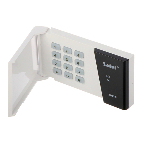
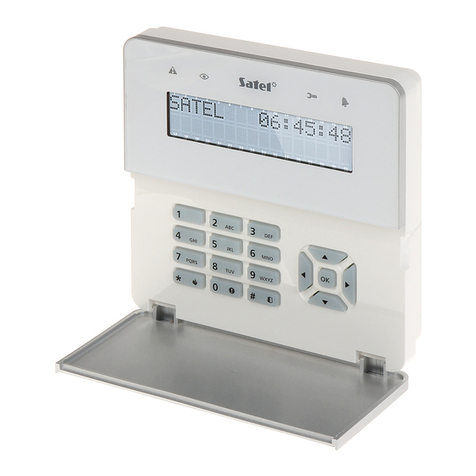
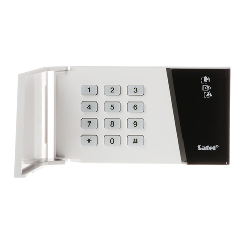
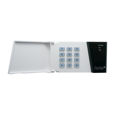
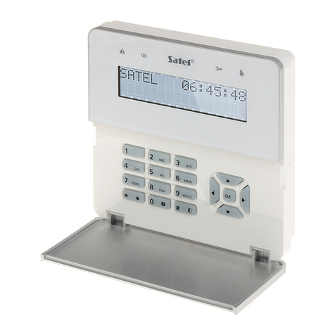
Satel INT-SCR-BL User manual

®
MULTIFUNCTIONAL KEYPAD
WITH PROXIMITY CARD READER
INT-SCR-BL
int-scr_en 06/12
The INT-SCR-BL multifunctional keypad with proximity card
reader can operate as:
partition keypad – a device supported by the CA-64 alarm
control panel, as well as INTEGRA control panels with
any firmware version, and identified as INT-S/SK. It is
designed to control arming of one partition. The device
makes it possible to execute the functions of access
control and electromagnetic door lock operation.
It enables changing the user code and calling the control
functions for outdoor devices, and identifies users by
their access code.
partition keypad with proximity card reader – a device
supported by the INTEGRA control panels with firmware
version 1.05 or later and identified as INT-SCR.
It performs identical functions as the partition keypad,
but allows the users to use proximity cards.
entry keypad – a device supported by the INTEGRA
control panels with firmware version 1.05 or later and
identified as INT-ENT. The main task of the entry
keypad is activation of the delay in the partition for the
zones with reaction type
3. I
NTERIOR DELAYED
. The time
period during which these zones will act as delayed
ones is programmable for the keypad. After expiry of the
programmed time, the interior delayed zones again act
as instant ones, unless the partition is disarmed.
Design of the keypad enables it to be installed outdoors.
The device is additionally equipped with a bell button to
control the OC type low-current output. Press the button to
short the output to the common ground.
This manual applies to the module with electronics version
1.4 and firmware version 2.01 (or later).
1. Description of the Keypad
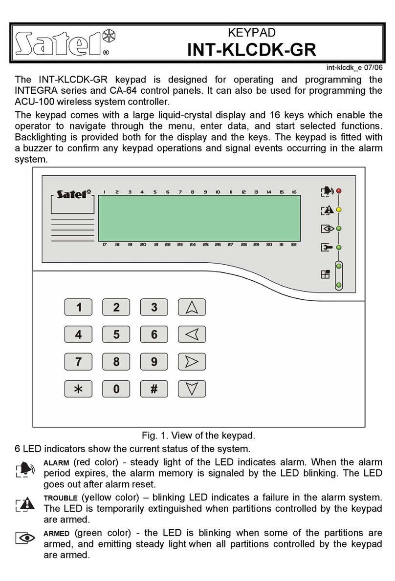
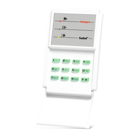
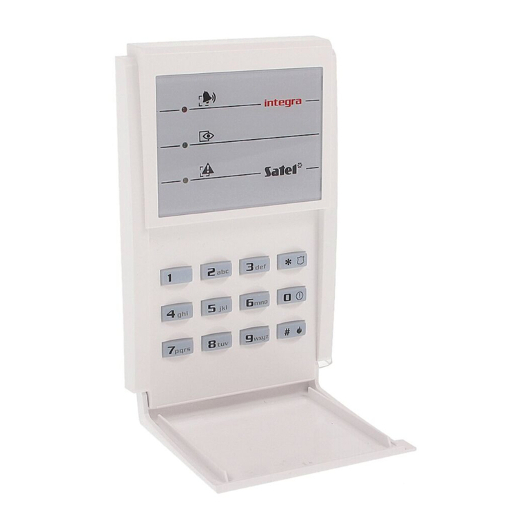
The partition keypad has 13 keys with permanent or
temporary (automatically activated) mode backlit and LED
indicators:
Fig. 1. INT-SCR-BL multifunctiona
l
keypad.
-
ALARM
(red color),
-
ARMED
(green color),
-
TROUBLE
(yellow color).
Information conveyed by means of the LED indicators depends on the keypad operating mode.
Alternative blinking of all the LEDs (from the left to the right) indicates lack of communication between
the keypad and the control panel. This situation may take place when the STARTER program is
running in the control panel, or when the cable connecting the keypad and the control panel is
damaged.

SATEL INT-SCR-BL2
Cable color Function
red power supply input (+12 V)
blue ground (COM)
green data (DTA)
black clock (CLK)
yellow relay NO contact (normally isolated from the relay common contact)
pink relay NC contact (normally shorted to the relay common contact)
grey relay C contact (common contact)
brown door status control input (NC type)
violet bell output (OC type)
Table 1. Colors and functions of the keypad cables.
2. Installation and Connection of the Keypad
In order to make connections of a greater length than the cable connected to the keypad allows, it is
recommended to use a straight-through unshielded cable. If the cable of "twisted-pair" type is used,
remember that the CLK (clock) and DTA (data) signals must not be transmitted through one twisted
pair of wires.
Any connections should only be made in deenergized state, i.e. with power supply
disconnected.
1. Remove the locking screw which prevents the casing from being opened and open the casing.
2. Attach the lower part of the casing to the wall.
3. Close the casing and replace the locking screw.
4. Connect the cables: blue (COM), green (DTA) and black (CLK) to the corresponding terminals of
the expander bus on the control panel PCB.
5. Connect the door status control detector to the brown and blue cables. If the door status is not to
be controlled, connect the brown cable to the blue one.
Note: In the entry keypad mode, the door status control detector is not supported.
6. An actuating device (e.g. electromagnetic door lock) can be connected to the relay cables. Use the
yellow and gray cables, if the device is to be activated by closing the circuit. If the device is to be
activated by opening the circuit, use the pink and gray cables.
Note: In the entry keypad mode, the relay is not supported.
7. Connect the module supply to the red (+12 V) and blue (COM) cables. The keypad supply voltage
is not to be necessarily provided from the control panel mainboard. A buffer power supply unit or
another expander with power supply unit can be used for this purpose.
8. The violet lead (bell) can be connected e.g. to the one of the control panel zones.
3. Operating Mode Selection and Address Setting
By default, address 0 and partition keypad operating mode with proximity card reader (INT-SCR) are
set in the keypad.
3.1 Changing the address
1. Turn off the keypad power supply.
2. Disconnect the green and black cables from the terminals of the control panel expander bus.
3. Short together the ends of the green and black cables.

INT-SCR-BL SATEL 3
4. Turn on the keypad supply. The keypad will generate 4 short beeps and 1 long beep, and the
LEDs designated [
ALARM
] and [
ARMED
] will start blinking alternately (the ends of green
and black cables can then be separated).
5. Press in turn the and keys. The keypad will confirm with 2 short beeps that the address
setting function has been launched, and the LED designated [
ALARM
] will start blinking.
6. Set the address within the range from 0 to 31, using suitable numerical keys and confirming your
selection with the key. The keypad will confirm with 4 short beeps and 1 long beep that the
address has been set. The LEDs designated [
ALARM
] and [
ARMED
] will start blinking
alternately (then, to proceed to setting the operating mode, press in turn the and keys).
7. Turn off power supply.
8. Connect the green and black cables correctly to the expander bus terminals on the control panel
mainboard.
3.2 Changing the operating mode
1. Turn off the keypad power supply.
2. Disconnect the green and black cables from the expander bus terminals.
3. Short together the ends of the green and black cables.
4. Turn on the keypad supply. The keypad will generate 4 short beeps and 1 long beep, and the
LEDs designated [
ALARM
] and [
ARMED
] will start blinking alternately (the ends of green
and black cables can then be separated).
5. Press in turn the and keys. The keypad will confirm with 2 short beeps that the operating
mode selection function has been launched, and the LED designated [
ARMED
] will start blinking.
6. Select the operating mode by pressing in turn:
and – partition keypad with proximity card reader (INT-SCR)
and – entry keypad (INT-ENT)
and – partition keypad (INT-S/SK)
The keypad will confirm with 4 short beeps and 1 long beep that the operating mode has been
selected. The LEDs designated [
ALARM
] and [
ARMED
]
will start blinking alternately (then,
to proceed to setting the address, ress in turn thep and ).
Turn off power supply.7.
black cables correctly to the expander bus terminals on the control panel8. Connect the green and
mainboard.
4. Starting the Keypad
1. Switch on the alarm system power supply.
2. Conduct identification of a new device in the alarm system. Call the
XPANDER IDENTIFICATION
Note: During the identification process, the control panel saves in the module memory a special
3. Afte panel, however most options
ith the computer and save the data to FLASH
memory.
E
function (
S
ERVICE MODE
S
TRUCTURE
H
ARDWARE
) from the LCD keypad.
(16-bit) number, used for checking the module presence in the system. Replacement of the
module with another one (even having the same address) without a new identification, will
result in triggering the alarm (module tamper – verification error).
r identification, the keypad will be supported by the alarm control
and functions will be disabled. For example, the lack of key press confirmation will make an
impression that the keypad does not react to entering the code. Using the LCD keypad or the
D
LOAD
X/D
LOAD
64
program, assign the users, who will be authorized to use the keypad and
program functions and options of the device.
4. Terminate the service mode or communication w

SATEL INT-SCR-BL4
5. Operation in the Partition Keypad Mode
The LEDs show following information:
off when alarm is cleared.
ALARM
(red color) – steady light indicates an alarm in the
blinking indicates that an alarm was triggered in the partitio
keypad controlled partition, while
n (alarm memory). The LED goes
ARMED
(green color) – steady light indicates that the partition to which the keypad is assigned
has been armed. Blinking indicates countdown of the exit delay.
TROUBLE
(yellow color) – blinking indicates that a technical problem has occurred.
e LCD keypad. Arming the
Note:
Informa keypad can be found in the user manuals of the control panels.
ICE MODE
Lo in the LCD keypad – its activation provides access to the Lock
Lo
X
)/Lock feature (
D
LOAD
64
) – its activation provides access to the lock feature options.
ac vice (e.g. electromagnetic door lock) by means of the partition keypad. This
entering the CODE and pressing the
The
signaling applies to troubles from the entire alarm system, not only from the keypad
controlled partition. The type of trouble can be checked on th
keypad controlled partition will disable the trouble signaling. Disarming the partition will
restore the trouble signaling.
All LEDs may be OFF in the arming mode, depending on the control panel settings.
tion on the use of the partition
The partition keypad can be programmed by means of the LCD keypad (
S
ERV
S
H
E
S
expander selection) or a computer with
TRUCTURE ARDWARE XPANDERS ETTINGS
the
D
LOAD
X
/
D
LOAD
64
program. Described below are settings and options available for programming
Abbreviations from the LCD keypad display are shown at some of the functions.
Name – option to give an individual (16-character) name to the module. This option can be accessed
in the LCD keypad as follows:
S
ERVICE MODE
S
TRUCTURE
H
ARDWARE
E
XPANDERS
N
AMES
expander selection.
Partition – assignment of the keypad to a partition selected from the list. The keypad controls this
partition.
ck feature – the option available
submenu.
ck (
D
LOAD
The options „Lock feature” (LCD / DLOAD64) and „Lock” (DLOADX) refer to support of the
tuating de
function is made available to any user authorized to use the keypad (see:
M
ASTER USERS
/U
SERS
function). Control is effected by means of the relay.
Lock features (
D
LOAD
X
)/Lock (
D
LOAD
64
)
ON if partition armed – the relay is active when the partition is armed, and inactive when the
partition is disarmed.
Note: When operating in this mode the relay will change its state automatically, if the partition is
disarmed from the given keypad. When the partition is disarmed from another keypad,
the state of the relay will change on key on the
Fixed O
given partition keypad.
N time [ON time] – after the user enters the CODE and presses the key, the relay will
ctive for the R
ELAY
ON
TIME
.be a
Fixed ON time – OFF if door open [ON, openoff] – after the user enters the CODE and presses
the key, the relay will be active until the door is opened (the door st us control input is
isolated from the common ground
at
), however not longer than for the
R
ELAY
ON
TIME
.
Fixed ON time – OFF if door closed [ON, closeoff] – after the user enters the CODE and
presses the key, the relay will be active until the door is closed (the door status control input
is shorted again to the common ground), however not longer than for the
R
ELAY
ON
TIME
.
Re
be s
lay ON time – the time period during which the relay is active. Duration of the „relay ON time” can
from 1to 255 econds.
INT-SCR-BL SATEL 5
Authorization control [Unauth. event] – opening the door without entering a password from the
keypad (e.g. with the key) will generate an „Unauthorized door opening” event, it can also be
Al
larm and can be additionally signaled on
Ma
rm. The duration can be set from 0to 255
De
ning of the door supervised by the module (activation of the relay). It allows to create a
Co
signaled on the output type 93
U
NAUTHORIZED ACCESS
.
arm on unauth. access [Unauth. alarm] – when the partition to which the module is assigned is
armed, unauthorized opening of the door will trigger the a
the output type 94
A
LARM
–
UNAUTHORIZED ACCESS
.
x. door open time – the time after expiry of which the module will report the „Long opened door”
event to the control panel and activate the audible ala
seconds.
pendent on door 1/Dependent on door 2 – you can define the door that must be closed so as to
enable ope
"sluice" type passage. You can indicate a door supervised by another alarm system expansion
module or zone programmed as the 57. TECHNICAL - DOOR OPEN type.
de+* do not disarm [Code
*
n. disarm] – with this option enabled, entering the code, confirmed by
pressing the key will neither disarm the partition nor activate the relay (will prevent the door
Ac
from being opened).
cess when armed [Code
*
in arm] – with this option enabled, entering the code, confirmed by
pressing the key will not disarm the partition, but it will activate the relay (and enable opening
Ma
larm – pressing and holding down for approx. 3 seconds the
of the door). The option is available when the
C
ODE
+*
DO NOT DISARM
[Code* n. disarm] is
enabled.
ster users/Users – this function defines master users / users authorized to use the given keypad.
Alarms
FIRE a key triggers the fire alarm.
eAUX. alarm – pressing and holding down for approx. 3 seconds th key triggers the medical
PANIC alarm – pressing and holding down for approx. 3 seconds the
alarm.
key triggers the
PANIC
Sil NIC alarm – pressing and holding down for approx. 3 seconds the
alarm.
ent PA key triggers the
Ala tered three times.
Op arming – with this option enabled quick arming function will be available:
silent PANIC alarm i.e. without a loud signaling, but only with sending a message to the
monitoring station and activating the 12.
S
ILENT ALARM
type of output.
rm 3 incorrect codes – an alarm will be triggered if a wrong code is en
tions
Quick
– fully armed mode – press in turn the and (keys (CA-64 and INTEGRA control panels
with any firmware version) or the and keys (INTEGRA control panel with firmware
version 1.05);
– fully armed mode plus bypassing zones with
B
YPASSED IF NO EXIT
option enabled - press in
turn the and
(
keys
(
INTEGRA control panel with firmware version 1.06 or later);
– armed without internal – after pressing in turn the and keys (INTEGRA control panel
with firmware version 1.05 or later);
– armed without internal and entry delay – after pressing in turn the and keys (INTEGRA
f the
B
ISTABLE OUTPUTS
type (control of the
Co pad can handle codes of the
MONO
OUTPUTS
type (activation of
Pa ich the keypad is assigned is armed, it can be blocked
control panel with firmware version 1.05 or later).
Control BI output – the keypad can handle codes o
type
25. BI
SWITCH
outputs).
ntrol MONO output – the key
the type
24. MONO
SWITCH
outputs).
rtition blocking – if the partition to wh
with the code of the
T
EMPORARY PARTITION BLOCKING
or
G
UARD
type (if the user is not

SATEL INT-SCR-BL6
authorized to disarm the partition). The zones of the blocked partition will not trigger the burglary
alarm. The blocking duration is defined individually for each user using the
T
EMPORARY
PARTITION BLOCKING
code type and for the partition (
B
LOCKED FOR GUARD ROUND
).
Guard round control – entering the guard code ended with or key will be recorded as
completion of the round.
Changing access code – the user code can be changed using the keypad.
Signaling
Alarm signal – the keypad will signal the partition alarm acoustically throughout the global alarm
duration.
Alarm signal (until canceled / latch) – the keypad will signal the partition alarm acoustically until
the alarm is cleared.
Signaling entry delay – the keypad is acoustically signaling the entry delay countdown.
Signaling exit delay – the keypad is acoustically signaling the exit delay countdown.
Auto-Arm delay countdown – the keypad is acoustically signaling the auto-arming delay time for
the partition.
Access code signaling (hardware) – the keypad itself, independently of the control panel, will
audibly acknowledge entering the access code. This signaling is useful if there is a delay
between the code entry and the audible information generated after verification of the code by
the control panel. Option is available only in the INTEGRA control panel.
CHIME - the module is acoustically signaling violation of the zones having the
CHIME
IN MODULE
option enabled and belonging to the same partition as the module.
Confirming – this option defines the way of communication between the control panel and the
partition keypad user:
No – the keypad provides no information on execution of or refusal to execute an operation.
Sound – the keypad provides information on execution of or refusal to execute an operation by
means of beeps (see: control panel user manual).
Backlight – the keypad provides information on execution of or refusal to execute an operation by
means of blinking of key backlight (see: control panel user manual).
Backlight – defines the mode of keypad illumination.
No – keypad backlit disabled.
Auto – keypad backlit goes on automatically on pressing any key; the function has additional
options (submenu
A
UTO
-
BACKLIGHT
in LCD keypad):
no auto-backlight – illumination only activated by pressing one of the keys,
zone violation – backlit activated by pressing a key or by violation of the indicated zone,
entry delay, part. – backlit activated by pressing a key or by starting the countdown of entry
delay time in the indicated partition.
Note: Automatic keypad illumination is ON for approx. 40 seconds from the moment of its
activation or from the last press of any key.
Permanent – keypad backlit is permanently “ON”.
No auto-reset after 3 tampers – you can disable the feature limiting to three the number of tamper
alarms from the expander (the feature prevents the same events from being logged repeatedly and
applies to the successive uncleared alarms).
Open door if fire [Doors on fire] – the fire alarm can have an effect on unblocking the door:
no – fire alarm has no effect on the door blocking,
partition fire alarm – fire alarm in the partition will unblock the door controlled by the module,
object fire alarm – fire alarm in the object will unblock the door controlled by the module,
fire alarm – fire alarm in the system will unblock the door controlled by the module.

INT-SCR-BL SATEL 7
6. Operation in the Mode of Partition Keypad with Proximity Card
Reader
Information conveyed by the keypad with LED indicators in this mode is identical to that in the
partition keypad mode. Additionally, all LEDs of the partition keypad with reader blinking
simultaneously indicate waiting for the card read-in (during the procedure of adding a card to
the user).
Information on the use of the partition keypad with proximity card reader can be found in the user
manual of the control panels.
The partition keypad with proximity card reader can be programmed by means of the LCD keypad
(
S
ERVICE MODE
S
TRUCTURE
H
ARDWARE
E
XPANDERS
S
ETTINGS
expander selection)
or a computer with the
D
LOAD
X
program. The operating mode of partition keypad with proximity card
reader offers all the functions available for the partition keypad mode. Support of the proximity cards
should only be additionally taken into account. Presenting the card to the reader is recognized by the
expander as entering the code, confirmed with the key. Holding up the card for approx. 3 sec. is
recognized as entering the code, confirmed with the key.
7. Operation in the Entry Keypad Mode
In the entry keypad, only the LED designated is used for signaling. Blinking of the LED informs
that the countdown of delay activation time is running (disarming has no effect on the LED blinking).
Information on the use of the entry keypad can be found in the user manual of the control panels.
The entry keypad can be programmed by means of the LCD keypad (
S
ERVICE MODE
S
TRUCTURE
H
ARDWARE
E
XPANDERS
S
ETTINGS
expander selection) or a computer with
the
D
LOAD
X
program. Described below are settings and options available for programming.
Name – option to give an individual (16-character) name to the module. This option can be accessed
in the LCD keypad as follows:
S
ERVICE MODE
S
TRUCTURE
H
ARDWARE
E
XPANDERS
N
AMES
expander selection.
Partition – assignment of the keypad to a partition selected from the list. The delay activation will
apply to the zones with reaction type
3. I
NTERIOR DELAYED
in this partition.
Master users/Users – this function defines master users/users authorized to use the given keypad.
Alarm 3 incorrect codes – entering a wrong code or reading in an unknown card three times will
trigger alarm.
Control BI output – the keypad can handle codes of the
B
ISTABLE OUTPUTS
type (control of the type
25. BI
SWITCH
outputs).
Control MONO output – the keypad can handle codes of the
MONO
OUTPUTS
type (activation of the
type
24. MONO
SWITCH
outputs).
Guard round control – entering the guard code ended with or key as well as presenting or
holding up the card will be recorded as completion of the round.
Signaling
Delay activation sign. – the keypad is acoustically signaling the countdown of delay unblocking
time.
Access code signaling (hardware) – the keypad itself, independently of the control panel, will
audibly acknowledge entering the access code. This signaling is useful if there is a delay
between the code entry and the audible information generated after verification of the code by
the control panel.
Confirming – this option defines the way of communication between the control panel and the
keypad user:
No – the module provides no information on execution of or refusal to execute an operation.
Sound – the module provides information on execution of or refusal to execute an operation by
means of beeps (see: control panel user manual).

SATEL INT-SCR-BL8
Backlight – the module provides information on execution of or refusal to execute an operation by
means of blinking of key backlight (see: control panel user manual).
Backlight – defines the mode of keypad illumination.
No – keypad backlighting disabled.
Auto – keypad backlighting goes on automatically on pressing any key.
Note: Automatic keypad illumination is ON for approx. 40 seconds from the moment of its
activation or from the last press of any key.
Permanent – keypad backlighting is permanently “ON”.
Delay activation time – the time period during which the zones with reaction type 3
. I
NTERIOR
DELAYED
(belonging to the partition to which the keypad is assigned) will act as delayed ones.
The countdown will start running after the code is entered or the card is read in. After expiry of the
programmed time, the interior delayed zones will again act as instant ones, unless the partition is
disarmed.
No auto-reset after 3 tampers – you can disable the feature limiting to three the number of tamper
alarms from the expander (the feature prevents the same events from being logged repeatedly and
applies to the successive uncleared alarms).
8. Specifications
Supply voltage ..................................................................................................................12 V DC ±15%
Standby current consumption...................................................................................................... 105 mA
Maximum current consumption ................................................................................................... 125 mA
BELL output load capacity............................................................................................................. 30 mA
Reader operating frequency ....................................................................................................... 125 kHz
Relay contacts rating (resistive load)..................................................................................2 A / 24 V DC
Environmental class ............................................................................................................................. IV
Operating temperature range ............................................................................................... -25...+55 °C
Maximum humidity........................................................................................................................ 93±3%
Dimensions.................................................................................................................. 47 x 158 x 24 mm
Cable length .......................................................................................................................................4 m
Weight .............................................................................................................................................297 g
The declaration of conformity may be consulted at www.satel.eu/ce
SATEL sp. z o.o.
ul. Schuberta 79
80-172 Gdańsk
POLAND
tel. + 48 58 320 94 00
www.satel.eu
Table of contents
Other Satel Keypad manuals

Satel
Satel INT-S User manual

Satel
Satel INT-TSG2 User manual

Satel
Satel INT-SCR User manual

Satel
Satel INT-TS User manual

Satel
Satel INT-TSG2 Owner's manual

Satel
Satel INT-TSG User manual

Satel
Satel INTEGRA INT-TSH2 User manual

Satel
Satel Integra INT-KSG2R User manual

Satel
Satel INT-TSG2 User manual

Satel
Satel MKP-300 User manual

Satel
Satel INT-TSI User guide

Satel
Satel INT-KWRL User manual

Satel
Satel VERSA INT-TSH2 Owner's manual

Satel
Satel INT-TSG2 User manual

Satel
Satel INT-KSG Instruction manual

Satel
Satel INT-KWRL2 User manual

Satel
Satel CA-6 KLED-S User manual

Satel
Satel VERSA INT-TSH2 User manual

Satel
Satel abax2 User manual

Satel
Satel INT-TSG User guide