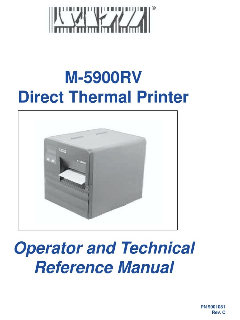
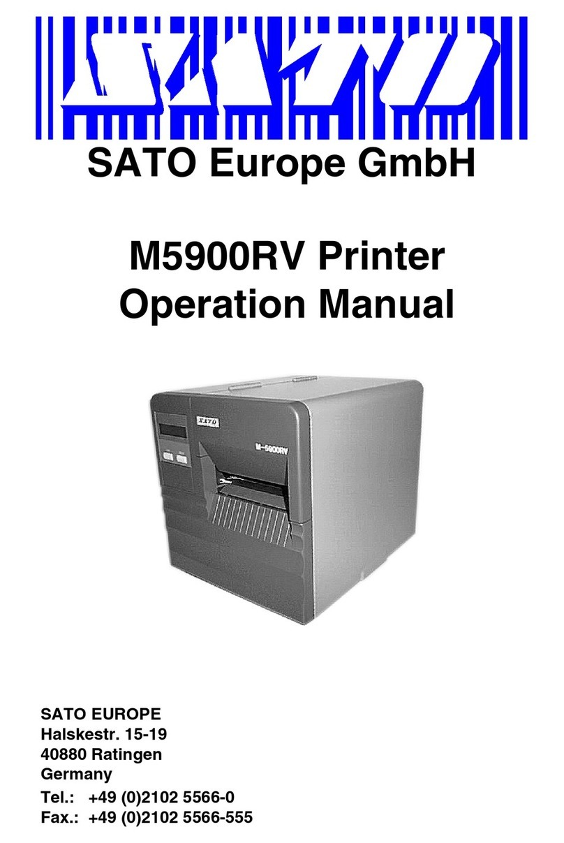
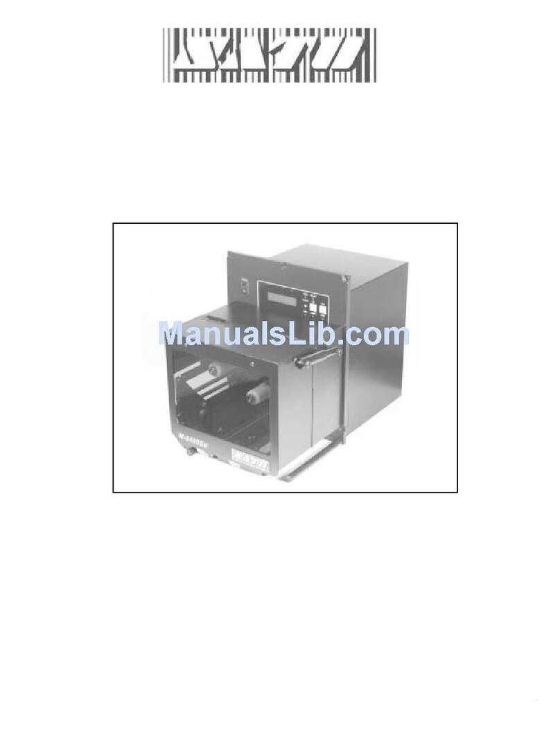
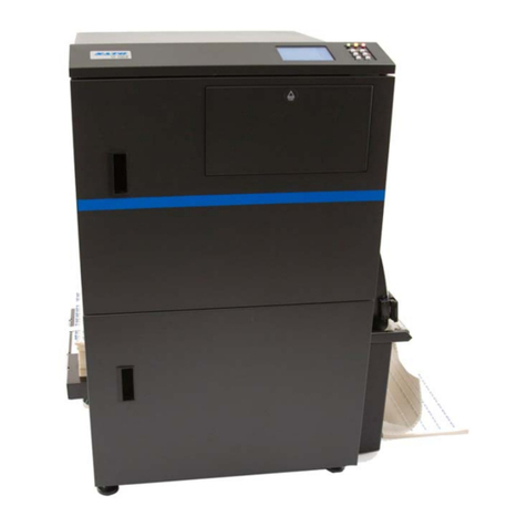
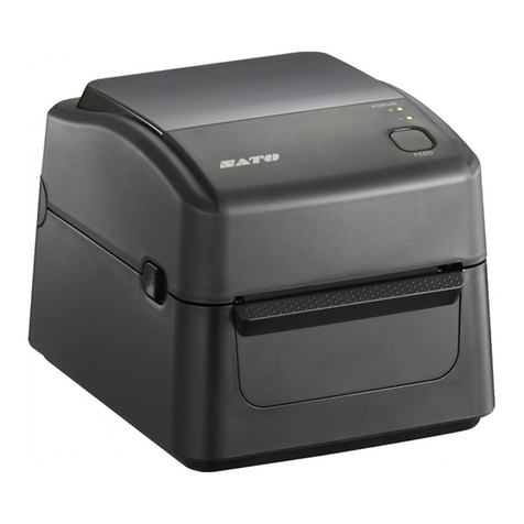
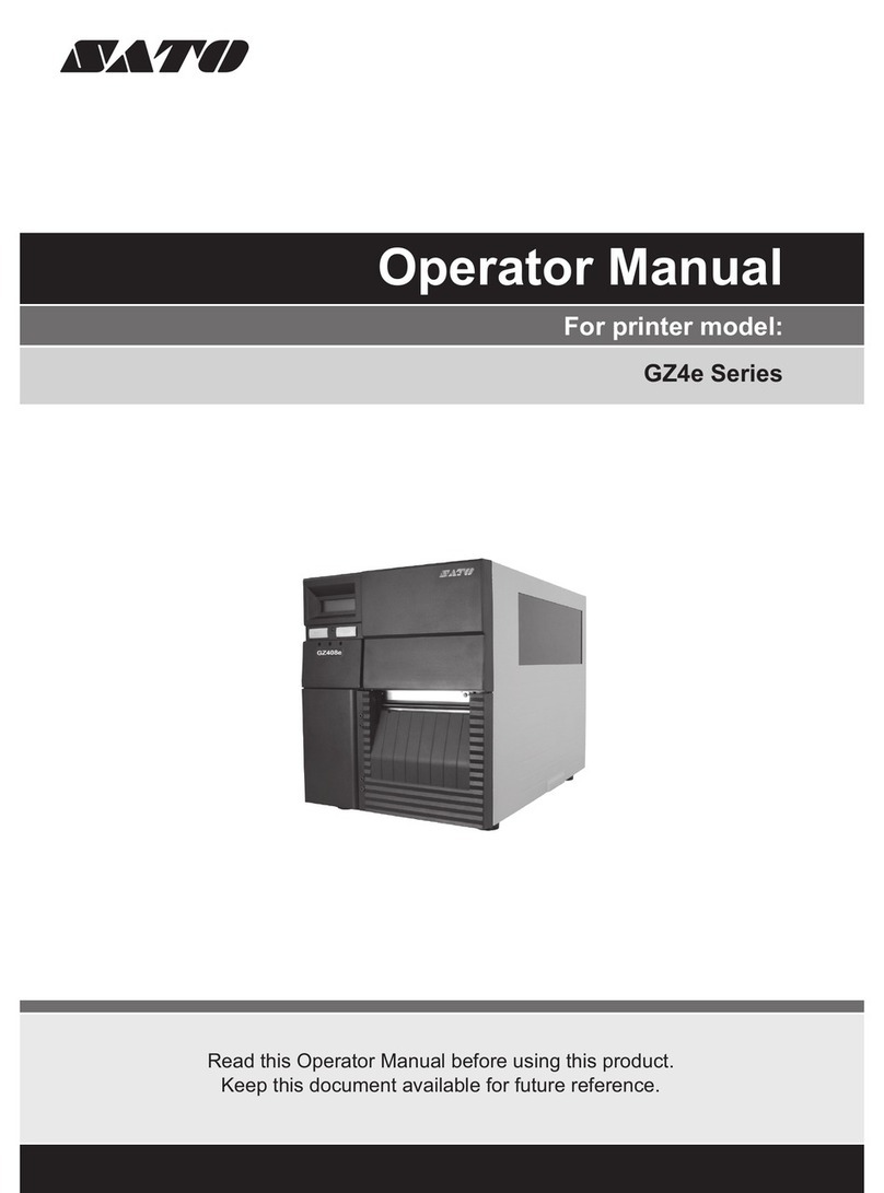
SATO GL4 Series User manual

GL4xxeSeries
OPERATOR’SMANUAL

SATO International Pte Ltd
438A Alexandra Road
#05-01/02
Alexandra Technopark
Singapore 119967
Tel: (65) 6271 2122
Fax: (65) 6271 2151
Email: customerser[email protected]
Be sure to ask your dealer about our maintenance contracts
to ensure peace of mind during your usage of SATO products
Version: SI-GL4xxe-01rA-01-12-OM
© Copyright 1994 – 2007
SATO International Pte Ltd
Warning: This equipment complies with the requirements in Part 15 of FCC rules for a Class
A computing device. Operation of this equipment in a residential area may cause
unacceptable interference to radio and TV reception requiring the operator to take whatever
steps are necessary to correct the interference.
All rights reserved. No part of this document may be reproduced or issued to third parties in
any form whatsoever without the express permission of SATO. The materials in this
document are provided for general information and are subject to change without notice.
SATO assumes no responsibilities for any errors that may appear.

i
TABLE OF CONTENTS
OVERVIEW
1.1 General Specifications ........................................................................................1-1
INSTALLATION
Safety Precautions.....................................................................................................2-2
2.1 Unpacking.............................................................................................................2-4
2.1.1 Included Accessories.......................................................................................2-5
2.1.2 Parts Identification............................................................................................2-6
2.2 Loading the Carbon Ribbon (For Thermal Transfer Printing)..........................2-10
(Note: Ribbon is not needed for Direct Thermal printing)......................................2-10
Adjusting the Ribbon Guide .....................................................................................2-11
(Note: Ribbon is not needed for Direct Thermal printing)......................................2-11
2.3 Loading Labels And Tags ...................................................................................2-12
2.3.1 Loading Roll Paper ........................................................................................2-13
2.3.2 Loading Fanfold Paper from the rear ..............................................................2-15
2.3.3 Loading Fanfold Paper from under the printer ................................................2-16
2.3.4 Adjusting the Paper Sensor .............................................................................2-17
2.4 Replacing the Print Head2-18
2.5 Turning the printer ON/OFF ................................................................................2-19
CONFIGURATION AND OPERATION
3.1 ThE LCD and OPERATION PANEL.....................................................................3-1
3.2 The ICON-BASED MAIN MENU...........................................................................3-2
3.3 PRINTER OPERATION MODES...........................................................................3-3
ONLINE And OFFLINE Modes...................................................................................3-3
3.3.1 ONLINE Mode ................................................................................................3-3
3.3.2 OFFLINE Mode ..............................................................................................3-3
3.4 User Mode............................................................................................................3-4
3.4.1 Setting the Pitch Offset ...................................................................................3-5
3.4.2 Setting Print Speed ........................................................................................3-5
3.4.3 Setting Ver/Hor Print Offsets ..........................................................................3-6
3.4.4 Specifying the Protocol Command Code ....................................................3-6
3.4.5 Specifying the Ver/Hor Base Reference Points ...........................................3-7
3.5 Interface Mode......................................................................................................3-8
3.6 Advanced Mode ...................................................................................................3-16
3.7 Diagnostics Mode ................................................................................................3-21
3.8 Configurations Mode...........................................................................................3-23
3.9 Emulations Setup Mode ......................................................................................3-23
3.10 Understanding Continuous Print and Tear Off Operations ...........................3-24

ii
CLEANING AND MAINTENANCE
4.1 Introduction ..........................................................................................................4-1
4.2 Cleaning The Print Head, Platen and Rollers ....................................................4-1
4.3 How To Clean The Printer (Cleaning SET).........................................................4-2
4.4 How To Clean The Printer (Cleaning SHEET)....................................................4-3
4.5 Adjusting Print Quality ........................................................................................4-4
4.5.1 Adjusting Print Darkness .............................................................................4-4
4.5.2 Adjusting Print Speed ..................................................................................4-4
TROUBLESHOOTING
5.1 Initial Checklist.....................................................................................................5-1
5.2 Using the Centronics (Parallel) Interface...........................................................5-1
5.3 Using the RS232C (SERIAL) Interface................................................................5-3
5.4 Understanding the STATUS INDICATORS.........................................................5-4
5.5 Understanding the LCD Error Messages ...........................................................5-5
5.6 Troubleshooting Guide........................................................................................5-10
OPTIONAL ACCESSORIES
6.1 Introduction ..........................................................................................................6-1
6.2 Available Interface Boards ..................................................................................6-1
6.3 Label Management Accessories.........................................................................6-2
6.3 PCMCIA Memory Cartridge .................................................................................6-3
6.3.1 Installing the memory card ...........................................................................6-3

Section 1: Introduction
GL Series Operator’s Manual Page 1-1
1
OVERVIEW
Thank you for your investment in this SATO printer product.
This Operator’s Manual contains basic information about the installation, setup,
configuration, operation and maintenance of the printer.
A total of seven topics are covered herein, and they are organized as follows:
Section 1: Overview
Section 2: Installation
Section 3: Configuration and Operation
Section 4: Cleaning and Maintenance
Section 5: Troubleshooting
Section 6: Optional Accessories
It is recommended that you become familiar with each section before installing and main-
taining the printer. Refer to the Table Of Contents at the front of this manual to search
for the relevant information needed. All page numbers in this manual consist of a section
number followed by the page number within the stated section.
For specialized programming, refer to the separate Programming Manual located on the
utility CD-ROM.
1.1 GENERAL SPECIFICATIONS

Section 1: Introduction
Page 1-2 GL Series Operator’s Manual
The SATO GL4XX “e” series of dual use (Thermal Transfer and Direct Thermal) printers
are complete, high-performance labeling systems designed for printing tags and labels.
The key features of the GL series are:
• Availability in 203dpi or 305dpi models
• High print speed of up to 10 inches per second
• User-changeable print head and platen mechanism for faster maintenance
• Supports longer lengths of labels and ribbon for reduced downtime
• Supports core-based media
• RFID ready, via optional add-on RFID kit
• Easy operation via large LCD and multiple control buttons and status indicators
• ODV option
• Rich emulation of printer languages (IPL, ZPL, DPL, TEC, PGL)
• Supports remote control and troubleshooting via a network utility
• Built-in support for USB 2.0, IEEE1284 and RS-232C interfaces
• Supports 802.11g Wireless and standard Wired LAN through optional interface cards
• Competitively priced
All printer parameters are programmable using the front panel controls and via software.
All popular bar codes, including 2-D codes, eight human-readable fonts with two Care
Symbol fonts and a fast and efficient vector font, are resident in memory, providing liter-
ally thousands of combinations of type styles and sizes.

Section 1: Introduction
GL Series Operator’s Manual Page 1-3
1.1 GENERAL SPECIFICATIONS (CONT’D)
Specification/
Model Name GL408eGL412e
Print method Thermal transfer or direct thermal
Head density 8 dots/ mm (203 dpi) 12 dots/ mm (305 dpi)
Print valid range (width) 104 mm x pitch 2514mm
Not printable for 3mm from the rear edge
Print speed 2,3,4 (Default),5,6,7,8,9,10 inches/sec
Note:
Maximum speed may be further dependent on the type of print layout, paper,
or carbon ribbon in use.
Paper Thickness 0.060 mm to 0.268 mm supported.
Note:
Be sure to use only printer supplies manufactured or certified by SATO.
Label size
(mounting
and
cardboard
size)
Standard Width: 22 to 128 mm (25 to 131 mm)
Pitch: 6 to 397 mm (9 to 400 mm) Note:
Supported sizes may
be regulated due to
the quantity of print
jobs or size of paper.
Other usage condi-
tions may restrict the
range of label sizes
supported.
Tear off Width: 22 to 128 mm (25 to 131 mm)
Pitch: 17 to 397 mm (20 to 400 mm)
Peel Width: 22 to 128 mm (25 to 131 mm)
Pitch: 17 to 397 mm (20 to 400 mm)
Cutter Width: 22 to 128 mm (25 to 131 mm)
Pitch: 17 to 397 mm (20 to 400 mm)
Non-
separate Width: 22 to 128 mm (25 to 131 mm)
Pitch: 17 to 397 mm (20 to 400 mm)
Number of
loadable
sheets
Roll paper Maximum external diameter:
265mm (Approximately 150 m/roll, 3-inch paper tube used) or 230 mm for 1.5” or 4” cores
Back winding (only front winding for linerless mode)
Fanfold
paper Maximum folded height: 200 mm
See the section in this manual on Setting Fanfold Paper
Carbon ribbon
Width
Length
Thickness of base material
Color
Winding direction
Be sure to use the specified carbon ribbon manufactured by SATO.
39.5, 45, 59, 76, 84, 92, 102, 111, and 128 mm
Use a carbon ribbon that is wider than the paper used (450 m/roll max)
4.5 µm (for 450mm maximum roll length)
Black (standard), other colors also available
Front winding and back winding
Internal Memory 8MB Flash, 32MB DRAM, with additional 1.426MB interface buffer
Label dispensing modes Continuous, tear off, peeler, dispenser and non-separate
Dimensions W 271 mm x D 455 mm x H 305 mm x (Standard)
Weight 15 kg (for a standard configuration)
Power supply Input voltage: AC 100 V to 240 V ±10%
Power consumption: Maximum 200 VA 150 W, print rate 30% (89 VA 40 W on standby)
Operating Environment Operational ambient temperature: 0 to 40 ×C
Operational ambient humidity: 10 to 90% (without condensation)
Storing ambient temperature: -5 to 60 ×C
Storing ambient humidity: 10 to 90% (no condensation)
(Paper, and carbon ribbon excluded)

Section 1: Introduction
Page 1-4 GL Series Operator’s Manual
1.1 GENERAL SPECIFICATIONS (CONT’D)
Specification/
Model Name GL408eGL412e
Interfaces Standard built-in connections for:
• RS-232C (DB 9-pin female serial)
XON/XOFF
Status 2/3/4/5
• Centronics
• USB 2.0
• IEE1284 (ECP compatible)
• Diagnostic Serial Port (debug port)
Optional interface boards:
¤ LAN (10BASE-T/ 100BASE-TX automatic changeover)
¤ Wireless LAN (IEEE802.11g)
Operation
Panel
Buttons LINE, FEED, FUNCTION, ENTER, CANCEL
plus 4 navigation buttons (up/down/left/right)
Switch POWER ON/OFF
LCD Green LCD (with backlight), Vertical 64 dots x horizontal 128 dots
LEDs POWER, ONLINE,
STATUS (red for error, green for data buffer status)
LABEL, RIBBON (for ribbon/label end or near-end warning)
Sensors For Print Head:
Print Head unlatched status
For labels:
Reflection type (I-Mark sensor)
Penetration type (Gap sensor)
Label end and near-end
For Ribbons:
Ribbon end and near-end
Optional:
Cutter Open detection
Ribbon Fully Rewound detection
Memory cartridge 32MB optional FLASH ROM
Print Format Transmitted from host (computer) or recalled from print formats stored by user
on memory card (optional)
Stored
Font Types Standard U, S, M, OA, OB, XB, XL, XU, XS, XM, WB, WL, Raster Font A, Raster Font B, Vector Font
(Outline Font)
Optional
Truetype Fonts Separate language cartridges are available, preloaded with
Japanese, Chinese, Korean, Thai, English, European language fonts
Character Sets ISO 8859-1 (Latin 1), ISO 8859-2 (Latin 2), ISO 8859-9 (Latin 5), CP 855 (DOS Cyrillic),
CP 864 (DOS Arabic), CP 850 (Multi-Latin 1), CP 737 (DOS Greek), OCR-A, OCR-B
Host
Applica-
tions
Sato
Label Gallery Label Management Software, Firmware Tool, Font/Logo tool
PrintNet Configuration Editor, Flash File Manager, File Download, Operator Panel, Information
Capture, Validation, ODV Quality Wizard, Speed Keys, Job Capture
Advanced
Tool Kit CST Manager
ODV Data
Manager Remote Management Verification Tool
EPC Data
Manager Automated Barcode Quality Control Tool
XML XML Forms Printing
PXML PXML Device Management

Section 1: Introduction
GL Series Operator’s Manual Page 1-5
1.1 GENERAL SPECIFICATIONS (CONT’D)
Specification/
Model Name GL408eGL412e
Barcode One-
dimensional
code
• UPC-A/E, EAN8/13, JAN8/13
• NW-7
• INTERLEAVED 2 of 5 (ITF)
• INDUSTRIAL 2 of 5
• MATRIX 2 of 5
• CODE39, CODE93, CODE128
• UCC/EAN128
• Customer barcode
• RSS-14
Two-
dimensional
code
• QR code model 2, Micro QR (Ver 8.1)
• PDF417 (Ver. 2.4, including micro PDF)
• MAXI code (Ver. 3.0)
• Data matrix ECC200 (Ver. 2.0)
• Synthetic symbol (UPC-A/E, EAN8/13, JAN8/13, CODE39, CODE128 CC-A/B/C
supported with RSS-14)
Magnification
L1 to L12 Vertical 1 to 12 times
Horizontal 1 to 12 times (characters)
Rotation Characters: 0°, 90°, 180°, and 270°
Barcode: parallel 1, serial 1, parallel 2, serial 2
Barcode Ratio 1:2, 1:3, 2:5, user defined
User mode Print Speed, Print Darkness, Pitch Offset, Print Offset, Zero Slash setting, Proportional
Pitch, Kanji Font management (where applicable)
Automatic diagnostics Head check/ Head open/ Paper end/ Ribbon end/ Winding full/ Kanji ROM
check/ Test print/Hex Dump
Built-in Functions • Printer Status Monitoring
• Graphics printing support
• Sequential numbering
• Custom Character Storage (volatile)
• Character Correction function
• Black/White inverted print
• Line and Box graphics primitives
• SATO Barcode Programming
Language (SBPL)/SATO Graphics
Language (STGL) support
• Form Overlay printing
• Hex Dump function
• Format Memory function
• Outline font function
• Label pitch detection overide function
• Zero slash function
• JIS/Shift JIS switching (where applicable)
• JIS/Shift JIS switching (where applicable)
• Emulations for Printronix, Zebra, TEC, Inter
mec and Datamax Graphics Languages
Noise emis-
sion Radiant noise VCCI Class B
Static
electricity IEC Level 3
AC line noise 1000 Vp-p or more (50 nS to 1 µS pulse)
Optional accessories • Cutter unit and tray (Guillotine Cutter)
• Dispenser unit with backing paper rewinder
• Internal rewinder
• Simplified dispenser
• Linerless Kit
• RFID Kit
• Online Data Verification System for barcode verification and tracking (TBA)

Section 1: Introduction
Page 1-6 GL Series Operator’s Manual
1.1 General Specifications (Cont’d)
Note:All the GL printers use the same command codes. The only differences are the allowable values rep-
resenting print positions on the label. These values are specified in “dots” and will vary depending upon
the resolution of the printer and the amount of memory available for imaging the label.
Specification/
Model Name GL408eGL412e
RFID
Kit
Regulatory
compliance
UHF RFID • U.S./Canada
• Europe
• Singapore
• China
• Korea
FCC15B/FCC15C
R&TTE (EN300-220-1/EN302-208-1)
IDA
---
MIC
RFID
Tag options UHF RFID • EPC Class 0+ (TBD)
• EPC Class 1 (TBD)
• UCODE EPC 1.19 (TBD)
• GEN 2

Section 1: Introduction
GL Series Operator’s Manual Page 1-7
1.1 General Specifications (Cont’d)
Specification/
Model Name GL408eGL412e
Americas •USA: Underwriters Laboratories - UL60950-1, First Edition - Safety of
Information Technology Equipment, Including Electrical Business
Equipment by a Nationally Recognized Test Lab (NRTL).
• Canada: UL/C-UL 60950-1 First Edition.
•USA
: Federal Communication Commission (FCC) - The Code of Federal
Regulations, Title 47, Part 15, Paragraph 15.3, Class B digital device.
• Canada: Industry Canada Standard ICES-003, Issue 3.
•Mexico
: NOM certification
• Argentina: IRAM (S-Mark) certification
European CE Mark • EN 60950 - Safety of Information Technology Equipment, Including
Electrical Business Equipment, with Amendments 1-3.
• EN55022:1998+A1 (2003) - Limitsand Methods of Measurement of Radio
Disturbance Characteristics of Information Technology Equipment
• EN 55024:1998 - Electromagnetic Immunity Requirements for Information
Technology Equipment
• EN 61000-3-2:1995 + A1 (1998) and A2 (1998) - Electromagnetic
compatibility (EMC) or, alternatively, EN 61000-3-2:2000
• EN 61000-3-3:1995 + A1 (2001) - Voltage fluctuation and flicker
Central European
Countries • EN55022:1998 + A1 (2000) - Limits and Methods of Measurement of Radio
Disturbance Characteristics of Information Technology Equipment
EN 50082-1 (1992) - Immunity residential, commercial and light industry
Russia EN55022:1998 with Amendment A1:2000, EN 50082-1 (1992), EN 60555-
2:1987, GOST R51317.33-99
Australia/New Zealand C-Tick Mark compliance to AS/NZS 3548:1995 with Amendment 1:1997 and
Amendment 2:1997 and to AS/NZS CISPR 22:2002
China China Compulsory Certification (CCC) mark. CPCS certification to GB 9254-
1998, GB 17625.1-2003, and GB 17625.2-1999 by CNCA (Certification and
Accreditation Administration of the People’s Republic of China)
Taiwan BSMI certification as defined in the publication Official Gazette No. 13438,
Limits and Methods of Measurement of Radio Interference Characteristics of
Information Technology Equipment, (CNS 13438), dated May, 1997.
Korea MIC certification as defined in MIC Notice No. 2000-79 (October 21,
2000), MIC Notice No. 2000-182 (October 27, 2000), MIC Notice No.
2000-80 (October 21, 2000), and MIC Notice No. 2000-183 (October
28, 2000) plus the immunity requirements outlined in KN 61000-4-2, KN
61000-4-3, KN 61000-4-4, KN 61000-4-5, KN 61000-4-6, KN 61000-4-
8, and KN 61000-4-11 (equivalent to IEC 61000-4-x).
Singapore IDA certification

Section 1: Introduction
GL Series Operator’s Manual Page 1-8
This page is intentionally left blank

Section 2: Installation
GL Series Operator’s Manual Page 2-1
2
INSTALLATION
This section assists you in unpacking and installing the printer from the shipping container.
You will also be guided through a familiarization tour of the main parts and controls.
The following information is provided:
• Safety Precautions
• Unpacking and Parts Identification
• Loading the Carbon Ribbon
• Loading Labels and Tags
• Adjusting the Sensors
• Replacing the Print Head
• Turning the Printer ON/OFF

SECTION 2: INSTALLATION
Page 2-2 GL Series Operator’s Manual
SAFETY PRECAUTIONS
THE CAUTION SYMBOL
Whenever the triangular Caution logo appears in this manual, pay special attention to the warning(s) cited
below it. Failure to abide by the warnings may result in injury or damage to property.
PRINTER PLACEMENT TIPS
• Place the printer on a solid, stable,
horizontal surface that is not sub-
ject to strong vibrations from adja-
cent mechanical devices.
• Avoid shaky or slanting tables, or
platforms that are liable to collapse under a heavy
weight. If the printer is dropped or damaged, immedi-
ately turn off the power, pull out the power plug and
contact a service center. In this case, continued use
of the printer may cause a fire or electric shocks.
• Avoid installing the printer in direct sunlight, or in
dusty, very hot or slippery areas. Also avoid place-
ment in damp, unventilated or humid areas. If con-
densation forms, immediately turn off the power, and
do not use the printer until the condensation disap-
pears. Otherwise the moisture may cause electric
shocks.
• Avoid placing the printer near large high-current
equipment, as such equipment can cause spikes or
undervoltages in the power supply.
• Do not leave containers of
water or chemicals around the
printer. If any liquid is spilled
onto the printer, immediately
turn off the power, pull out the
power cable from the AC outlet, and contact a
sales outlet, dealer, or service center. In this
case, continued use of the printer may cause
fires or electric shocks.
• Do not move the printer with any paper loaded.
The stack of paper may fall off, causing trips
and accidents.
• When laying the printer down, be careful not to
catch your foot or fingers under it.
• When moving the printer, be sure to pull out the
power cable from the AC outlet, and check that
any other external interface cables have been
disconnected. Otherwise, the connected cables
may be damaged, or may cause trips and falls,
in addition to or a fire or electric shocks.
ELECTRICAL PRECAUTIONS
• Do not damage, break, or process the power cable.
Hanging heavy objects on it, heating or pulling it may
damage the power cable and cause fires or electric
shocks.
• When the power cable is damaged (cable conductors
are exposed or cut, etc.), contact a sales outlet,
dealer, or service center. In this case, continued use
of the printer may cause fires or electric shocks.
• Do not process, forcibly bend, twist, or pull the power
cable. Continued use of such a cable may cause
fires or electric shocks.
• If the printer emits any smoke or peculiar odors at
any time, turn it OFF and prevent further usage until
you have contacted a qualified service personnel.
• Do not use any other voltage except the specified
power voltage for the printer that matches your
domestic power supply. Otherwise, it may cause fires
or electric shocks.
• Do not operate the power switch or handle the
power cable with a wet hand.
• Do not insert or drop anything metallic or flam-
mable into the openings of the printer (the cable
outlet or mounting hole of the memory car-
tridge). Otherwise, immediately turn off the
power, pull out the power cable, and contact a
sales outlet, dealer, or service center. In this
case, continued use of the printer may cause
fires or electric shocks.
• To reduce electrical risks, be
sure to connect the printer to
ground before use. Also, try
not to share the printer’s AC
outlet with other electrical
equipment, especially those that draw high
amounts of current or cause electrical interfer-
ence.
SAFETY PRECAUTIONS
Please read the following information carefully before
installing and using the printer

Section 2: Installation
GL Series Operator’s Manual Page 2-3
This equipment is a piece of Class B information technology equipment based on the standards of the
Voluntary Control Council for Interference by Information Technology Equipment (VCCI). Although this
equipment is for use in home environment, if it is used close to a radio or television set, it may cause poor
reception. Handle it properly in accordance with the content from the instruction manual.
GENERAL PRECAUTIONS
• The supplied head cleaning liquid is flammable.
Never heat it or throw it into a fire. Keep it out of chil-
dren’s reach to avoid accidental consumption.
Should this occur, consult a doctor immediately.
• When opening/closing the cover, beware of getting
your fingers caught. Also, hold the opening/closing
cover well so that it will not slip and fall on your hand.
• After printing, the print head remains hot. When
replacing paper or cleaning the printer immediately
after printing, be careful not to burn yourself.
• Touching even the edge of the printer head may
cause injuries. When replacing paper or cleaning the
printer, be careful not to hurt yourself.
• If the printer will not be used for extended periods of
time, disconnect the power cable for safety.
• When releasing and locking down the printer head,
be careful not to catch any other foreign matter in it
except label paper.
• Do not disassemble or perform modifications to
the printer, as this renders the product unsafe.
For maintenance, troubleshooting and repairs,
consult a sales outlet, dealer, or service center
for help, instead of attempting to perform this
yourself. Renewable annual service contracts
are available.
• When maintaining or cleaning the printer,
always disconnect the power cable for safety.
• Do not insert your hand or other objects into the
cutter.
• When loading roll paper, be careful not to catch
your fingers between the paper and the feeder.
• Be careful not to hurt yourself when detaching
the back cover of the fanfold through the hole
and attaching it.
• The simplified cutter (where installed) is struc-
tured as a blade. Be careful not to cut yourself.

SECTION 2: INSTALLATION
Page 2-4 GL Series Operator’s Manual
2.1 UNPACKING
When unpacking the printer, take note of the following:
Note
The following illustrations are representative only. Your printer may not be packed exactly as shown, but
the unpacking steps are similar.
The box should stay right-side up.
Lift the printer out of the box carefully. If the printer was been stored in the
cold, allow it to reach room
temperature before turning it on.
Remove the plastic covering from the
printer. Set the printer on a solid, flat surface.
Inspect the shipping container and
printer for any sign of damage that
may have occurred during shipping.
Remove the accessory items from their
protective containers.
14
25
3

Section 2: Installation
GL Series Operator’s Manual Page 2-5
2.1.1 INCLUDED ACCESSORIES
After unpacking the printer, verify that the following materials are in the accessories or packaging:
Global Warranty
document Cleaning
Set
Information
leaflet* Head cleaning sheet
(wrapping sheet)
Power cable*
Two-pole adaptor*Accessory CD-ROM*Operator’s Manual
and/or Quick Guide*
Items marked with an asterisk may be different from what you see here, or may be excluded.
Please fill out the Global Warranty card and submit it
to us in order that we can provide fast and efficient
after-sales service. For malfunctions under normal
use, this product will be repaired free of charge
according to the warranty terms applicable for the
country of use.
Please do not discard the original packaging box and
cushioning material after installing the printer. They
may be needed in future, if the printer needs to be
shipped for repairs.
Important!
Sample paper*

SECTION 2: INSTALLATION
Page 2-6 GL Series Operator’s Manual
2.1.2 PARTS IDENTIFICATION
IDENTIFYING THE MAIN PRINTER PARTS
Power switch
Pushing the I side turns the
printer ON. Pushing the O side
turns the printer OFF.
Operation Panel
Consists of an liquid crystal dis-
play screen, five status indica-
tors and the LINE and FEED
buttons.
Printer Cover
(lifted up)
Ribbon Take-up Spindle
Head pressure
adjustment knob
(visible when print
head is latched)
Ribbon
Supply
Spindle
Label supply arm
Head lock lever
Angled Front View
Front View
Note:
Depending on the region of
manufacture, your unit of the
printer may appear slightly dif-
ferent in some areas from the
model depicted here.
Label Output area
This is where the label feeds
out of the printer after being
printer.
Print Head assembly

Section 2: Installation
GL Series Operator’s Manual Page 2-7
2.1.2 PARTS IDENTIFICATION (CONT’D)
IDENTIFYING THE MAIN PRINTER PARTS
AC power connector
Power cable hook
Slot for optional
EXT connector
Provides a neat and
safe way to hang the
power cable.
Slot for additional
interface card (LAN/
WLAN)
Release screw
Slot for Fanfold Paper
Rear View
9-pin Serial Interface
IEEE1284 and USB
2.0 interfaces

SECTION 2: INSTALLATION
Page 2-8 GL Series Operator’s Manual
IDENTIFYING THE MAIN PRINTER PARTS
Head lock latch
Memory Card
slot cover
AA B
C
Head pressure knob B
C
Print head*
* Clean and maintain this part regularly
Platen roller*
Label Guide
Label Guide
position knob
Ribbon take-up spindle
Ribbon suppy spindle
AA Paper sensor
Label Supply Arm
Angled Front View
Head lock latch
Ribbon Roller
Platen roller
Print Head Head mounting
spring-latch
Side View
(Media assembly)
This manual suits for next models
3
Table of contents
Other SATO Printer manuals
Popular Printer manuals by other brands
MF DIGITAL
MF DIGITAL PicoJet 6000 Setup guide

Epson
Epson Stylis Pro 9860 Setup guide
Gedge Systems
Gedge Systems GS8920 Operating & installation manual

Avery Dennison
Avery Dennison Monarch 9825 quick reference
Custom Audio Electronics
Custom Audio Electronics FT190SP user manual

GRAVOGRAPH
GRAVOGRAPH IS200 user manual
