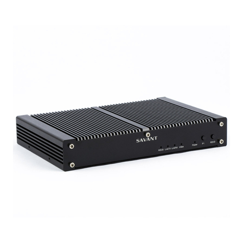
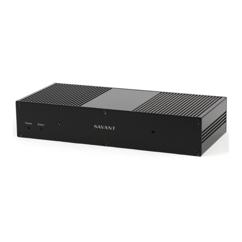
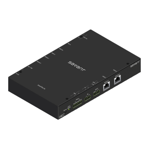
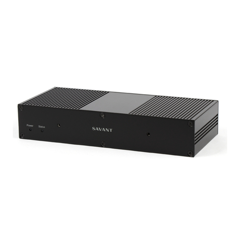
manuals.online logo
Brands
  1. Home
  2. •
  3. Brands
  4. •
  5. Savant
  6. •
  7. Receiver
  8. •
  9. Savant PAV-AOMBAL8C User manual

Savant PAV-AOMBAL8C User manual

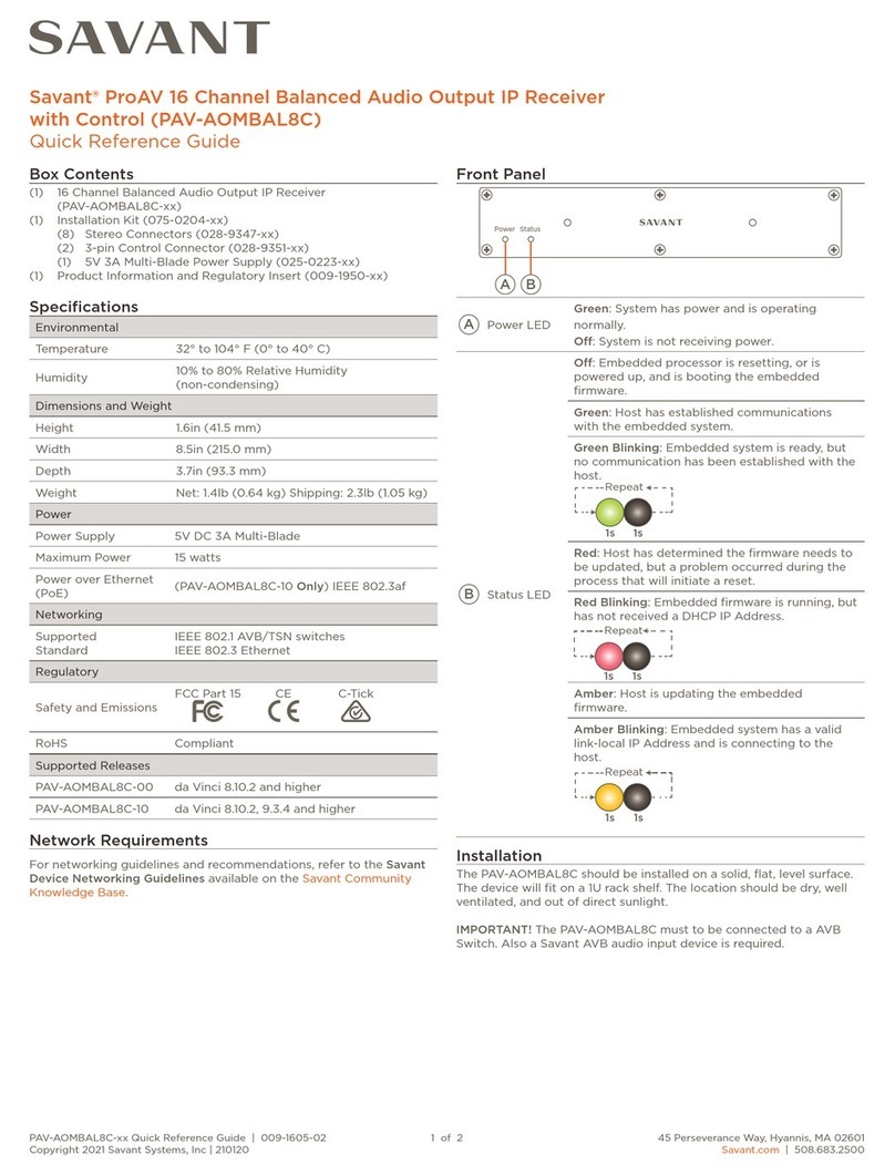
PAV-AOMBAL8C Quick Reference Guide | 009-1605-03 1 of 2 45 Perseverance Way, Hyannis, MA 02601
Copyright © 2022 Savant Systems, Inc. | 220527 Savant.com | 508.683.2500
Savant® ProAV 16 Channel Balanced Audio Output IP Receiver
with Control (PAV-AOMBAL8C) Quick Reference Guide
Box Contents
16 Channel Balanced Audio Output IP Receiver
(PAV-AOMBAL8C-xx)
(1) Installation Kit (075-0204-xx)
(8) Stereo Connectors (028-9347-xx)
(2) 3-pin Control Connector (028-9351-xx)
(1) 5V 3A Multi-Blade Power Supply (025-0223-xx)
(1) Product Information and Regulatory Insert (009-1950-xx)
Specifications
Environmental
Temperature 32° to 104° F (0° to 40° C)
Humidity 10% to 80% Relative Humidity (non-condensing)
Dimensions and Weight
Device Shipping
Height 1.6 in (4.15 cm) 2.2 in (5.59 cm)
Width 8.5 in (21.50 cm) 12 in (30.48 cm)
Depth 3.7 in (9.33 cm) 7.3 in (18.54 cm)
Weight 1.4 lb (0.64 kg) 2.3 lb (1.05 kg)
Rack Space 1U
Power
Power Supply 5V DC 3A Multi-Blade
Maximum Power 15 watts
Power over
Ethernet (PoE) IEEE 802.3af (PAV-AOMBAL8C-10 Only)
Networking
Supported
Standard
IEEE 802.1 AVB/TSN switches
IEEE 802.3 Ethernet
Regulatory
Safety and
Emissions
FCC Part 15 CE C-Tick UKCA
RoHS Compliant
Supported Releases
PAV-AOMBAL8C-00 da Vinci 8.10.2 and higher
PAV-AOMBAL8C-10 da Vinci 9.4.4 and higher
Network Requirements
For networking guidelines and recommendations, refer to the Savant
Device Networking Guidelines available on the Savant Community
Knowledge Base.
Expansion
Savant AVB devices can be connected in a single system, providing a
virtual audio switch that can be configured to suit almost any need.
The maximum number of devices varies based on the active da Vinci
runtime.
Front Panel
Power Status
A B
APower LED
Green: System has power and is operating
normally.
O: System is not receiving power.
BStatus LED
O: Embedded processor is resetting, or is
powered up, and is booting the embedded
firmware.
Green: Host has established communications
with the embedded system.
Green Blinking: Embedded system is ready, but
no communication has been established with
the host.
Red: Host has determined the firmware needs to
be updated, but a problem occurred during the
process that will initiate a reset.
Red Blinking: Embedded firmware is running,
but has not received a DHCP IP Address.
Amber: Host is updating the embedded
firmware.
Amber Blinking: Embedded system has a valid
link-local IP Address and is connecting to the
host.
Installation
The PAV-AOMBAL8C should be installed on a solid, flat, level surface.
The device will fit on a 1U rack shelf. The location should be dry, well
ventilated, and out of direct sunlight.
IMPORTANT! The PAV-AOMBAL8C must to be connected to a AVB
Switch. Also a Savant AVB audio input device is required.
Rack
The optional RMB-PAVAM2F-xx or RMB-PAVAM2-xx allows two
devices to be mounted side by side. This rack is compatible with all
standard 19-inch National Electrical Manufacturers Association (NEMA)
rack mounts.
The instructions below show the RMB-PAVAM2F-xx, both brackets
install the same way they just face dierent directions.
1. Align the bracket with the device’s mounting points.
2. Attach using the screws provided with the bracket.
PAV-AOMBAL8C Quick Reference Guide | 009-1605-03 2 of 2 45 Perseverance Way, Hyannis, MA 02601
Copyright © 2022 Savant Systems, Inc. | 220527 Savant.com | 508.683.2500
GPIO Wiring
General Purpose Input/Outputs (GPIO)
are binary I/O ports used on Savant
controllers to trigger an action within
the system. Events can control a device,
such as turning on an amplifier (output)
or detecting a state change for a device
(input) to perform a workflow. Pin 2 is
used for input or output depending on
configuration.
GPIO Pull Down Resistor (PD) Usage
GPIO pins are configured as inputs and are pulled high to 12V while the
host is booting up. To make the GPIO signal low during a host reboot
and/or a power cycle, attach the GPIO 1 pin to the PD pin. The PD pin
is a 1K ohm pull down resistor (to signal ground) which keeps the GPIO
output below 0.8V during processor boot times.
Stereo Wiring
The Balanced Audio Output
wiring uses included 5-pin
connectors. Each connector
has connections for Left and
Right channels and a ground.
NOTE: The Right and Left
channels share a ground
connection terminal.
Making Connections
1. Remove Power if power is
applied.
2. Pull to remove the terminal block
from the rear of the controller.
3. With a small flat bladed
screwdriver, turn the screws
on the top of the connector
counterclockwise until the
silver crimps in the front of the
connector opens enough to slide
the wire(s) into the square slots.
4. Strip back the insulation on each
of the wires ¼ inch. Insert the stripped wires into their proper ports.
Do not allow more than 1/8 inch of bare wire exposed.
5. Turn the screws clockwise until the screw tightens around the wire.
Tug on the wire a bit to verify the wires are installed securely.
6. Continue until all wires are installed.
7. Repeat steps 3 - 5 for any additional IR devices.
8. Plug terminal block back into the rear of the controller.
9. Reapply power.
NOTE: While not shown this
diagram, GPIO 2 follows the
same wiring as GPIO 1.
32
1
Pin 1 Ground
Pin 2 GPIO 1
Pin 3 Pull-Down Jumper 1
G 1 PD1
Rear Panel
-
+
USB
Reset
G PD2
2
2
L
GPIO
G PD1
1
1
-
Balanced Analog Audio Out
6
5
R
4
L R
--
G+
3
-
G
+ +
L R L
8
+
G
+
- - -
7
G
+M/N S/N UID
Ethernet
PoE
R
+
5VDC
A B C D E F
A
Reset
Resets the network settings of the device.
Hold Reset Button for 5 seconds while powered
on to clear network settings. Status LED will
rapidly blink red when reset is complete.
BUSB USB 2.0 Type A (reserved for future use).
C
GPIO
3-pin Control Connector
See GPIO Wiring for pinouts
GPIO Input: When configured as an input the
processor will look for a low (<0.8V DC) or a
high (>2.4V DC) state.
Minimum 0V DC / Maximum 12V DC.
GPIO Output: When configured as an output, the
port provides a binary output of 0-12V
DC 150mA max.
D
Balanced
Audio
Outputs
(8) Analog Stereo Balanced Line Output (Left &
Right). Direct Line Level 4.2-VRMS.
E
Ethernet
8-pin RJ-45 port
10/100/1000 Base-T auto-negotiating port with
Link/Activity LEDs.
Supports Power over Ethernet (PoE).
Supports Audio Video Bridging (AVB).
Activity LED
(Left)
Green Blinking: Activity (Rx/Tx).
O: No Activity.
Link LED
(Right)
Green Solid: Ethernet Link is
established.
O: Ethernet link is not
established.
FPower Input 5V DC 3A Multi-Blade
Additional Documentation
Refer to the following documents located on the Savant Customer
Community for additional information.
IP Audio Deployment Guide (009-1571-xx)
432
15
Pin Left -
Pin Left +
Pin Ground
Pin Right -
Pin Right +
1
2
3
4
5
< 1/8 inch
bare wire
exposed

Other manuals for PAV-AOMBAL8C

1

This manual suits for next models

1

Other Savant Receiver manuals

Savant PAV-VOM1C User manual

Savant

Savant PAV-VOM1C User manual

Savant PAV-VOMVP1F series User manual

Savant

Savant PAV-VOMVP1F series User manual

Savant FRC-P100 User manual

Savant

Savant FRC-P100 User manual

Savant PAV-AOMBAL8C User manual

Savant

Savant PAV-AOMBAL8C User manual

Savant IRX-LN01 User manual

Savant

Savant IRX-LN01 User manual

Savant PAV-VOMVP1F2 Series User manual

Savant

Savant PAV-VOMVP1F2 Series User manual

Savant PAV-VOM1CP2 User manual

Savant

Savant PAV-VOM1CP2 User manual

Savant PAV-AOM8C-10 User manual

Savant

Savant PAV-AOM8C-10 User manual

Savant HRX-4KVLC Series User manual

Savant

Savant HRX-4KVLC Series User manual

Savant ProAV 16 User manual

Savant

Savant ProAV 16 User manual

Savant PAV-AOM8C User manual

Savant

Savant PAV-AOM8C User manual

Savant HRX-SLN501 User manual

Savant

Savant HRX-SLN501 User manual

Popular Receiver manuals by other brands

Servonaut Zwo4E4 manual

Servonaut

Servonaut Zwo4E4 manual

Grundig STR-622 TWIN Service manual

Grundig

Grundig STR-622 TWIN Service manual

Yamaha RP-U200 Service manual

Yamaha

Yamaha RP-U200 Service manual

EMS 53-5414 Installation and programming instructions

EMS

EMS 53-5414 Installation and programming instructions

Yamaha RX-V395 owner's manual

Yamaha

Yamaha RX-V395 owner's manual

PCB Piezotronics HT356B11/NC Installation and operating manual

PCB Piezotronics

PCB Piezotronics HT356B11/NC Installation and operating manual

Furuno AA-45B Operator's manual

Furuno

Furuno AA-45B Operator's manual

Envoy EN2 DX2 user guide

Envoy

Envoy EN2 DX2 user guide

Maximum S-2000 FTA PVR user manual

Maximum

Maximum S-2000 FTA PVR user manual

Zaxcom QRX200 user manual

Zaxcom

Zaxcom QRX200 user manual

Ferguson FT-8100 HD user manual

Ferguson

Ferguson FT-8100 HD user manual

LG LH-T363SD owner's manual

LG

LG LH-T363SD owner's manual

LEGRAND 0 942 19 Description

LEGRAND

LEGRAND 0 942 19 Description

Beyerdynamic NE 900 D Cobra manual&nbsp;

Beyerdynamic

Beyerdynamic NE 900 D Cobra manual&nbsp;

Pioneer Elite VSX-49TX Service manual

Pioneer

Pioneer Elite VSX-49TX Service manual

R&S EB500 Getting started

R&S

R&S EB500 Getting started

Mocreo MOLINK 300 user guide

Mocreo

Mocreo MOLINK 300 user guide

Panasonic RF-P50 operating instructions

Panasonic

Panasonic RF-P50 operating instructions

manuals.online logo
manuals.online logoBrands
  • About & Mission
  • Contact us
  • Privacy Policy
  • Terms and Conditions

Copyright 2025 Manuals.Online. All Rights Reserved.