Sensors
MMS 22-PI2 / MMSK 22-PI2
Assembly and Operating Manual
SCHUNK GmbH & Co. Bahnhofstr. 106-134 info@schunk.com
Spann- und Greiftechnik D-74348 Lauffen/Neckar www.schunk.com
Tel. +
4
9
-7133-103
-0
Fax +
4
9
-7133-103
-2399
Product Description
The switching point can be adjusted after assembly of the sensor. As
a result, the sensor switches more exactly. A readjustment of the
sensor and several signal tests are no more necessary.
Moreover, the switching point and the tripping point can be
adjusted closer to each other than for the automatic mode.
At the same time the susceptibility to trouble and damage
increases.
In the mode of the lowest hysteresis, an error signal (such as jitter
or untimely switch off.) can be avoided, if the sensor is protected
against all types of disturbances (i.e. by shielding). Frequent types of
disturbances are change in temperature and electro-magnetic
influences.
Notes for Installation
The bending radius of the connection cable must be observed. The
Sensor cable and connector have to be fastened in a way that they
cannot be moved and clamped during operation.
After adjustment of the switching point, the surroundings should
not change magnetically any more.
The difference between teaching and working temperature should
not exceed 30 K.
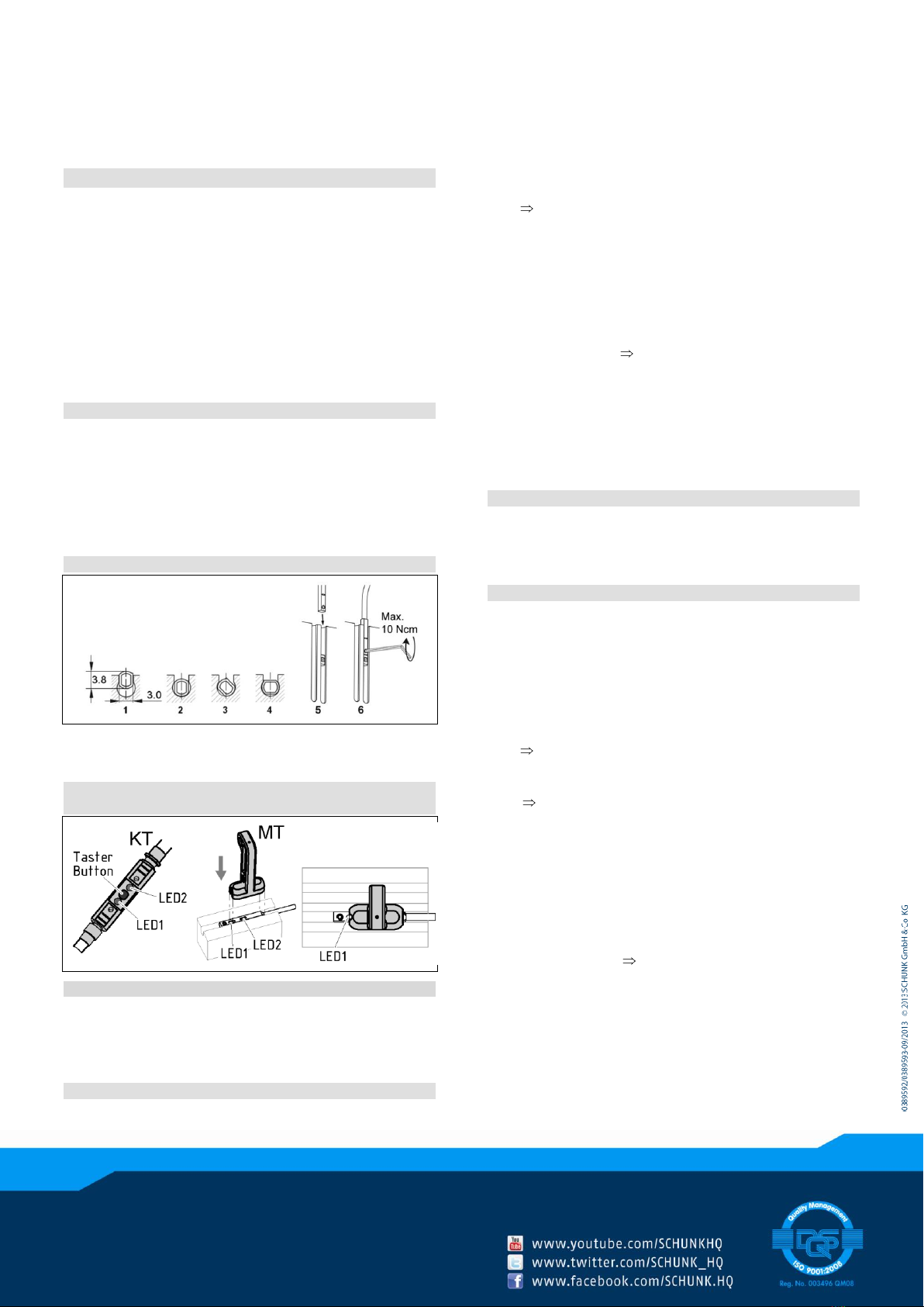
Installation of sensor
Turn in the sensor (1 to 4) or Push the sensor axially (5) into the slot
(The exact position is described in the manual of the respective
gripper).
Tracer at the Cable-Teach-Tool (KT) /
Attaching the Magnetic-Teach-Tool (MT)
Assembly without Teach mode
1. Connect the sensor to the power supply and push it into the
groove until the LED lights up.
2. Lock the position of the sensor with the enclosed tool.
Setting up the switching points - teach mode
1. Put the actuator into switching position (e.g. Gripper “Open”).
2. Place the MT for min. 2 seconds onto the sensor or press the
tracer at the KT for min. 2 seconds.
LED 1 is flashing after 2 seconds.
3. Remove the MT-Tool or release tracer at the KT
For switching point 1: Continue with step 4.
For switching point 2: Wait for 10 seconds, then continue with
step 4.
4. Place the MT-Tool for min. 0.3 seconds onto the sensor again,
then remove it or press button at the KT for min 0.3 seconds
and then release it.
5. Wait for 2 seconds LED 1 or LED 2 lights up continuously.
Notes
The setting procedure is cancelled after 30 sec. if the MT is not
inserted again or the button at the KT is not pressed.
LED 1 flashes 2 seconds long very fast, if the magnetic field is
too big or too small.
If there is a duplicate or unsuitable switching point, the sensor
should be moved by 2 mm and taught in again.
Assembly with teach mode-show optimal position
1. Put the actuator into switching position (e.g. Gripper “Open”).
2. Push the sensor in teach mode into the groove until the LED
flashes quickly.(see “Setting up the switching points - teach
mode”).
Hysteresis adjustment
The hysteresis adjustment is used for the manual adjustment of the
switch-off points (if necessary). In case that the hysteresis
automatically determined by the sensor should be too high or too
low after “the adjustment of the switching points”, you may correct
the value as follows.
1. Put the gripper to position “switch-off point”.
2. Place the MT-Tool at least min. 5 seconds onto the sensor or
press the button at the KT for 5 seconds.
The LED will flash up from the 2nd to the 5th second
and finally extinguishes.
3. Remove the MT-Tool immediately or release button at the KT.
LED 1 indicates through lighting the current
switching point, otherwise 1 LED is flashing.
For switching point 1: Continue with step 4.
For switching point 2: Wait for 10 seconds, until LED 2
indicates through lighting the current switching point.
Otherwise LED 2 is flashing.
4. Place the MT-Tool at least 0.3 seconds onto the sensor again
and then remove it immediately or press button at the KT for
at least 0.3 seconds.
5. Wait for 2 seconds After approx. 2 second the LED 1 will
light up twice if o.k., or if field is too high 2 sec. fast.
Notes
Depending on the magnetic field, a minimum and maximum
hysteresis will result from this.
If the switch-off point is taught in too far away from the
switch-on point, the original position will appear close to the
switching point. If that happens, please set the switch-off point
a bit closer.


