ES500 - 1 - 241002
Thank you for purchasing a Sealey Product. Manufactured to a high standard this product will, if used according to these instructions
and properly maintained, give you years of trouble free performance.
IMPORTANT:PLEASE READ THESE INSTRUCTIONS CAREFULLY. NOTE THE SAFE OPERATIONAL
REQUIREMENTS, WARNINGS AND CAUTIONS. USE THIS PRODUCT CORRECTLY AND WITH CARE FOR THE
PURPOSE FOR WHICH IT IS INTENDED. FAILURE TO DO SO MAY CAUSE DAMAGE AND/OR PERSONAL INJURY,
AND WILL INVALIDATE THE WARRANTY. PLEASE KEEP INSTRUCTIONS SAFE FOR FUTURE USE.
Instructions For:
UNIVERSAL ENGINE SUPPORT
Model: ES500
3Ensure that the engine support is in good working order. Take action for immediate repair or replacement of
damaged parts. Use genuine parts only. The use of unauthorised parts may be dangerous and will invalidate
the warranty.
3Locate the vehicle in a suitable, well lit work area.
3Keep work area clean and tidy and free from unrelated materials.
3Ensure the vehicle handbrake is engaged and the engine/motor is switched off.
3Ensure all non-essential persons keep a safe distance whilst the engine support is in use.
7DO NOT use the engine support if damaged.
7DO NOT allow untrained persons to operate the engine support.
7DO NOT use the engine support for purposes other than that for which it is designed.
7DO NOT exceed the rated capacity of the engine support.
1. SAFETY INSTRUCTIONS
2. INTRODUCTION & SPECIFICATION
2.1. The ES500 engine support is designed to support and
accurately position engines during maintenance
operations such as replacing anti-vibration mountings
and certain body panels. Also used as an aid for the
removal of gearboxes and transmissions. Beam is
supported on 4 rubber feet and fine-lift control obtained
by using a screw mechanism. Supplied with a short
length of chain.
4. OPERATING INSTRUCTIONS
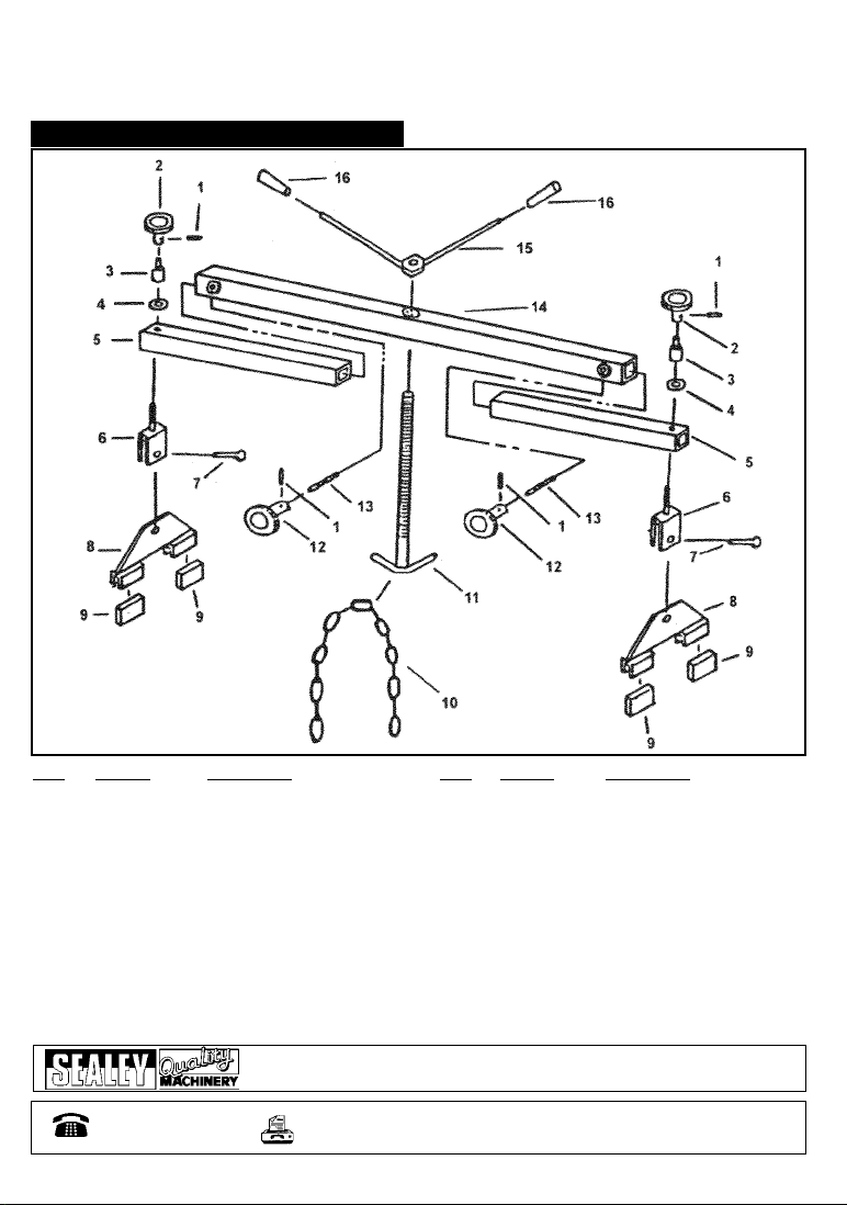
3. ASSEMBLY INSTRUCTIONS
Note: Numbers in brackets refer to item numbers shown in the parts diagram.
3.1. Insert the telescopic beam (5) into the beam (14) and secure using the grip (12).
3.2. Remove the grip (2) and washer (4) from the standing block (6), pass the threaded section of the standing
block through the hole in the telescopic beam (5) and secure using the washer and grip.
3.3. Remove the screw (7) from the standing block (6), insert the standing platform assembly (8) and secure
using the screw.
3.4. Repeat paragraphs 3.1 to 3.3 at the other end of the beam (14).
3.5. Slot the threaded section of the adjustable screw (11) up through the centre hole in the beam (14), fit the
and secure using the operating clamp assembly (15).
3.6. The engine support is now ready for use.
Note: Ensure all grips and nuts are tightened before applying a load.
Note: Numbers in brackets refer to item numbers shown in the parts diagram.
4.1. Ensure the adjustable screw (11) is wound to its highest position to prevent
damage whilst locating the engine support over an engine bay.
4.1. Ensure the grips (2 & 12) are loose and locate the rubber blocks (9) in the
gutters of the vehicles front wing panels or close to the suspension strut towers.
4.2. Attach the ends of the chain to the lifting brackets on the engine. Note: Refer
to manufacturers handbook to identify lifting brackets.
4.3. Lower the adjustable screw and hook the chain around the hook as shown in fig.1
2.2. Maximum Capacity . . . . . . . . . .500kg Minimum Width . . . . . . . . . . . .1020mm
Maximum Width . . . . . . . . . .1600mm Screw Travel . . . . . . . . . . . . . . .350mm
Fig. 1
ES500 - 1 - 241002
Thank you for purchasing a Sealey Product. Manufactured to a high standard this product will, if used according to these instructions
and properly maintained, give you years of trouble free performance.
IMPORTANT:PLEASE READ THESE INSTRUCTIONS CAREFULLY. NOTE THE SAFE OPERATIONAL
REQUIREMENTS, WARNINGS AND CAUTIONS. USE THIS PRODUCT CORRECTLY AND WITH CARE FOR THE
PURPOSE FOR WHICH IT IS INTENDED. FAILURE TO DO SO MAY CAUSE DAMAGE AND/OR PERSONAL INJURY,
AND WILL INVALIDATE THE WARRANTY. PLEASE KEEP INSTRUCTIONS SAFE FOR FUTURE USE.
Instructions For:
UNIVERSAL ENGINE SUPPORT
Model: ES500
3Ensure that the engine support is in good working order. Take action for immediate repair or replacement of
damaged parts. Use genuine parts only. The use of unauthorised parts may be dangerous and will invalidate
the warranty.
3Locate the vehicle in a suitable, well lit work area.
3Keep work area clean and tidy and free from unrelated materials.
3Ensure the vehicle handbrake is engaged and the engine/motor is switched off.
3Ensure all non-essential persons keep a safe distance whilst the engine support is in use.
7DO NOT use the engine support if damaged.
7DO NOT allow untrained persons to operate the engine support.
7DO NOT use the engine support for purposes other than that for which it is designed.
7DO NOT exceed the rated capacity of the engine support.
1. SAFETY INSTRUCTIONS
2. INTRODUCTION & SPECIFICATION
2.1. The ES500 engine support is designed to support and
accurately position engines during maintenance
operations such as replacing anti-vibration mountings
and certain body panels. Also used as an aid for the
removal of gearboxes and transmissions. Beam is
supported on 4 rubber feet and fine-lift control obtained
by using a screw mechanism. Supplied with a short
length of chain.
4. OPERATING INSTRUCTIONS
3. ASSEMBLY INSTRUCTIONS
Note: Numbers in brackets refer to item numbers shown in the parts diagram.
3.1. Insert the telescopic beam (5) into the beam (14) and secure using the grip (12).
3.2. Remove the grip (2) and washer (4) from the standing block (6), pass the threaded section of the standing
block through the hole in the telescopic beam (5) and secure using the washer and grip.
3.3. Remove the screw (7) from the standing block (6), insert the standing platform assembly (8) and secure
using the screw.
3.4. Repeat paragraphs 3.1 to 3.3 at the other end of the beam (14).
3.5. Slot the threaded section of the adjustable screw (11) up through the centre hole in the beam (14), fit the
and secure using the operating clamp assembly (15).
3.6. The engine support is now ready for use.
Note: Ensure all grips and nuts are tightened before applying a load.
Note: Numbers in brackets refer to item numbers shown in the parts diagram.
4.1. Ensure the adjustable screw (11) is wound to its highest position to prevent
damage whilst locating the engine support over an engine bay.
4.1. Ensure the grips (2 & 12) are loose and locate the rubber blocks (9) in the
gutters of the vehicles front wing panels or close to the suspension strut towers.
4.2. Attach the ends of the chain to the lifting brackets on the engine. Note: Refer
to manufacturers handbook to identify lifting brackets.
4.3. Lower the adjustable screw and hook the chain around the hook as shown in fig.1
2.2. Maximum Capacity . . . . . . . . . .500kg Minimum Width . . . . . . . . . . . .1020mm
Maximum Width . . . . . . . . . .1600mm Screw Travel . . . . . . . . . . . . . . .350mm
Fig. 1