Page 3Page 2
Electric Deadbolt Installation Manual Electric Deadbolt Installation Manual
SECO-LARM U.S.A., Inc. SECO-LARM U.S.A., Inc.
*
{
Installation
1. Determine where the deadbolt will be mounted (see fig. 1).
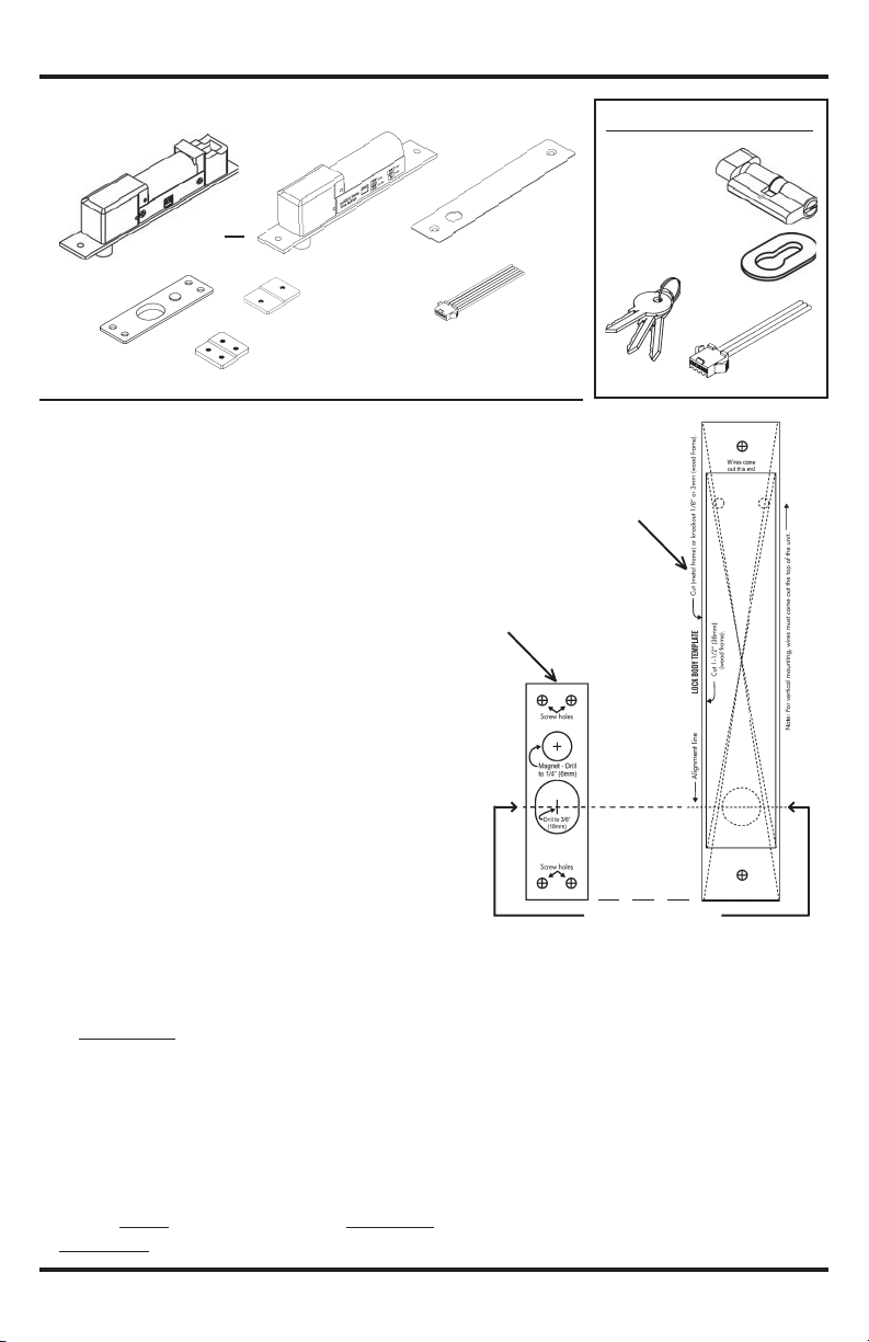
2. Tape the templates to the door frame and door (see fig. 3)
A. Align the templates so that the deadbolt of the lock body template
is centered on the deadbolt hole of the strike plate template.
B. Make sure to leave enough room at the ends of the lock body
and strike plate templates for mounting the mounting tabs.
3. Door frame cut (see fig. 4)
A. Cut out the space for the lock body.
B. Test the fit. The SD-977A-DQ/SD-997BQ lock body should
fit snugly inside the space.
C. Drill two 5mm screw holes as shown on the
template.
4. Door cut and mount. (see fig. 4)
A. For wood doors:
1) Use a chisel to knock out a 3mm (1/8-inch) deep space as
shown on the template.
2) Drill the magnet hole, 12mm (1/2”) wide by 6mm (1/4”) deep.
3) Use four wood screws to mount the strike plate in the
chiseled space. The magnet should fit in the magnet hole.
4) Use a drill to drill out the deadbolt hole to a depth of 16mm (5/8”).
B. For hollow metal doors:
1) Cut out the space for the strike plate.
2) Drill two screw holes for each of the two mounting tabs.
3) Use screws to fix the mounting tabs inside the hollow metal door.
4) Use screws to fix the strike plate to the mounting tabs.
5. Door jamb cut and mount (see fig. 4)
A. Cut out the space for the face of the lock body.
B. Drill one 5mm hole for each of the two mounting tabs.
C. Use screws to fix the mounting tabs inside the door jamb.
D.
SD-997A-DQ only: Insert the lock/unlock cylinder (see fig. 5).
E. Connect the wires, and insulate them (see fig. 7):
1) Red – Power input (+)
2) Brown – Power input (-)
3) Orange – Control wire (ground to release bolt)
4) Green – Door monitor, COM
5) Yellow – Door monitor, N.C. (active when door closed)
6) Blue – Door monitor, N.O. (active when door open)
IMPORTANT – Correct polarity of the red and brown
wires is critical. If you reverse polarity, the solenoid
will burn out!
Max. 50mm Door frame
Door
SD-997A-DQ
only*
*See separate
template.
F. Set the door lock delay timer (see fig. 8). This is the
time it takes the deadbolt to automatically lock after
the door is closed.
NOTE: The deadbolt automatically relocks 4 seconds after
an optional external push button (egress button) is
pressed, if the door was not opened.
The lock body has a sensor mechanism wherein it can
detect if the strike plate is in close proximity (such as
when the door is closed). If the door was closed but
somehow the strike plate was not aligned properly, the
door monitor indicator may indicate that the door is
Fig. 8 - Setting Door Lock Delay Timer
SD-997BQ
SD-997A-DQ
closed but the deadbolt remains unlock. During this time the
lock body may attempt multiple times to lock the door and if it
fails, it will stop to prevent the solenoid from burning out.
However if the lock body and the strike plate are too far
apart, the lock body will not attempt to lock the door and the
deadbolt will not throw out.
IMPORTANT – The lock body and strike plate must be
properly aligned and next to each other in order for the
product to function properly.
G.
Pull the vinyl covering off the faceplate, and place the faceplate
over the face of the lock body. Use screws to fix the faceplate
and lock body to the mounting tabs.
Screw to secure
cylinder to lock body
IMPORTANT – Push all the wires into the door frame. If
space is a problem, cut away part of the dust catcher inside
the frame, or carefully chip away part of the drywall, being
careful not to damage the wall.
6. For SD-997A-DQ only (see figs. 5 and 6)
Because the SD-997A-DQ offers fail-secure operation, the door
locks if power to the unit is cut. For such a situation, a separate
manual lock/unlock cylinder is provided for manual operation.
A. Insert the cylinder as shown in Fig. 5, and secure it to the
lock body with the provided long screw. Turning the key or
the manual knob will unlock the SD-997A-DQ manually.
B. Two separate templates are included for drilling holes in the
door frame for the key and manual knob.
C. A separate 3-pin connector for the SD-997A-DQ can be
connected to an alarm panel or annunciator to alert when
the door is locked or unlocked.
Fig. 2 - What’s Included:
SD-997A-DQ SD-997BQ
Strike
Plate x 1
Mounting tabs
(large) x 2
Mounting tabs
(small) x 2 •Templates x 4
•Mounting screws
6-Pin
connector x 1
Faceplate x 1
Lock body x 1
or
SD-997A-DQ Also Includes:
Manual
lock/unlock
cylinder x 1
Oval cylinder
plate x 2
Keys x 3
3-Pin
connector x 1
Fig. 6 - Installation of Manual Lock/Unlock Cylinder (SD-997A-DQ only):
Fig. 4 - Door and Frame Cuts
Installation at top of door
Installation at side of door
Drill hole
for lock Drill hole for lock
Drill hole
for lock Drill hole for lock
Line up these marks
Strike plate template
Lock body template
Fig. 3 - Aligning
Note:
If cylinder is used,
max. depth of door
frame is 50mm.
Fig. 5 - Manual Lock/Unlock Cylinder
(SD-997A-DQ only):
Card reader
or keypad
Orange
Brown wire
Red wire
SD-997A-DQ/SD-997BQ
See fig. 8
COM
N.C.
N.O.
Green wire - door monitor, COM
Yellow wire- door monitor, N.C.(active when door closed)
Blue wire - door monitor,N.O. (active when door open)
Push
button
12VDC
only
1Amp
Purple wire - active if door is locked (N.C.)
Gray wire - manual lock/unlock (COM)
Black wire - active if door is unlocked (N.O.)
For
SD-997A-DQ
only
{
Fig. 7 - Wiring
IMPORTANT – Do not cut wires before the plug as warranty
will be voided.


