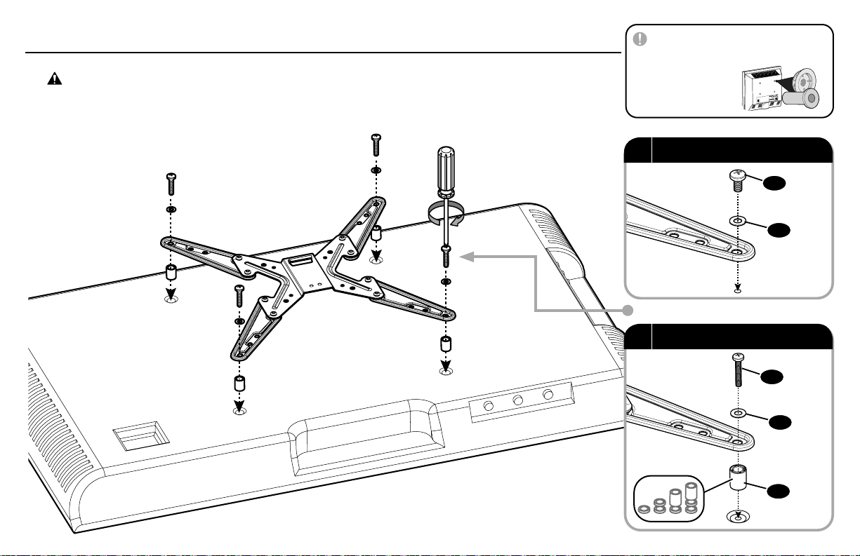
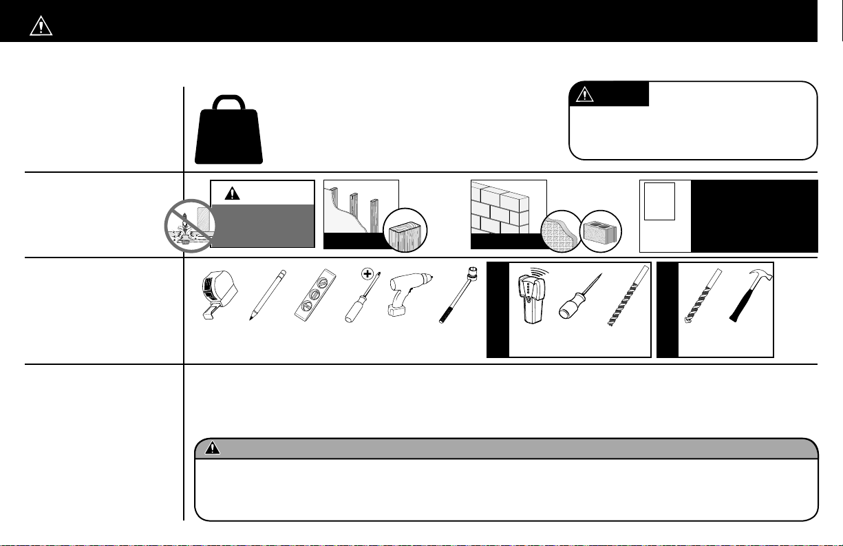
Secura QMF320-B2 User manual

Texto en español, página 20 Deutscher Text Seiten 24 Svensk text sida 28
中文文字说明请参见第 34 页
Texte français page 22 Nederlandse tekst op pagina 26
Русский текст: стр. 30
日本語は 32 ページ
WE’RE HERE TO HELP
Our install experts are
standing by to help.
Call us at:
US: +1 (800) 359-5520
EMEA: +31 (0) 495 580 852
UK: +44 (0) 800 056 2853
Get it right the first time.
HeightFinder™ shows
you where to drill.
Check it out at:
san.us/3021
Want to watch a video
that shows how easy this
DIY project will be?
Watch it now at:
san.us/3018
QMF320-B2
Full-Motion
TV Wall Mount
INSTRUCTION MANUAL

2
60 lbs.
(27.2 kg)
CAUTION:IMPORTANT SAFETY INSTRUCTIONS — PLEASE READ ENTIRE MANUAL PRIOR TO USE —SAVE THESE INSTRUCTIONS
Before getting started, let’s make sure this mount is perfect for you!
Does your TV
(including accessories)
weigh MORE than
60 lbs. (27.2 kg)?
Please read through these instructions completely to be sure you’re comfortable with this easy install process.
Also check your TV owner’s manual to see if there are any special requirements for mounting your TV.
If you do not understand these instructions or have doubts about the safety of the installation, assembly or use of this product,
contact Customer Service: US: +1 (800) 359-5520 | EMEA: +31 (0) 495 580 852 | UK: +44 (0) 800 056 2853.
Do you have
all the tools
needed?
1
2
3
4
What is your
wall made of?
Ready to begin?
CAUTION: Avoid potential personal injury or property damage!
Wood Stud Install
Concrete Install
Tape
Measure Pencil Level Screw
driver Electric
Drill Socket
Wrench Stud
Finder Awl Wood Drill
Bit Masonry
Drill Bit Hammer
3/8 in.
(10 mm)
1/2 in.
(13 mm) 7/32 in.
(5.5 mm)
Solid concrete or
concrete block?
Perfect!
Drywall with
wood studs?
Perfect! Unsure?
Contact customer service:
US: +1 (800) 359-5520
P: +31 (0) 495 580 852
UK: +44 (0) 800 056 2853
?
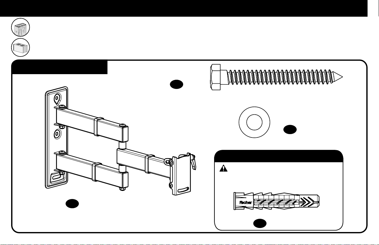
●This product is designed for use in wood stud, solid concrete, and concrete block walls - DO NOT install into drywall alone
●The wall must be capable of supporting five times the weight of the TV and mount combined
●Do not use this product for any purpose not explicitly specified by manufacturer
●Manufacturer is not responsible for damage or injury caused by incorrect assembly or use
No?Perfect – you may continue.
Yes?This mount is NOT compatible.
Visit secura-av.com or call US: +1 (800) 359-5520 | EMEA: +31 (0)
495 580 852 | UK: +44 (0) 800 056 2853 to find a compatible mount.
CAUTION:
DO NOT install
into drywall alone
CAUTION: DO NOT exceed the maximum weight
indicated. This mounting system is intended for use only with
the maximum weights indicated. Use with products heavier
than the maximum weights indicated may result in collapse of
the mount and its accessories, causing possible injury.

3
15.75in
400mm
MAX
15.75in
400mm
MAX
8.35in
212mm
1.57in
40mm
OFFSET FROM
CENTER
DETCARTERWEIVEDISDETCARTER-WEIVPOTTNUOMDELBMESSAYLLUF
SIDE VIEW - EXTENDED
3-D
TOP VIEW - EXTENDEDWALL PLATE
TV INTERFACE
19.43in
493.5mm
100mm
MIN
3.94in
3.94in
100mm
MIN
80mm3.15in
10.31in
262mm
SIMULATED 58"
FLAT SCREEN TV
435.6mm17.15in
17.15in
435.6mm
2.66in
ARMS
67.5mm
WITHOUT
EXTENSION
2.89in
73.5mm
WITH
EXTENSION
ARMS
45deg
45deg
5deg
15deg
Dimensions

4
STEP 1 Parts and Hardware
4 mm
M6 x 8 mm
5/16 x 2¾ in.
5/16 in.
Fischer UX10 x 60R
M8 x 25mm M8 x 50mm
M4 x 12mm
M6 x 12mm
M8 x 16mm
M4 x 35mm
M6 x 35mm
M8 x 35mm
2.5mm
M4 / M5
M6 / M8 22mm
NOTE: Not all hardware included will be used.
WARNING: This product contains small items that could be a choking hazard if swallowed.
Before starting assembly, verify all parts are included and undamaged. If any parts are missing or damaged, do not return the damaged item to your dealer; contact
Customer Service. Never use damaged parts!
STEP 1 Attach Faceplate to TV
TV Screws
(qty. 4 each) [Only one size fits your TV]
Washers Spacers [If necessary]
030201
M6/M8
M4 M4/M6/M8M4
M6
M8
(qty. 4)
(qty. 4)
(qty. 8)
(qty. 4)

5
4 mm
M6 x 8 mm
5/16 x 2¾ in.
5/16 in.
Fischer UX10 x 60R
M8 x 25mm M8 x 50mm
M4 x 12mm
M6 x 12mm
M8 x 16mm
M4 x 35mm
M6 x 35mm
M8 x 35mm
2.5mm
M4 / M5
M6 / M8 22mm
STEP 1 Parts and Hardware (continued)
04
05
06
08
09
07
(qty. 1)
(qty. 1)
(qty. 2) (qty. 2)
(qty. 1)
(qty. 8)
A
B
Wallplate and Arm
Faceplate
(attached)
Extender Brackets
Extender Screw
Hex Key

6
mm cm inches ≈
100 10 4
130 13 5⅛
200 20 7⅞
300 30 11 ¾
340 34 13 ¾
400 40 15 ¾
NOTE: Save screws
[S]
for use in Step 3.
1.1 Remove Faceplate from Arm
cm
inches
1.2 Measure TV hole pattern
05
05
04
04
[S]
[S]

7
400 mm
(15 ¾ in.)
340 mm
(13 ⅜ in.)
300 mm
(11 ¾ in.)
300 mm
(11 ¾ in.)
340 mm
(13 ⅜ in.)
400 mm
(15 ¾ in.)
200 mm
(7 ⅞ in.)
200 mm
(7 ⅞ in.)
130 mm
(5 ⅛ in.)
130 mm
(5 ⅛ in.)
100 mm
(4 in.)
100 mm
(4 in.)
08
1.3 Determine Configuration
09
06 05
07
06
07

8
1.4 Select TV Screws
M4 M6 M8
01
CAUTION: Verify adequate thread engagementwith your screw/washer/
spacer combination AND TV bracket (STEP 1-5).
-Too short will not hold the TV. -Too long will damage the TV.
1.5 Spacers (if needed)
aLong Screw
Short Screw
Washer
Washer
Spacer
Bracket
Bracket
02
01
05 05
06 06
07 07
01
03
02
b

9
If your TV included inset spacers
or wall mount adapters,
use them
UNDER the
mount hardware.
02
03
02
01
01
1.6 Install Faceplate
aScrew and washer
bSpacer(s), screw and washer
CAUTION: Avoid potential personal injuries and property damage! DO NOT use power tools for this step.
Tighten the screws only enough to secure the TV bracket to the TV. DO NOT overtighten the screws.

10
4 mm
M6 x 8 mm
5/16 x 2¾ in.
5/16 in.
Fischer UX10 x 60R
M8 x 25mm M8 x 50mm
M4 x 12mm
M6 x 12mm
M8 x 16mm
M4 x 35mm
M6 x 35mm
M8 x 35mm
2.5mm
M4 / M5
M6 / M8 22mm
04
10
11
12
(qty. 1)
(qty. 2)
(qty. 2)
(qty. 2)
For concrete installations ONLY
CAUTION: Do not use in drywall or wood
STEP 2 Parts and Hardware
Wall Plate and Arm
Lag Screw
Lag Screw Washer
Concrete Anchor
STEP 2 Attach Wall Plate / Arm to Wall
For wood stud installations, follow STEP 2A on PAGE 11
For concrete installations, follow STEP 2B on PAGE 14

11
STEP 2A Wood Stud Option
1 2 3
CAUTION: Avoid potential personal injuries and property damage!
Max. 5/8 in. (16 mm)
Min. Wood Stud Size:
nominal 2 in. (51 mm)
actual 1 ½ in. (38 mm)
Min. Wood Stud Size:
nominal 4 in. (102 mm)
actual 3 ½ in. (89 mm)
•Drywall covering the wall must not exceed 5/8 in. (16 mm)
•Minimum wood stud size:
nominal 2 x 4 in. (51 x 102 mm) actual 1½ x 3½ in. (38 x 89 mm)
•Stud center must be verified

12
45
Note Orientation
2¾in. (70 mm)
7/32 in.
(5.5 mm)
04

13
6
10 11
10 11
Note Orientation
Go to STEP 3 on PAGE 16.
04
CAUTION: Avoid potential personal injury or property damage! Improper use could reduce the holding power of the lag screws 10 .
Tighten the lag screws 10 only until the washers 11 are pulled FIRMLY against the wall plate 04 . DO NOT over-tighten the lag screws 10 .

14
CAUTION: Avoid potential personal injuries and property damage!
STEP 2B Solid Concrete or Concrete Block Option
Min.
8 in.
(203 mm)
Min.
16 in.
(406 mm)
Min.
8 in.
(203 mm)
Min.
8 in.
(203 mm)
1
2
Note Orientation
3/8 in.
(10 mm)
3 in. (76 mm)
04
•Mount arm assembly 04 directly onto concrete surface (no wall covering)
•Minimum solid concrete thickness: 8 in. (203 mm)
•Minimum concrete block size: 8 x 8 x 16 in. (203 x 203 x 406 mm)
IMPORTANT: Never drill into the mortar between blocks.

15
34
10 11
10
11
Note Orientation
12
04
CAUTION: Avoid potential personal injury or property damage! Improper
use could reduce the holding power of the lag screws 10 .
Tighten the lag screws 10 only until the washers 11 are pulled FIRMLY
against the wall plate 04 . DO NOT over-tighten the lag screws 10 .

16
CAUTION: Avoid potential personal injury or property damage.
These
screws [S]
must be installed to secure the TV onto the arm 04 .
1 2
STEP 3 Attach TV to Wall Plate
HEAVY! You may need assistance with this step.
04
05
[S] 09
05
04
NOTE: Fully extend arms 04 to ensure enough slack in cables.
(from Step 1)

17
Adjustments
Your TV should adjust easily when moved, then stay in place.
If your TV is too loose or too tight, adjust the tilt tension knob
[T]
.
NOTE: Once your TV is in place, tighten the tilt tension knob
[T]
to prevent unwanted movement.
[T]
b
d
c
a
TILT

18
[S]
To adjust TV level, loosen screws [S] on the rear of the arm plate using hex key
09
, adjust level, and retighten to secure.
CAUTION: Avoid potential personal injury or property damage. These
screws [S]
must be installed to secure the TV onto the arm 04 .
09
04
LEVEL

19
6 mm
To adjust arm tension, use a 6 mm hex key (not included).
CAUTION: Avoid potential personal injury or property damage!
Do not remove the screws during adjustments.
HEAVY! You may need assistance with this step.
04
04
05
[S]
09
EXTEND
RETRACT
ONLY IF NECESSARY
REMOVE

20
¿Su televisor pesa más de 27.2 kg (60 lb) incluidos los accesorios?
No: ¡Perfecto!
Sí: Esta montura NO es compatible. Visite Secura-av.com o llame al número US: +1 (800) 359-5520
| EMEA: +31 (0) 495 580 852 | Reino Unido: +44 (0) 800 056 2853 para encontrar una montura compatible.
27.2 kg
(60 lb)
Dimensiones Consulte la página 3
PRECAUCIÓN:
NO lo instale en paredes
únicamente de yeso
PRECAUCIÓN: NO supere el peso máximo
indicado. Este sistema de montaje está diseñado únicamente
para ser utilizado con el peso máximo indicado. Si se utilizan
productos que superen el peso máximo indicado, el soporte y
sus accesorios podrían caerse y causar lesiones.
ESPAÑOL
INSTRUCCIONES IMPORTANTES DE SEGURIDAD:
GUARDE ESTAS INSTRUCCIONES Y LEA TODO EL MANUAL ANTES DE UTILIZAR ESTE PRODUCTO.
¿Preparado para empezar?
Lea atentamente estas instrucciones en su totalidad para asegurarse de que está familiarizado con el sencillo proceso de instalación. Consulte igualmente el manual de su televisor para conocer si existen
requisitos especiales para el montaje de su aparato.Si no entiende las instrucciones o si tiene dudas acerca de la seguridad de la instalación, el montaje o el uso del producto, póngase en contacto con el Servicio
de Atención al Cliente: US: +1 (800) 359-5520 | EMEA: +31 (0) 495 580 852 | Reino Unido: +44 (0) 800 056 2853..
PRECAUCIÓN: ¡Evite posibles lesiones personales y daños materiales!
●Este producto se ha diseñado para su uso en montantes de madera, hormigón macizo y paredes de bloques de hormigón: NO lo instale en paredes únicamente de yeso
●La pared debe ser capaz de soportar hasta cinco veces el peso combinado del televisor y la montura
●No utilice este producto para ningún otro propósito que no sea el explícitamente especificado por el fabricante
●El fabricante no se responsabiliza de ningún daño o lesión resultante del montaje incorrecto o el uso indebido
¡Antes de empezar, asegúrese de que este es el soporte adecuado para usted!
1
2
3
4
¿De qué está
hecha la
pared?
¿Tiene todas las herramientas necesarias?
Localizador de
montantes Punzón Lápiz Nivel Destorni-
llador Cinta
métrica Taladro
eléctrico Broca para
madera Broca para
mampostería Llave de vaso Martillo
13 mm
(1/2 pulg.)
5.5 mm
(7/32 pulg.) 10 mm
(3/8 pulg.)
¿Hormigón macizo o
bloque de hormigón?
¿Paneles de yeso
con montantes de
madera?
¡Perfecto! ¡Perfecto! ¿No está seguro?
Llame al Servicio de
Atención al Cliente:
US: +1 (800) 359-5520
EMEA: +31 (0) 495 580 852
Reino Unido: +44 (0) 800 056 2853
?
Table of contents
Languages:
Other Secura TV Mount manuals

Secura
Secura QSF210 User manual

Secura
Secura QLF210 User manual

Secura
Secura QLTK1 User manual

Secura
Secura QLL22 User manual

Secura
Secura QLL23 User manual

Secura
Secura QMF107 User manual

Secura
Secura QMF110-B2 User manual

Secura
Secura QLF425-B2 User manual

Secura
Secura QLF315-B2 User manual

Secura
Secura QSL22 User manual

Secura
Secura QMT35-B2 User manual

Secura
Secura QMT15 User manual

Secura
Secura QSF207 User manual

Secura
Secura QLF314-B2 User manual

Secura
Secura QLF418-B2 User manual

Secura
Secura QLL23 User manual

Secura
Secura QML22 User manual

Secura
Secura QST25 User manual

Secura
Secura QLF214 User manual

Secura
Secura QMT25 User manual