Sensear SM1P-Ex User manual

SM1P-
Ex
MANUAL
ENGLISH
IEC Controlled Document–modifications to this document
must follow IEC Document Control Procedures.
Document
Reference:
Revision: Date:
IECEx126
AA.10
Feb 20, 2023


IECEx126 SM1P Ex Manual rev 10.00
1
INTRODUCTION
The SM1P/PW/B/DP/XBT Ex Series of Headsets is a state-of-the-art
hearing protection (i.e., protects against harmful noise)
communication system that allows you to retain situational awareness
whilst remaining in full contact with your team via Short- Range
technology, as well as two-way radio or cellular device via Bluetooth®
or wired connection.
The product meets the following international standards for use in
explosive gas, dust, and mining environments. Check the product label
to identify the ratings applicable to the headset.
II 2G Ex ib IIC T4Gb(-20oC ≤Ta ≤+40oC)
II 2D
Ex ib
IIIC
T155
o
C Db (-20
o
C
≤
Ta ≤
+40
o
C)
I M2Ex ib I Mb(-20oC ≤ Ta ≤ +60oC)
Cl I, Div 1 Grp A-D, T4 (-20oC ≤Ta ≤+40oC)
Cl I, Zn1, AEx ibIIC T4Gb (-20oC ≤Ta ≤+40oC)
Cl I, Zn21, AEx ibIIICT155oCDb(-20oC ≤ Ta ≤+40oC)
Situational awareness is provided by processing technology and
environmental microphones mounted within the headset.
Connection through intrinsically safe communication devices is
enabled by the SRCK61xxCCxx or SRCK62xxCCxx cable assemblies
(available separately). Cable part numbers vary depending on the
communication device connector. Please consult Sensear’s website or
your communications supplier for the appropriate cable.
For language translated manuals and further information, please refer
to Sensear’s website.
English

IECEx126 SM1P Ex Manual rev 10.00
2
MAINTENANCE
AND
SAFETY
INSTRUCTIONS
The SM1P-Ex has been designed such that minimal user maintenance is
required. Only those parts listed on page 25 of this instruction manual
are user replaceable.
SPECIFIC CONDITIONS OF USE Potential Electrostatic hazard, clean with
damp cloth only.
WARNING The SM1P-Ex must not be disassembled. In the event of a
malfunction the unit should be switched off and returned to Sensear Pty
Ltd. The battery is not user replaceable; the SM1P-Ex must be returned
to Sensear for battery replacement. Substitution of components may
impair Intrinsic Safety.
WARNING Connection to the USB Connector located in the connector
compartment of the right-hand ear-cup is not permitted. The USB is for
service only.
WARNING The SM1P-Ex must not be charged in a hazardous area. The
battery shall only be charged when the equipment is in a safe area using
the class II charging supply via the jack socket on the left- hand ear cup;
the maximum permitted voltage at this charging input is Um = 6V.
WARNING Connection to the multi-pin Hirose connector of the SM1P-Ex
(wired version) shall only be done via an SRCK61xxCCxx SM1P-Ex
Intrinsically Safe interface cable. No direct connection to the multi-pin
Hirose connector is permitted.
English

IECEx126 SM1P Ex Manual rev 10.00
3
ENTITY PARAMETERS
The following entity parameters are for when SM1P-Ex is used with
SRCK61xxCCxx or SRCK62xxCCxx at the radio or intrinsically safe device end
oftheinterface cable.
Entity Parameter
Value
U
i
/Vmax
9V
C
i
0.09µF
L
i
0µH
Ii
2.22A
Pi
1.3W
English

IECEx126 SM1P Ex Manual rev 10.00
4
MARKINGS
The SM1P-Ex contains the following markings:
Hazardous Location Class and Group and Temperature Class
A scratch-resistant classification label is located at the top of the left-side ear
cup on the headset.
Product Model, Number Code, and Serial Number
A product model name, number and serial label are located at the top of the
right-side earcup on the headset.
An eight-digit product code followed by a unique eight-digit serial number
will be visible on the top of the outer cup and of the form:
MFP00PPPSSSSSSSS where ‘MFP00PPP;’ isthe product number and
‘SSSSSSSS’ is the serial number.
English
IECEx126 SM1P Ex Manual rev 10.00
5
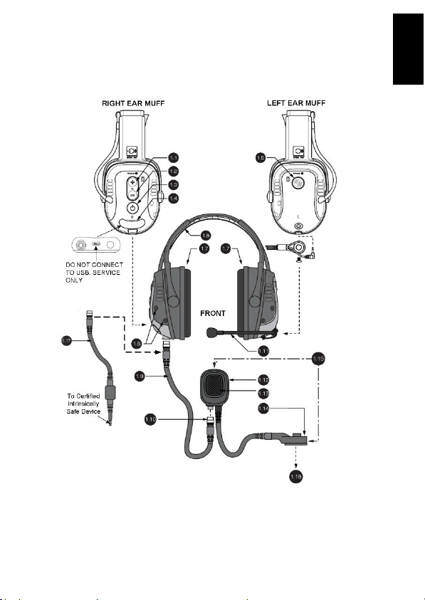
HEADSET ANATOMY
FIGURE 1
English
IECEx126 SM1P Ex Manual rev 10.00
6
# Description
1.1 Volume up button
1.2 Volume down button
1.3 Power button
1.4 Hatch cover, for programming and charging
1.5 Multi-function button (MFB)
1.6 Headband*
1.7 Ear cushions
1.8 Microphones
1.9 Headset cable
1.10 Headset connector
1.11
Boom microphone
Mount-M5 Hex screw
Connector- 2.5mm Audio jack
1.12 Inline PTT
1.13 Inline PTT button
1.14 Two-way radio connector (note, these will varydepending on
your two-way radio)
1.15 SRCK61xxCCxx cable assembly
1.16 To the two-way radio
1.17 SRCK62xxCCxx cable assembly
English
IECEx126 SM1P Ex Manual rev 10.00
7
WEARING
THE
HEADSET
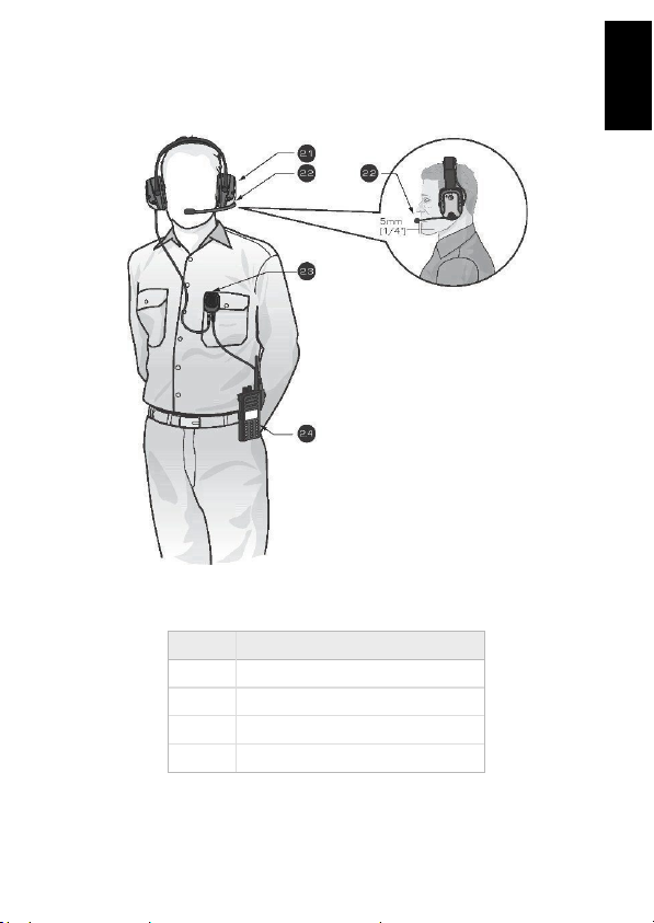
FIGURE
2
#
Description
2.1 Headset
2.2
Boom microphone
2.3
Inline PTT
2.4 Two-way radio
English

IECEx126 SM1P Ex Manual rev 10.00
8
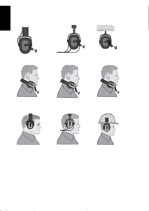
The SM1P-Ex headset is designed to be worn with the headset sealing
around the ears. Specific examples of how to fit the headset around the
ears are covered in the next three pages. The fit does alter slightly
depending on what style of brace is used - Headband, Behind-the-Neck,
or Helmet mounted.
The boom microphone should be placed approximately 5mm (1/4”) in
front of the mouth. Check to ensure the white dot or microphone label is
facing towards you. The orientation is essential as the microphone is
directional. If the microphone faces a different direction, this may lead to
a reduction in transmission quality.
The inline PTT has a rotatable clip behind it to allow it to attach to the
shirt / upper garment. The inline PTT must be connected to the two-way
radio using the multi-pin connector.
FITTING
THE
HEADSET
It is recommended that the wearer should ensure that:
•The earmuffs are fitted, adjusted, and maintained in accordance with
the manufacturer’s instructions
•The earmuffs are always worn inhigh noise conditions
If the above recommendations are not adhered to, the protection
afforded by the earmuffs will be severely impaired.
English
IECEx126 SM1P Ex Manual rev 10.00
9
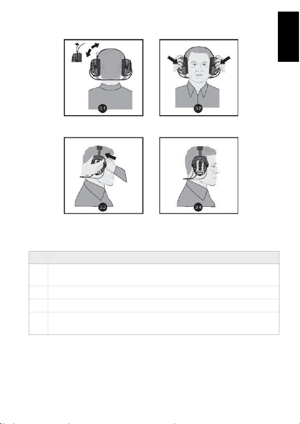
BEHIND-THE-NECK MOUNT FITTING INSTRUCTIONS
#
Description
3.1
Adjust Velcro strap so that the earmuff cups completely enclose the
ears
3.2
The earmuff cushions should seal firmly against the head
3.3
For best results, remove allhair from under the ear cushion
3.4 Noisereduction will be adversely affectedbyanything that breaks
the seal of the earmuff ear cushions
English
IECEx126 SM1P Ex Manual rev 10.00
10
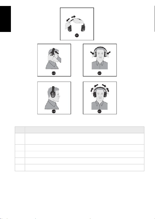
HEADBANDMOUNT FITTING INSTRUCTIONS
#
Description
4.1
Adjust the headband by pulling thecenter band out equally on both
sides
4.2
Ensure no hair is inside the muff ear cushions
4.3
Fit the earmuffs over the ears ensuring a tight fit around the ears
4.4
Ensure the muff surrounds the ears
4.5
Press down on the headband to obtain a snug and comfortable fit
English
IECEx126 SM1P Ex Manual rev 10.00
11
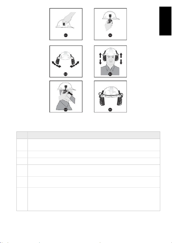
HELMETMOUNT FITTING INSTRUCTIONS
#
Description
5.1
Attach the adaptors to each side of the helmet by sliding them into
the slots
5.2
Attach the earmuffs by sliding into the adaptors
5.3
Ensure the earmuff is firmly attached by lifting the arm up and down
5.4
Place the helmet on the head and adjust by sliding the earmuffs up
and down
5.5
Earmuffs should seal firmly against the head. Forbest results, remove
hair from under the earmuffs.
5.6
Three adhesive mounts and ties are included to secure the earmuff
cable to the helmet. The mounts should be evenly spaced around
the rear outside of the helmet. Fit the tie through the mount. The
cable should feed through each tie and secured in place.
English
IECEx126 SM1P Ex Manual rev 10.00
12
DUAL PROTECTION FITTING INSTRUCTIONS
Locatethe ear buds inside the ear cup.
Place earmuff away from the ears while fitting the ear buds. Insert ear
tips following the ear tip fitting instructions on next page.
Place the earmuff back over the ears. Ensure the retractable, coiled
cable is fully located within the ear cup. Noise reduction will be
adversely affected by anything that breaks the seal of the earmuff
cushions.
English

IECEx126 SM1P Ex Manual rev 10.00
13
FOAM EARTIP FITTING INSTRUCTIONS
Ensure hands and
foam tips are clean
before insertion.
Place foam tip at an
angle to plastic
canal
Push the ear tip
firmly over the
plastic canal
Compress the foam to
form a cylindrical shape
being careful not to
crease the foam
Gently pull your ear up and backwards with one hand while inserting
the ear plug into the ear. Foam ear tips should be inserted within 5
seconds of compressing the foam. Make sure the plug seals well
into the ear canal. The ear tip should not protrude out of the ear
canal. If using foam ear tips hold the plug-in place for 20 seconds or
until the foam has fully expanded.
English
IECEx126 SM1P Ex Manual rev 10.00
14
OPERATING
THE
HEADSET
POWERON:
1. Press and release the “Power” button shown inFigure 1.
2. All the LEDs will turn on briefly, & an audible sound will be heard
through the headset.
3. The Green LED will flashat a normal rate as describedbelow.
POWER OFF:
1. Press and hold the “Power” button for 2 seconds.
2. All the LEDs will turn on briefly and an audible sound will be heard
through the headset as the headset powers off.
MODE:
When the headset is powered up, the unit is set into ‘ mode’.
By pressing the power button, this toggles ‘ mode’.
‘ mode’ allows full situational awareness of your surroundings in
addition to two-way radio, Bluetooth®, Short-Range, or face-to-face
communications.
•The power button toggles between Quiet mode and mode
•The volume control buttons can be used to raise or lower the
audio level of the mode
•**The default modeonpower up can be programmed using the
Sensear app
QUIET MODE:
By pressing the power button, this toggles ‘Quiet mode’. Quiet mode only
allows audio from communication devices to pass through the headset.
mode
Green LED, blink twice every 4 seconds
Quiet mode
Green LED, blink once every 4 seconds
English

IECEx126 SM1P Ex Manual rev 10.00
15
SETUP MODE:
Setup mode enables a limited number of settings to be changed
directly via the headset. This mode is separate from the normal
headset operating mode. Some options will not be available if the
product model does not support a feature or headset programming
has removed the setup mode option. For further setup, a programming
tablet will be required.
The options (with fully available feature set) are:
1. Short-Range – region
2. Short-Range –channel frequencies
3. FM Radio – enable/disable
4. VOX –feature assignment
5. VOX –trigger level
A short press and release of the power button will cycle through these
options when in setup mode.
Enter/Exit Setup Mode:
1. Headset is powered off
2. Hold Volume Up button
3. While holding Volume Up, Press & release Power button
4. Will hear “system setup”
5. Release Volume Up button
The headset needs to be powered down before it can be powered up
into its normal operating mode. Changes will be saved upon powering
off the headset from setup mode.
(short)
Cycle down through system setup options
(long)
Poweroff the headset.
English

IECEx126 SM1P Ex Manual rev 10.00
16
Changing Short-RangeRegion: Ensure you hear “Short-Range FM region”.
/ (short)
Increment/decrement through regions 1,
2 or 3.
Region EIRP
(uW)
Standards FM frequency range
(MHz)
1
8.02
AS/NZS 4268
88.1 –107.9
2
0.048
EN301357- 1
88.1 –107.9
3 0.012
FCC-15.239/ICRSS-
210 88.1 – 97.0
Set Short-Range FM Region
NOTE: Please use the FM frequency range allowed for your region as follows:
Region 1 for Australia/New Zealand
Region 2 for Europe
Region 3 for USA/Canada
English

IECEx126 SM1P Ex Manual rev 10.00
17
Changing Short-Range Frequencies: Ensure you hear “Short-Range FM
frequency”.
/ (short)
Change frequency:
up = increment 0.1MHz,
down=decrement0.1MHz
/ (long)
Change bank:
up = increment bank,
down=decrement bank
Note, frequency range is 88.1MHz to 107.9MHz (97.0MHz for region 3).
The frequency/bank last selected in the setup mode will be the
frequency/bank used when Short-Range is turned on in normal operating
mode.
Changing FM Radio Enable: Ensure you hear “FM radio”.
/ (short)
Toggle between “enable” and “disable”.
Changing VOX Assignment: Ensure you hear “VOX setup”.
/ (short)
Togglebetween “disable” and “Short-
Range”
Changing VOX TriggerLevel: Ensure you hear “VOX level”.
/ (short)
Cycle through “low”, “medium” and
“high” trigger levels
English

IECEx126 SM1P Ex Manual rev 10.00
18
“low” is the most sensitive/easiest to trigger VOX and “high” is the least
sensitive/hardest to trigger VOX.
COMMUNICATING
COMMUNICATING OVER TWO-WAYRADIO:
Only approved two-way radio cables (SRCK61xxCCxx) or adaptor cables
(SRCK62xxCCxx) containing a certified IS barrier may be used with SM1P-
Ex and SM1P-ExDP models.
To Transmit Over Two-Way Radio:
•
Press and hold the button located on the inline PTT
•
Release the inline PTT button to cease transmission
•
To change thevolume of the two-way radio communications, use
the two-way radio’s volume controls
NOTE:
•When the headset is powered off (and disconnected from the
inline PTT), the inline PTT button may not activate the two-
way radio. The PTT located on the two-way radio should be
used.
•When the headset is powered on, the two-way radio PTT may
not activate the two-way radio
•Audio will revert to radio when the headset connector is
disconnected (dependent on radio type and compatible SRCK
radio cable)
Two-Way Radio VOX: VOX can be used on VOX-enabled two-way radios.
Refer to the two-way radio documentation for the setup and use of the
VOX feature. To disable VOX, you can either turn VOX off on the two-way
radio or press the headset PTT once, depending on which two-way radio
model you use.
English
Other manuals for SM1P-Ex
1
Table of contents
Other Sensear Headset manuals

Sensear
Sensear SM1R User manual

Sensear
Sensear SM1R Manual

Sensear
Sensear SM1R User manual

Sensear
Sensear SM1P Ex Manual

Sensear
Sensear SM1P02 Ex User manual

Sensear
Sensear SM1P Owner's manual

Sensear
Sensear SM1R User manual

Sensear
Sensear SM1P Ex User manual

Sensear
Sensear SM1P Ex User manual

Sensear
Sensear SMART EARMUFF User manual

Sensear
Sensear SM1P User manual

Sensear
Sensear sp1r User manual

Sensear
Sensear sp1r User manual

Sensear
Sensear SM1P-Ex Manual

Sensear
Sensear SM1R User manual

Sensear
Sensear SmartGroup User manual

Sensear
Sensear SM1P User manual

Sensear
Sensear SM1 User manual

Sensear
Sensear SM1xSR User manual

Sensear
Sensear smartPlug SMPLUG Owner's manual


