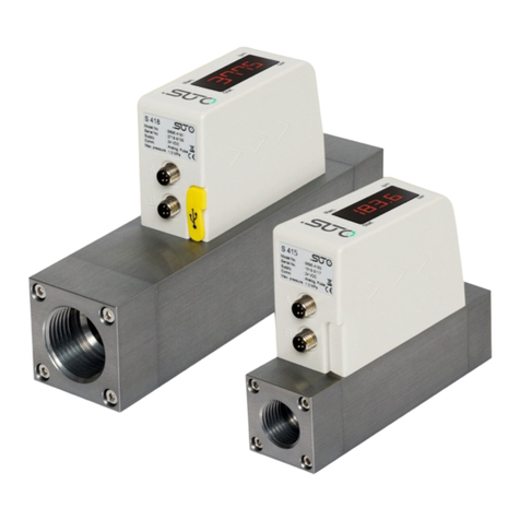
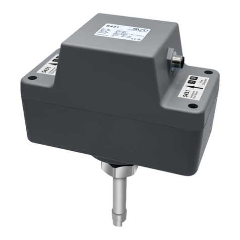
SUTO S462 Manual

English
Instruction and operation manual
S462
Ultrasonic flow meter

Dear Customer,
Thank you for choosing our product.
Before you start up the device please read this manual in full and
carefully observe instructions stated in this manual. The manufacturer
cannot be held liable for any damage that occurs as a result of non-
observance or non-compliance with this manual.
Should the device be tampered with in any manner other than a
procedure that is described and specified in the manual, the warranty is
void and the manufacturer is e empt from liability.
The device is destined e clusively for the described application.
SUTO offers no guarantee for the suitability for any other purpose.
SUTO is also not liable for consequential damage resulting from the
delivery, capability or use of this device.
2 S462

Table of Contents
1 Safety instructions.......................................................................4
2 Registered trademarks.................................................................6
3 Applications................................................................................7
4 Features.....................................................................................7
5 Technical Data............................................................................8
5.1 General......................................................................................8
5.2 Electrical Data.............................................................................8
5.3 Output signals.............................................................................8
5.4 Accuracy ....................................................................................9
5.5 Flow ranges.................................................................................9
6 Dimensions...............................................................................10
7 Scope of delivery.......................................................................11
8 Installation and connection.........................................................12
9 Electrical connection .................................................................13
10 Panel function.........................................................................13
11 Powering on............................................................................14
12 Keypad Functions.....................................................................14
13 Menu operations......................................................................15
13.1 Display menu...........................................................................15
13.2 Setup menu.............................................................................16
13.2.1 Setup Menu – Pipe parameter...............................................16
13.2.2 Setup Menu – System setting................................................17
13.2.3 Setup Menu – Calibration......................................................18
13.2.4 Setup Menu – Output...........................................................19
13.2.5 Setup Menu – History data....................................................19
14 Modbus communication protocol................................................20
15 Calibration .............................................................................23
16 Maintenance............................................................................23
17 Disposal or waste.....................................................................23
S462 3

1 Safety instructions
Please check if this instruction manual matches the
product type.
Please observe all notes and instructions indicated in this
manual. This manual contains essential information that must
be observed before and during installation, operation and
maintenance. Therefore this manual must be read carefully by the
technician as well as by the responsible user or qualified personnel.
This instruction manual must be available at the operation site of the
product at any time. In case of any obscurities or questions regarding
this manual or the product, please contact the manufacturer.
ARNING!
Voltage used for supply!
Any contact with energized parts of the product, may
lead to electrical shock which can lead to serious
injuries or even death!
•Consider all regulations for electrical installations.
•The system must be disconnected from any power supply during
maintenance work.
•Any electrical work on the system is only allowed by authorized
qualified personal.
ATTENTION!
Permitted operating parameters!
Observe the permitted operating parameters. Any
operation exceeding this parameters can lead to
malfunctions and might lead to damage on the
instrument or the system.
•Do not e ceed the permitted operating parameters.
•Make sure the product is operated in its permitted limitations.
Store and operate the product at the permitted temperature and
pressure.
•The product must be maintained and calibrated frequently, at least
annually.
4 S462

1 Safety instructions
General safety instructions
•It is not allowed to use the product in e plosive areas.
•Please observe the national regulations before/during installation
and operation.
Remarks
•It is not allowed to disassemble the product.
•Always use spanner to mount the product properly.
ATTENTION!
Measurement values can be affected by malfunction!
The product must be installed properly and
frequently maintained. Otherwise it might lead to
wrong measurement values, which can lead to
wrong results.
•Do not e ceed the ma imum operating temperature of the
transducer.
•Avoid condensation on the transducer element as this will affect
the accuracy enormously.
Storage and transportation
•Make sure that the transportation temperature of the device is
between -30 ... +70°C.
•For transportation it is recommended to use the packaging which
comes with the device.
•Please make sure that the storage temperature of the device is
between -30 ... +70°C.
•Avoid direct UV and solar radiation during storage.
•For the storage the humidity must be <95% with no condensation.
S462 5

2 Registered trademarks
SUTO®Registered trademark of SUTO iTEC
MODBUS®Registered trademark of the Modbus Organization,
Hopkinton, USA
HART®Registered trademark of the HART Communication
Foundation, Austin, USA
PROFIBUS® Registered trademark of the PROFIBUS User
Organization, Karlsruhe, Germany
Android™,
Google Play
Trademarks of Google LLC
6 S462

3 Applications
3 Applications
The S462 is an ultrasonic flow meter that is designed to measure the
flow and consumption of liquids within the permissible operating
conditions. S462 is using clamp-on technology that can be mounted
outside the pipe and brings flow measurement with benefits including
reduced installation costs, uninterrupted production, and no contact
with liquid to be measured.
The liquids that S462 can measure include the following:
•Cooling and heating water
•Drinking water
•Potable water
•De-ionized and de-mineralized water
•Sanitary liquid
•Purified water
•Other liquids on request
The default units are: Velocity in m/s, Volume flow in LPM and Total
Consumption in m3. Other units are available by configurations through
the optional display or the service kit.
The S462 flow meter is mainly used in industrial environment. It is not
developed to be used in e plosive areas. To use it in e plosive areas
please contact the manufacturer.
4 Features
•Uses the proven clamp-on transit-time correlation technique.
•Easy to install for permanent and temporary installations.
•High accuracy.
•Configurable physical units.
•Available in DN20, DN25, DN32, and DN40.
•Connectable via Modbus/RTU to displays and data loggers from
SUTO iTEC.
S462 7

5 Technical Data
5 Technical Data
5.1 General
Dimensions See dimensions for different models on page
10.
Weight 0.47…0.60 kg (depends on model)
Keypad Four keys
Display OLED, 128 64 pi el (31 16 mm)
Physical units Metric and imperial units are available
Consumption: m3, L, GAL
Flow: m3/h, m3/min, GAL/min
Velocity: m/s
Consumption counter Daily, monthly, and yearly totalizers
6 digits
Liquids / Medium Water, sea water, other liquids in request
Pipe Material Carbon steel, stainless steel, copper, PVC, PP,
PU
Case Material Housing: Aluminum alloy
Sensor: PEI
Display cover: PMMA
Key pad: F150
Environment Temp. 0 °C … 50 °C
Liquid Temp. 0 °C … 50 °C
Environment Humidity 0 … 95% relative humidity without
condensation
IP Grade IP65
5.2 Electrical Data
Power supply 20 … 28 VDC / 100 mA
Cable length 2 m
5.3 Output signals
Analog output 4 … 20mA, Ma imum load: 600 Ω
Communication RS485, Modbus RTU
8 S462

5 Technical Data
5.4 Accuracy
Measuring range 0.05 ... 5.0 m/s
Accuracy 1.5% o.RDG + 0.2% FS (0.5 … 5.0 m/s)
Repeatability 0.80%
Response time 2 s
5.5 Flow ranges
Model DN20 DN25 DN32 DN40
Pipe size
(mm)
Pipe OD 25...28 32...35 38...45 48...54
Pipe ID 20 25 32 40
NPS 3/4" 1" 1¼" 1½
Flow Range
(l/min)
0.05 m/s 0.9 1.5 2.4 3.8
0.5 m/s 9.42 14.7 24.1 37.7
5.0 m/s 94.2 147.2 241.2 377.0
S462 9

7 Scope of deli ery
7 Scope of delivery
Make sure that all components listed below are included in the product
package.
Any questions, please contact your representative as soon as
possible.
Qty Description Item no.
1 S462 Ultrasonic flow meter, including upper
brackets and lower brackets
S695 4621 (DN20)
S695 4622 (DN25)
S695 4623 (DN32)
S695 4624 (DN40)
1 2 m cable with an M12 connector included NA
4 Coupling pads A695 4620
1 Instruction manual NA
1 Calibration certificate NA
S462 11

8 Installation and connection
Follow the instructions below to install the flow meter onto the pipe.
Step 1. Clean the pipe to make
sure no dirt, paint, or any stains
on its surface. Add the coupling
pads onto the sensor surface.
Step 2. Place the flow meter with
the upper brackets (installed
together e -works) on the pipe.
Install the meter on the side of the
pipe instead of the top to avoid
bubbles effecting the measurement.
Step 3. Place the two base
brackets directly under the upper
brackets across the pipe. Finally,
tighten the screws on both ends.
Step 4. Connect the cable to the
M12 connector and then tighten
them up.
12 S462

9 Electrical connection
M12 connection pins
Pin 1 Pin 2 Pin 3 Pin 4 Pin 5
Signal DC+ RS 485B RS 485A DC- /
4...20 mA-
4...20 mA+
Color Brown White Blue Black Gray
Legend to pin assignment
DC+ Positive supply voltage
DC- Negative supply voltage
RS 485A Modbus/RTU data +
RS 485B Modbus/RTU data -
4...20 mA+ Positive 4 ... 20 mA signal
4...20 mA- Negative 4 ... 20 mA signal
10 Panel function
S462 13

11 Powering on
11 Powering on
After the flow meter is powered on, the self-diagnosis program starts to
run. The display will show the last selected main screen.
Signal Quality (SQ value)
Indicates the level of the signal detected using
the number from 0 … 99. 0 represents the
minimum signal detected and 99 represents the
ma imum signal. For a reliable measurement a
SQ value of >70 is required.
Adjust the transducer position repeatedly and
check the coupling pad frequently until the signal
quality detected is as strong as possible.
12 Keypad Functions
To switch between the Setting and the Display modes.
To return to the previous menu when in the Setting mode.
To scroll up and down the menu list.
When entering digits, press to move to the ne t digit.
Press to scroll the number from 0 to 9.
To confirm a selection.
14 S462

13 Menu operations
13 Menu operations
13.1 Display menu
This main screen shows Date, Time, Velocity and
Net Totalizer.
This main screen shows Signal Quality (SQ),
Time, Flow and Net Totalizer.
This main screen shows Signal Quality (SQ),
Time, Velocity, Flow and Net Totalizer.
This main screen shows the Run Time of the
instrument in hours and the current Daily,
Monthly and Yearly Consumption.
This main screen shows the Signal Quality, Time,
Flow and the Consumption since last power on.
S462 15

13 Menu operations
13.2 Setup menu
The Setup menu is used to do the configuration
of S462 after installation. These parameters are
important for proper operation of the
instrument.
Following options are available:
0. Pipe parameter
1. System setting
2. Calibration
3. Output setting
13.2.1 Setup Menu – Pipe parameter
Every installation requires pipe settings and fluid settings at least.
Following settings are done here:
•0: Outer diameter of pipe
•1: all thickness of pipe
•2: Material (PVC, Carbon steel, Steel, or
Copper)
•3: Fluid type (Water, Sea Water, oil,
others). For others the sonic velocity of the
fluid to be measured needs to be entered.
Note: The above four settings are crucial for an
accurate measurement.
16 S462

13 Menu operations
13.2.2 Setup Menu – System setting
The system settings have following options:
0. System Unit:Metric or Imperial units
1. Flow rate unit:m3/h, LPM, or GPM
2. Total unit:m3, L, or GAL
3. Totalizer RESET:To clear the consumption
counters to zero
4. Time set: To set the time. Generally, it is
unnecessary to modify date and time because the
system comes with a highly reliable perpetual
calendar chip.
5. System lock: To lock or unlock S462. Once the
system is locked, any modifications to the system
are prohibited, but parameters are readable. You
can “unlock” the system by entering your password.
If you forget your password, contact the
manufacturer.
6. System INFO: To display system information
consisting of the Serial number (SN) of the
electronics system. This S/N differs from the S/N
printed outside the instrument on the label. Both
S/N can be used for tracking.
7. Display Direction: Depending on the
installation it may required to swap the display
direction.
8. Damping: A damping factor can be entered to
stabilize the reading. Default is 3.
S462 17

13 Menu operations
13.2.3 Setup Menu – Calibration
The system settings have following options:
0. Scale factor: Refers to the ratio between “actual
value” and “reading value”. For example, when the
actual value is 2.00, and the meter displays 1.98 on
the screen, the scale factor reading is 2/1.98. The
default scale factor is factory calibrated and close
1.000.
1. 4-20mA CAL: Can be used to calibrate / adjust
the 4-20 mA output. Pressing the <Enter> selects
between 4 mA and 20 mA output. By using an amp-
meter the accuracy can be checked. If the reading is
not accurate it can be adjusted with the <arrow>
keys.
2. Set zero: Is used to make a zero flow calibration
or to reset the last calibration and bring it back to
factory setting. In order to make a zero calibration
there must not be any flow in the pipe!
Use the <arrow> keys to select between the 2 choices
and press <Enter> to activate. The calibration process
may take a few seconds.
3. Low flow cut: When the flow rate falls below the
low flow cutoff value, the flow indication is set to zero.
This function can prevent the flow meter from reading
the flow rate after a pump is shut down but there is
still liquid movement in the pipe, which will result in
totalization error.
Generally, 0.03m/s is recommended to enter as the
low flow cutoff point. The low flow cutoff value has no
relation to the measurement results once the velocity
increases over the low flow cutoff value.
4. Manual zero: When the zero point cannot be set
due to on-site working conditions, a zero point can be
manually set to force the zero point to be achieved
(this function is not commonly used).
18 S462

13 Menu operations
13.2.4 Setup Menu – Output
0. RS485 Setup:
0. Network addr: Is the device address within
the RS-485 network. Default is 001.
1. RS485 Baudrate: Available baudrates:
2400, 4800, 9600, 19200. Other parameters
are fi ed at 8 data bits, no parity, 1 stop bit.
1. 4-20 mA range: Is used to set the scaling of
the analog output to the desired flow rate in the
selected flow unit.
2. Alarm value: (not supported)
3. OCT output: (not supported)
4. OCT multiplier: (not supported)
13.2.5 Setup Menu – History data
0. By Day: lists the daily consumption of the past
63 days.
1. By Month: lists the daily consumption of the past
63 months.
2. By Year: lists the daily consumption of the past 9
years.
S462 19

14 Modbus communication protocol
Request from master:
Contents Slave
address
Function code Register
address
Number of
registers
Check
code
Size (bytes) 1 1 2 2 2
Data Range 0 01…0 F9 0 03 (read)
0 06 (write)
0 0000...0 FFFF 0 00...0 7D CRC
Response from slave:
Contents Slave
address
Function code Data size Data Check
code
Size (bytes) 1 1 1 2 N1) 2
Data Range 0 01…0 F9 0 03 (read)
0 06 (write)
2 N1) --- CRC 2)
Remarks:
1) N = number of registers requested
2) The CRC check code of this instrument is obtained by CRC-16-IBM (polynomial
X16 + X15 + X2 + 1, mask word 0 A001) cyclic redundancy algorithm. The low
byte of the check code is first, and the high byte is after.
Type of byte order: MID-LITTLE-ENDIAN:
Type of byte order Byte sequencing (HEX) Example
MID-LITTLE-ENDIAN C D A B 0 0A 11 42 C5
LITTLE-ENDIAN D C B A 0 11 0A C5 42
BIG-ENDIAN A B C D 0 42 C5 0A 11
20 S462
Table of contents
Other SUTO Measuring Instrument manuals