Shannon ABM-D 135 User manual

User’s Guide
English
Plastic bending machine
ABM-D 135

ABM-D 135
12-12-2018
-1-
Ruben Rapati
1USER’S GUIDE
Plastic bending machine
ABM-D 135
©2018 SHANNON BV. All rights reserved.
No part of this User's Guide may be photocopied, altered or
translated without prior written consent.
Information contained in this User's Guide is subject to change
without notice

ABM-D 135
12-12-2018
-2-
Ruben Rapati
2TECHNICAL DATA
type
ABM-D 135
Assembly
Control unit
Max.
4
Upper heating profiles
Under heating profiles
Max.
Max.
2
2
Pressure bars
2
Electrical
Control units
Voltage
220 –240 V AC
Power
500 VA (each up)
800 VA (each down)
Fuse
5 AT x1 (each)
Timer unit
Voltage
220 –240 V AC
Power
5VA
Fuse
2,5 AT x2
connection
CEE 7/4 16A 2P+A
Network connection
CEE 7/4 16A 2P+A
Network circuit breaker
Max. 16 A
Pneumatic
Air
Unlubricated clean dry air
Maximum
8 bar
Minimum
6 bar
Operating pressure
6 bar
Coupling
Quick action coupling
Mechanical
Gradation of stop
0 - 500 mm
dimensions
[LxWxH]
850 x 1.510 x 380 mm
weight
200 Kg
Functional
Bending width
1.350 mm
Sheet thickness
0,2 –1,0 mm (with foil bending profile)
1,0 –5,0 mm.
Ambient
Temperature
18-30 C
Humidity of the air
50-80 % (no condensed)
Miscellaneous
set of socket screws keys
1 set [1½, 3, 5 mm]
Spare fuse
2 x [6.3x32 2,5 AT]
4 x [6.3x32 5,0 AT]

ABM-D 135
12-12-2018
-3-
Ruben Rapati
3CONTENTS
2 Technical data 2
3 Contents 3
4 Introduction 4
5 Description of the machine 5
6 Safety instructions 6
7 Safety precautions 8
8 Legend 9
8.1 Summary 9
8.2 Air/Timer Unit 10
8.3 Timer Unit 10
8.4 Control Unit 11
9 Installation 12
9.1 Assembly 12
9.2 Connecting foot switch 12
9.3 Connecting compressed air 12
9.4 Connecting power 12
10 Operation 13
10.1 Preparation 13
10.2 Switching on machine and heating 13
10.3 Setting temperature 13
10.4 Setting cycle time 14
10.5 Foot switch 14
10.6 Setting air pressure 14
11 Adjustment 15
11.1 Safety precautions 15
11.2Pressure bar and upper heating profiles 15
11.3Upper heating profile height 15
11.4 Lower heating profile positioning 16
11.5Parallel Back Stop 16
11.6 Angular stop 16
12 Maintenance 17
12.1Safety precautions 17
12.2 Tensioning and changing Filament 17
12.3 Lubrication points 18
12.4 Profiles 18
12.5 Water separator 18
13 Fuses 19
Annexes 20
A Options 20
Accessoires 20
B Equipment 21
Service and warranty 22

ABM-D 135
12-12-2018
-4-
Ruben Rapati
4INTRODUCTION
Congratulations on purchasing Shannon’s plastic bending machine ABM-D 135. Read
this guide completely before installing and using the machine.
We want to keep in contact and to know how you find the ABM-D 135. We are
always willing to advise on the use of the machine and its accessories.
SHANNON BV
Turfschipper 11
2292 JC Wateringen
P.O. box 84
2290 AB WATERINGEN
the Netherlands (EC)
Tel: +31 (0)174-225240
Fax: +31 (0)174-225249
E-mail: [email protected]l
Website: www.shannon.nl

ABM-D 135
12-12-2018
-5-
Ruben Rapati
5DESCRIPTION OF THE MACHINE
The Shannon ABM-D 135 bending machine is an automatic machine for the production of large
series of items with a single or double bend for the plastic sheet processing industry.
The machine has 4 heating profiles (2 up and 2 down). The temperature of which can be
adjusted by electronic controls.
The heating profiles which are mounted in the pneumatically operated top frame is adjustable
in height in respect of the working surface.
The heating profiles which are mounted in the bottom frame have a heating wire that can be set
in height.
The workpiece can be heated from one or both sides. When used with foil bending profiles in
the top frame it can be heated by contact, making it possible to bend sheets under 1 mm
thickness.
The top frame is switched on independently of the control unit and is controlled by an
adjustable timer.
The heating, and cooling/turning time can be set with the same timer.
The working surface is made of scratch-resistant solid core material to support the plastic
sheet.
When heated, thermoplastics become so flexible that they can be shaped. When a plastic sheet
is heated to its softening point, it can be bent to any angle desired. The bending and cooling is
done by the machine.
The bending radius is determined by the width of the heated zone. The zone is determined by the
thickness of the material and the type of heating element.
When heated, thermoplastics become so flexible that they can be
shaped. When a plastic sheet is heated to its softening point in a
narrow zone, if can be bent to any angle desired.
The bending radius is determined by the width of the heated zone.
The zone is determined by the thickness of the material, the type of
heating element and the distance between the plastic and the
filament.
Every plastic has its specific softening point. By co-ordinating the
temperature, heated zone and heating time all kinds of
thermoplastic can be processed.
ABM-D 135
12-12-2018
-6-
Ruben Rapati
6SAFETY INSTRUCTIONS
To ensure safety when using the machine you should read this
User's Guide carefully and follow the safety instructions closely
Attention!
The machine contains a section where there is a risk of trapping.
Attention!
The machine contains parts, which are hot. Touching them will
cause burns.
Allow hot parts to cool sufficiently (at least 10 minutes) before
touching them.
Never touch the heating elements when the machine is in
operation.
Always wear close-fitting clothing.
Be particularly careful of sleeves and always tie back long hair.
Never leave objects on the working surface after a cycle of the
machine.
The machine may only be used for heating zones in flat plastic
sheet.
Any other use could lead to very hazardous situations or cause
damage to the machine!
The plastic sheets that have to be bent may never be thicker than
5 mm.
Before commissioning and servicing always check the connection
cable and plug for defects.

ABM-D 135
12-12-2018
-7-
Ruben Rapati
When servicing switch off the machine and remove the plug from
the socket.
Before use always check that all the pressure bars and heating
elements in the top frame are firmly attached.
Never operate the machine if anyone is standing close behind or
beside it.
Never introduce objects or material into the machine from the
rear.
Never leave the machine unattended without switching it off.

ABM-D 135
12-12-2018
-8-
Ruben Rapati
7SAFETY PRECAUTIONS
EMERGENCY STOP
There are 2 emergency stops button (C) at the front of the machine, which can be
reached by the operator from the normal working position(s).
Pressing the emergency stop button switches off the machine and the top frame lifts
up. The button remains pushed in.
Resetting of the emergency button comes to pass by turning the button to the right.
The machine is ready to use again.
ONLY USE THE EMERGENCY STOP BUTTON WHEN:
oRisk of trapped limbs.
oDefects in the timer, so the machine fails to open after the pre-set time.
oAn outbreak of fire or situations involving a risk of fire.
oAny situation that might present a risk to people or animals.
oAny other situation, that might present a risk or cause, damage to the
machine and/or objects.
ABM-D 135
12-12-2018
-9-
Ruben Rapati
8LEGENDA
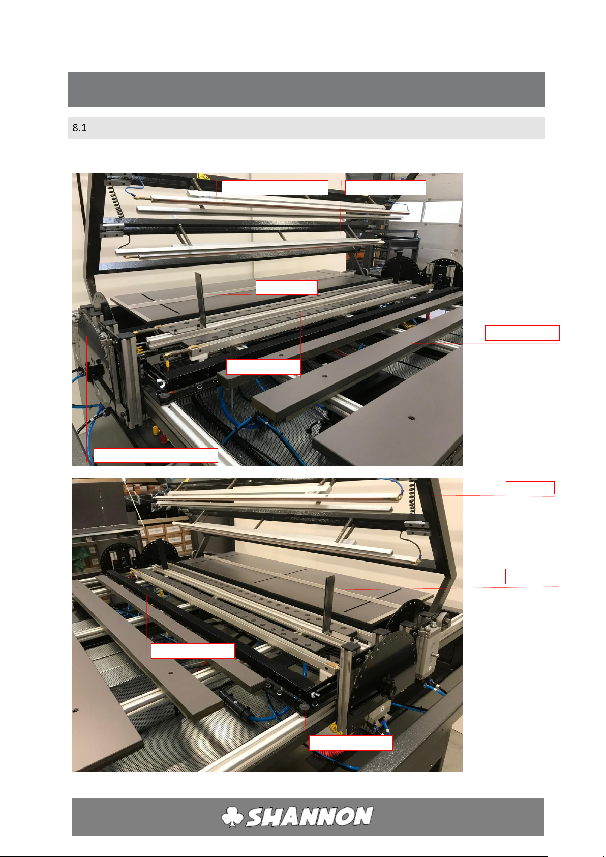
SUMMARY
The legenda of the entire machine.
Topframe
Top Heating profile (2x)
Side stop (2x)
Pressure bar (2x)
Back Stop
Gradation / protractor (4x)
Working surface
Flip over bar (2x)
Vacuüm bar (2x)
Fixing wheel (2x)

ABM-D 135
12-12-2018
-10-
Ruben Rapati
AIR/TIMER UNIT
The air/timer unit is a combined unit for the control of the
topframe and to set the cycle time. The machine closes,
and the vacuum starts when the foot switch is used. The
heating time starts when the machine is closed. The
machine opens when the time reached its value. The
plastic sheet is still held into place by the vacuum system,
and the flip(s) are turned to bend the plastic sheet. The
turning time can be set by the timer unit. The angle in
which the sheet it bent can be set manually. While the
sheet is bent, cool air is blown onto the crease to cool the
sheet. The timer will then reset back to zero
A. Connection foot switch B. On/off switch
C. Switch for 1 or 2 bend. D. Timer unit
TIMER UNIT
Button
Function
Esc
cancel
+
increase value
-
decrease value
OK
confirm
►
move right
▼
move down
▲
move up
◄
move left
There are 4 adjustable digits on the screen. From E to H.
E. The time that counts until the set turning and cooling time is over and the cycle ends.
After this time a loud alarm is heard to notify the operator that flip over bar is moving.
F. The time that the sheets need to be heated and the machine is closed.
G. The time that the sheets need to cool, before the machine resets.
H. The amount of cycles made. Needs to manually put back to zero.
D
C
A
B
G
F
E
H
ABM-D 135
12-12-2018
-11-
Ruben Rapati
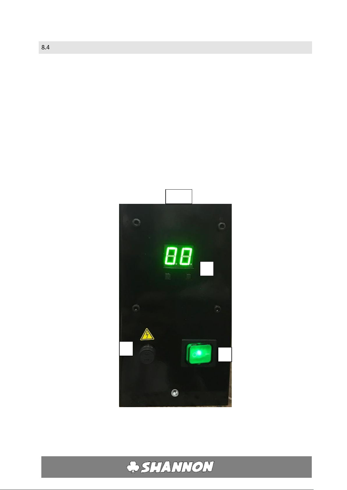
CONTROL UNIT
The control unit contains an electronic controller that can be used to set the
temperature of the filament.
The 2 temperature controllers on the left side are used for the top heating profiles.
Marked by the same colors. (black and blue)
The 2 temperature controllers on the right side of the machine are used for the
bottom heating profiles. Marked by the same colors ( red and yellow)
The bottom profiles only heat up after the footswitch has been activated.
I. On/off switch.
J. Temperature adjustment.
K. Fuse.
J
I
K
Front
ABM-D 135
12-12-2018
-12-
Ruben Rapati
9INSTALLATION
ASSEMBLY
1. Remove packaging and blocking of top frame.
2. Place the machine on a level floor with sufficient space around and above the
machine.
3. Ensure there is adequate ventilation and lighting at the workplace.
4. Avoid draughts, in order to prevent uneven heating.
CONNECTING FOOT SWITCH
Connect the plug of the foot switch on the corresponding socket (a) at the front
side of the timer unit. See 10.2
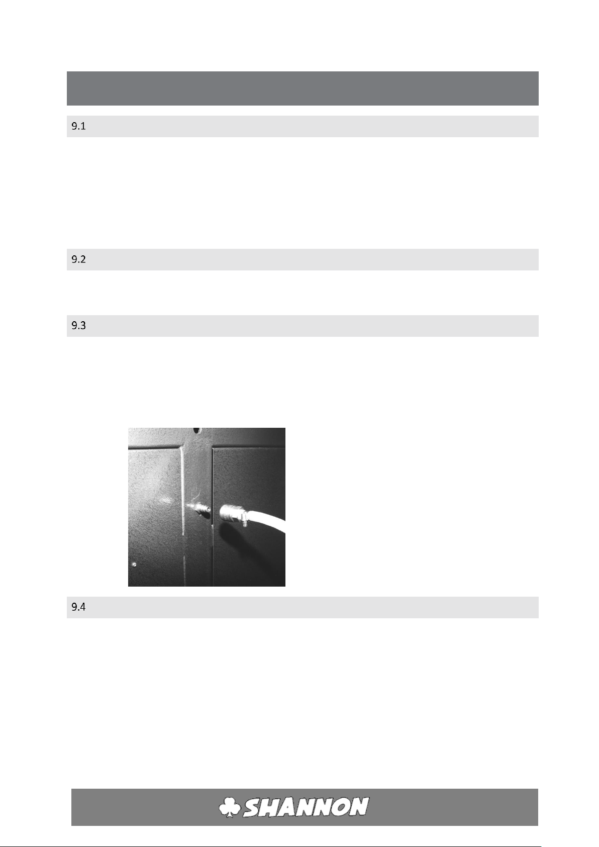
CONNECTING COMPRESSED AIR
1. Check that the heating profiles and pressure bars in the top frame are firmly
attached.
2. Using a quick-action coupling (female supplied with the machine) connect to male
connector situated on the back of machine. Connect to your compressed air
system or compressor. (minimum 6 Bar)
CONNECTING POWER
1. Check that all switches of the control units are in the 0-position.
2. Put the plug into the socket. (single phase)

ABM-D 135
12-12-2018
-13-
Ruben Rapati
10 OPERATION
PREPARATION
1. Check that the air pressure is connected.
2. Clear the working surface.
3. Check that the heating profiles are properly connected to the colored chassis
connectors.
4. Check that all the upper heating element and pressure bars are firmly attached to
the top frame.
SWICHTING ON MACHINE AND HEATING
1. Turn the main switch on the right hand side.
2. Switch on the temperature controllers that are needed (switch I, page 11)
SETTING TEMPERATURE
The temperature of the profiles can be set using the temperature control.
1. To increase the temperature, push right colored button .
(for bottom heaters this is only possible when machine is in cycle)
2. To decrease the temperature, push left colored button.
(for bottom heaters this is only possible when machine is in cycle)
3. Check if the heating element warms up.

ABM-D 135
12-12-2018
-14-
Ruben Rapati
SETTING CYCLE TIME
The heating time during which the machine is closed to heat the plastic sheet can be
set on the timer unit.
See E, F, G and H on page 10
1. Switch between values withe the ▼/▲buttons.
2. Increase of decrease the value with the +/- buttons
3. Cancel the value with the “ESC” button
4. Confirm the value with the “OK” button
FOOT SWITCH
The top frame and vacuum are activated by pressure on the pedal of the foot switch.
SETTING AIR PRESSURE
The pressure for the system is adjusted by the factory on the right value (6 bar).
This can be changed inside the machine by a valve and air pressure indicator.

ABM-D 135
12-12-2018
-15-
Ruben Rapati
11 ADJUSTMENT
SAFETY PRECAUTIONS
Always take the following safety precautions before adjusting the clamp bars:
1. Ensure that the upper heating profiles and pressure bars are firmly attached.
2. Switch off the heating elements (switch I, page 11).
3. Clear the working surface.
4. Allow the heating elements to cool for at least 10 minutes.
PRESSURE BAR AND UPPER HEATING PROFILES
1. Disengage the air connection.
2. The top frame will then slowly lower while air escapes.
3. Loosen the socket head screws on the support bar clamps of the pressure bar or
upper heating profiles one turn.
4. Hold the pressure bar or heating profile at the sides, left and right, and slide it into
the desired position. Move the support bar parallel to the front of the top frame.
5. Tighten the support bar clamps again.
6. Switch on the machine again as in Section 12.
The upper heating elements and pressure bars may fall out of the top frame if they
are loose or not properly attached.
UPPER HEATING PROFILE HEIGHT
1. Set the timer (F, page 10) to at least 160sec. With this time setting the machine
will remain closed for long enough to adjust the element height.
2. Place a test piece of the plastic to be processed on the working surface.
3. Make sure all temperature controllers are switch off (switch I, page 11)
4. Lower the top frame (foot switch).
5. Adjust the height of the profile using the adjusting nuts on the upper heating
profiles.
6. Adjust the height so that the profile just not touches the plastic .
7. Open the top frame by pressing the emergency stop.
8. Reset the emergency stop.
9. Adjust the timer (switch I, page 11) again.
10. Start the machine again as in section 12.

ABM-D 135
12-12-2018
-16-
Ruben Rapati
LOWER HEATING PROFILE POSITIONING
Only the front heating profile can be changed in position.
1Clear the working surface.
2Loosen the fixing wheels left and right (page 9)
3Turn the wheel (K) till the orange indicator shows the correct distance between
the 2 heating wires of the profiles in millimeters.
4Tighten the fixing wheels again. (page 9)
PARALLEL BACKSTOP
1. Loosen the nuts on the stop one half turn.
2. Slide the stop into the desired position.
3. Tighten the nuts.
Always ensure that the stop is placed in such a way that heating elements or
pressure bars cannot hit the stop as they are lowered.
ANGULAR STOP
1. Loosen the nut on the protractor.
2. Put the nut into the desired position.
3. Tighten the nut.
4. Make sure both left and right side are placed in the same position.
5. Run the machine without a piece of plastic, to check if the set angle is accurate
enoug
K

ABM-D 135
12-12-2018
-17-
Ruben Rapati
12 MAINTENANCE
This machine needs little maintenance. Remove loose dirt once in a while.
SAFETY PRECAUTIONS
1. Switch of the main switch (right hand side of machine).
2. Clear the working surface.
3. Allow the heating profiles to cool for at least 10 minutes.
4. Disengage the air connection.
5. Remove the plug from the socket.
TENSIONING AND CHANGING FILAMENT
1. Turn the filament to the lowest position. (Only bottom heating).
2. Hold the end of the wire on the right with pliers and undo screw in the wire
pin. (Use socket screw key no. 1½ or 2 )
3. Pull the wire taut with pliers and tension the spring.
4. Tighten the socket head screw firmly again.
5. Cut off the end of the filament. Always leave 8-10 mm projecting in order to be able to tension the
filament again. Bend the projecting piece down
Attention! The end of the filament is sharp.
10 minutes
Wire

ABM-D 135
12-12-2018
-18-
Ruben Rapati
LUBRICATION POINTS
The following points should be lubricated with a drop of oil or grease once a year:
1. Bearing cilinder: underside.
2. The lubrication point can be accessed from the rear of the machine by removing
back plates.
3. Bearing cilinder: upperside.
4. The lubrication point can be reached by removing the solid core strips on the
middle of the machine.
5. Bearings (left an right of upper frame)
PROFILES
The heating profiles work more effectively when it is clean. Remove dirt and deposits
from the aluminum profiles. Blow away loose dirt and brush them clean.
WATER SEPARATOR
Check if there is water in the water separator and remove it if necessary. The water
separator is situated on the left side of the air/timer unit. If there is water in the glass
holder, it should be drained off.
1. Switch off machine.
2. Remove Trespa working surface from the front of the machine.
3. Hold a small container under the nipple and slowly open the nipple. All the water
will then run out of the glass holder.
4. Close the drain nipple by hand.
5. Switch the machine on again.

ABM-D 135
12-12-2018
-19-
Ruben Rapati
13 FUSES
A maintenance engineer should always be alerted when a fuse blows. Do not replace
the fuse until the short circuit has been corrected.
SAFETY PRECAUTIONS
Before replacing a fuse always take the following safety precautions:
1. Switch the main switch off.
2. Remove plug from socket.
FUSES CONTROL UNIT
1. Open the fuse holder (K, page 11) by pushing it in and turn to the left. The fuse will
come out.
2. Verify and replace the fuse (if necessary) in the reversed order.
N.B. Fuse 6,3x32mm; 5 AT.
Table of contents
Other Shannon Cutter manuals

Shannon
Shannon HRP 220 User manual

Shannon
Shannon HRT 220 User manual

Shannon
Shannon HR 220-300 User manual

Shannon
Shannon AFF/D 135 User manual

Shannon
Shannon HRK 65 User manual

Shannon
Shannon HRT/D 300 User manual

Shannon
Shannon HRP/D User manual

Shannon
Shannon HRP/S User manual

Shannon
Shannon HRT 65 User manual
Popular Cutter manuals by other brands


Jenlis
Jenlis Weed Razer Pro product manual

HERKULES
HERKULES H-FS 618 Original operating instructions

EINHELL
EINHELL TPR 180 operating instructions

THERMACUT
THERMACUT EX-TRACK PA-1 operating instructions

VonHaus
VonHaus 3500079 instruction manual

Reliable Equipment
Reliable Equipment REL-58MC Operator's guide


