Shannon HRT/D 300 User manual

User’s guide
English
Plastic Bending Machine
HRT/D

User’s guide
HRT/D
-1-
HS
User’s Guide
Plastic bending
machine
HRT/D 300
1995 SHANNON BV. All rights reserved.
No part of this User's Guide may be photocopied, altered
or translated without prior written consent.
Information contained in this User's Guide is subject
to change without notice.

User’s guide
HRT/D
-2-
HS
Contents
Contents 2
Introduction 3
1 Description of the machine 4
2 Technical data 5
3 Safety instructions 6
4 Installation 7
4.1 Assembly 7
4.2 Connecting power cable 7
5 Operation 8
5.1 Preparation 8
5.2 Switching on control units 8
5.3 Setting temperature 8
5.4 Trouble shooting 8
5.5 Setting transport system 9
6 Adjustment 10
6.1 Safety measures 10
6.2 Lower heating element 10
6.3 Lower filament height 11
6.4Stop 12
7 Maintenance 13
7.1 Safety measures 13
7.2 Profiles 13
8 Tensioning and changing filament 14
8.1 Safety measures 14
8.2 Tensioning 14
8.3 Changing 15
9 Fuse 17
9.1 Safety measures 17
9.2 Control unit fuse 17
9.3 Restoring circuit breaker 18
Annexes 19
A Options 19
Accessories 20
Equipment 20
B Service and warranty 22

User’s guide
HRT/D
-3-
HS
Introduction
Congratulations on purchasing the Shannon HRT/D plastic
bending-machine.
Read this Guide completely before installing and using the
machine.
We want to keep in contact and to know how you find the
HRT/D. We are always willing to advise on the use of the
machine and its accessories.
SHANNON BV
Turfschipper 11 - 13
2292 JC WATERINGEN
P.O. box 84
2290 AB WATERINGEN
The Netherlands (EC)
Tel: +31 (0)174-225 240
Fax: +31 (0)174-225 249
E-mail: [email protected]
I-net: www.shannon.nl

User’s guide
HRT/D
-4-
HS
Description of the machine
The Shannon HRT/D plastic bending machine is a rapidly
convertible machine for the production of very large series of
items with multiple bends for the plastic sheet processing
industry.
The machine has three adjustable heating elements as
standard. The temperature of which can be adjusted
independently by electronic controls.
The filaments of the heating elements on the working
surface are adjustable in height.
The work piece can be heated from one side and it is
possible to bend sheet up to 8 mm thick.
This machine is equipped with an easily adjustable and
controllable transport- and feed system. Multiple feed belts
transport the work piece over the heating elements from
the right to the left of the working surface. This way all the
sheets are equally heated and the full table length is in use.
The working surface is made of scratch-resistant solid core
material with which the space between the zones to be
heated can be filled to support the plastic sheet.
When heated, thermoplastics become so flexible that they can
be shaped. When a plastic sheet is heated to its softening point
in a narrow zone, if can be bent to any angle desired.
The bending radius is determined by the width of the heated
zone. The zone is determined by the thickness of the material,
the type of heating element and the distance between the
plastic and the filament.
Every plastic has its specific softening point. By co-ordinating
the temperature, heated zone and heating time all kinds of
thermoplastic can be processed.
1

User’s guide
HRT/D
-5-
HS
Technical Data
model
HRT/D
Assembly
control
2 (max. 4)
lower heating element
2 (max: 4 & min: 1), fitted with single filament
Electrical
voltage
power
fuse
control unit
220/240 V~
1000 VA
5 AT
max. power requirement
4.000 VA
network circuit breaker
max. 16 A
network connection
CEE 7/4 16A 2P+PE
filament
0-30 V, 0-19 A ~
Driving motor Voltage
220 V
Power
0,37 Kw
Réglage de vitesse Voltage
220 V
Power
0,37 Kw
Horsepower
1.500 (R/pm)
Mechanical
gradation of stop
max 1000 mm
dimensions
3390x1300x1092 mm (lxwxh)
weight
550 Kg
life of filament
Approx. 600 hours
Functional
bending width
3000 mm
mutually extendible
20 - 1000 mm
sheet thickness
1 - 8 mm (depending on heating element)
temperature range filament
20-600 C
filament height adjustment
bottom
1 - 6 mm
Ambient
temperature
18-30 C
humidity of the air
50-80 % (no condensed)
Miscellaneous
set of socket screw keys
2, 3, 5, 6mm 1 x
spare fuse
6.3x32 5 AT 4 x
spare filament
1.6 x 3150 mm 4 x
2
User’s guide
HRT/D
-6-
HS
Safety instructions
SAFETY INSTRUCTIONS:
To ensure safety when using the machine you should read this
User's Guide carefully and follow the safety instructions closely.
Attention!
The machine contains parts which are hot. Touching them will
cause burns.
Allow hot parts to cool sufficiently (at least 10 minutes) before
touching them.
Never touch the filaments or the reflectors when the machine
is in operation.
Always wear close-fitting clothing.
Be particularly careful of sleeves and always tie back long hair.
Never leave objects on the working surface.
The machine may only be used for heating narrow zones in flat
plastic sheet.
Any other use could lead to very hazardous situations or cause
damage to the machine!
Before commissioning and servicing always check the
connection cable and plug for defects.
When servicing switch off the machine and remove the plug
from the socket.
Never introduce objects or material into the machine from the
rear.
Never leave the machine unattended without switching it off.
3

User’s guide
HRT/D
-7-
HS
Installation
4.1 ASSEMBLY
1. Remove packaging
2. Place the machine on a level floor with sufficient space around and above the machine.
3. Level the working surface of the machine, using shims under the feet if necessary.
4. Ensure there is adequate ventilation and lighting at the workplace.
5. Avoid draughts, in order to prevent uneven heating.
When moving the machine with a forklift truck ensure that the machine is supported
right in the centre.
Also use sufficiently long prongs on the forklift truck.
4.2 CONNECTING POWER CABLE
1. Check that the rating of the electrical system is adequate (see technical data).
2. Plug in the machine.
4

User’s guide
HRT/D
-8-
HS
Operation
5.1 PREPARATION
1. Clear the working surface.
2. Check that all the heating elements are connected to the control units.
3. Check that no scraps of material remain in the reflectors.
4. Switch off all the control units (position "").
5. Turn on the main switch (position I).
5.2 SWITCHING ON HEATING
ELEMENTS
Each heating element can be switched on and controlled
individually.
1. Switch on control unit with switch H.
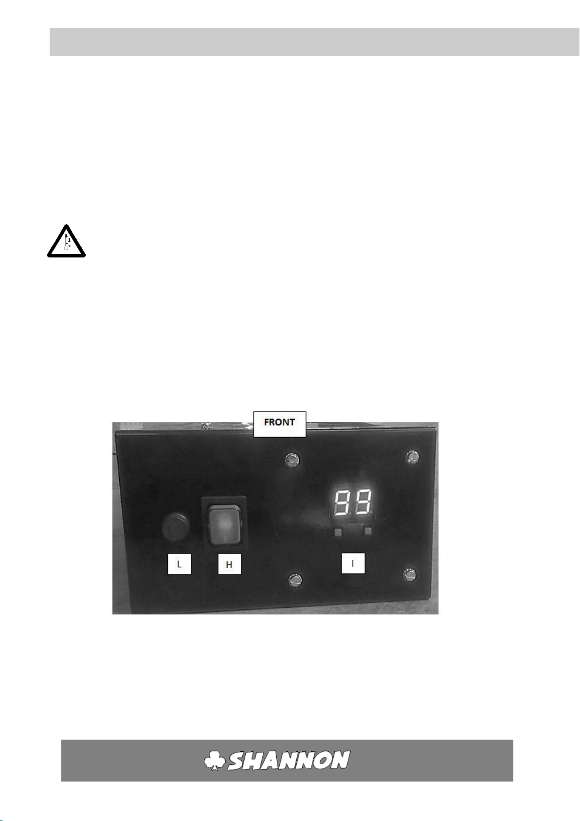
5.3 SETTING THE TEMPERATURE
The temperature of the filament can be set using the temperature control.
1. When turning on the on/off switch, the display will show the value that was last saved (keeping the
machine on a certain value for >20 seconds will make it remember this value).
2. Press the right button (arrow up) to increase the value, up to 99 (keeping this pressed in will make
the value cycle much faster)
3. Press the left button (arrow down) to decrease the value, down to 00 (keeping this pressed in will
make the value cycle much faster)
4. Press both buttons at the same time to go directly to 00. Doing this also resets the machine.
5.4 TROUBLE SHOOTING
5
Error message
Meaning
Solution
E1
The wire is loose (not connected)
Turn off the machine, check the filament, and reset the
machine
(see §9.1 for changing filament)
Note: Between the values 00 and 04, this fault cannot be
detected
E2
The wire is loose (spark detection)
Check the connection of the filament
Check the filament, and reset the machine
This fault can also be reset by the arrow down button
(see §9.1 for changing filament)
E9
Broken circuit board
Contact the supplier for a new circuit board
Empty display
No power
Alert a maintenance engineer
Check the fuse (see §10.1)
Check the power supply cable
Contact the supplier if necessary
80

User’s guide
HRT/D
-9-
HS
Operation 5
5.5 SWITCHING ON TRANSPORTSYSTEM
Screen buttons[6]
Button
function
Esc
Cancel
+
Increase value
-
Decrease value
OK
Confirm
►
Move right
▼
Move down
▲
Move up
◄
Move left
Transport system:
Before using the transport system, first turn the speed regulator[5] all
the way to the left. To activate the transport system, switch the green
button[4] so that it lights up. Then, turn the speed regulator[5] to
regulate the speed. On the right you’ll find a table which gives an
indication on how fast the track goes from 1 end of the machine to the
other, on each rotation of the knob.
Feeding system:
1. Press the left green button[2] so that it lights up. The
control system of the feeding system is now activated.
2. There are three numbers now on the display ranked
from top to bottom as:
a. [7] The number of cycles that the machine will
operate (the number of plastic sheets that are
loaded)
b. [8] The time in seconds that the pusher is
reloading a new piece of plastic.
c. [9] The time in seconds that the feeding system
is pushing a new piece of plastic.
3. For first time usage, set all the values on 10:
a. Swap between values by using the ▼/▲buttons.
b. Increase or decrease the value by using +/-.
c. Cancel the value by using he “ESC” button.
d. Confirm the value by using the “OK” button.
4. Press the round red button[1] to stop the machine
5. Press the green round button[3] to active the pneumatics. The feeding system will
begin working now.
6. The feeding system can be fine-tuned in the following ways:
a. If the system stops too fast, increase the cycle number by increasing the top
value in the display.
b. If the reloading time is too long, decrease the second value on the display.
c. If the pushing time is too long, decrease the third value on the display.
Full knob rotation
Time (in seconds)
1
70
2
35
3
24
4
19
5
16
6
14
7
12.5
8
12
9
11.5
10
11
1
2
3
4
5
6
7
8
9
User’s guide
HRT/D
-10-
HS
Adjustment
6.1 SAFETY MEASURES
Always take the following safety measures before adjusting the heating elements:
1. Switch off the heating elements one at a time (Switch H, page 10).
2. Clear the working surface.
3. Allow the heating elements to cool for at least 10 minutes.
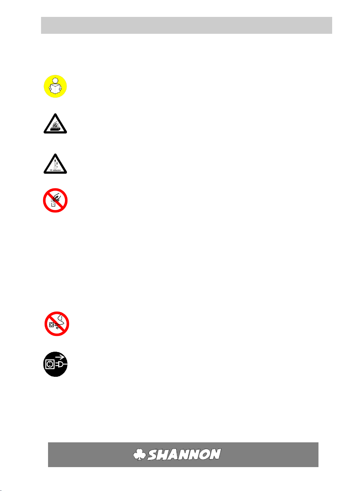
6.2 LOWER HEATING ELEMENT
1. Remove the strips of solid core material next to the heating
element to be adjusted by loosening the two socket head
screws. (Use socket screw key no. 5).
2. Loosen the socket head screws in the supporting prongs on the
left and right of the heating element one half turn.
6
2
Supporting prong
1
10 minutes
User’s guide
HRT/D
-11-
HS
Adjustment 6
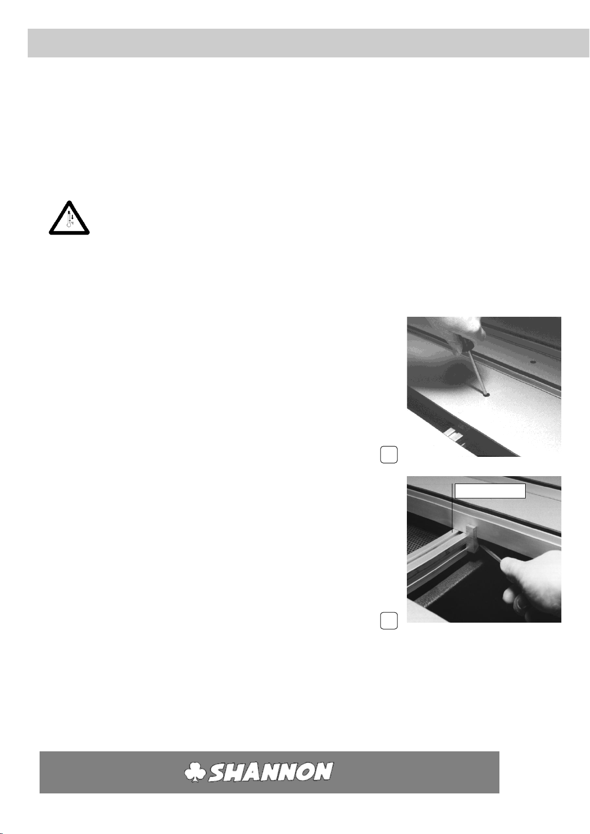
3. Loosen the socket head screw in the centre of the heating
element one half turn.
(Use socket screw key no. 3)
4. Take the heating element with both hands close to the supporting
prongs on the left and right and slide it into the desired position.
Hold the heating element parallel to the front of the machine and
the supporting prongs. This prevents the notched nuts in the
aluminium X-profiles from binding.
5. Hand tighten the socket head screws, starting in the supporting
prongs and then in the centre.
6. Position the other profiles in the same way if necessary.
7. Fill up the space between the heating elements as far as possible with solid core
strips and hand tighten them. First slide the notched nuts into the aluminium X-
profile roughly level with the holes and then lay the solid core strip on top.
8. Switch on the machine again as in Section 5.
3
4
User’s guide
HRT/D
-12-
HS
Adjustment 6
6.3 LOWER FILAMENT HEIGHT
1. Adjust the height of the filament using the knurled nut.
These can be reached from the sides. Make sure that the
filament height is the same on both sides.
2. Start up the machine again as in Section 5.
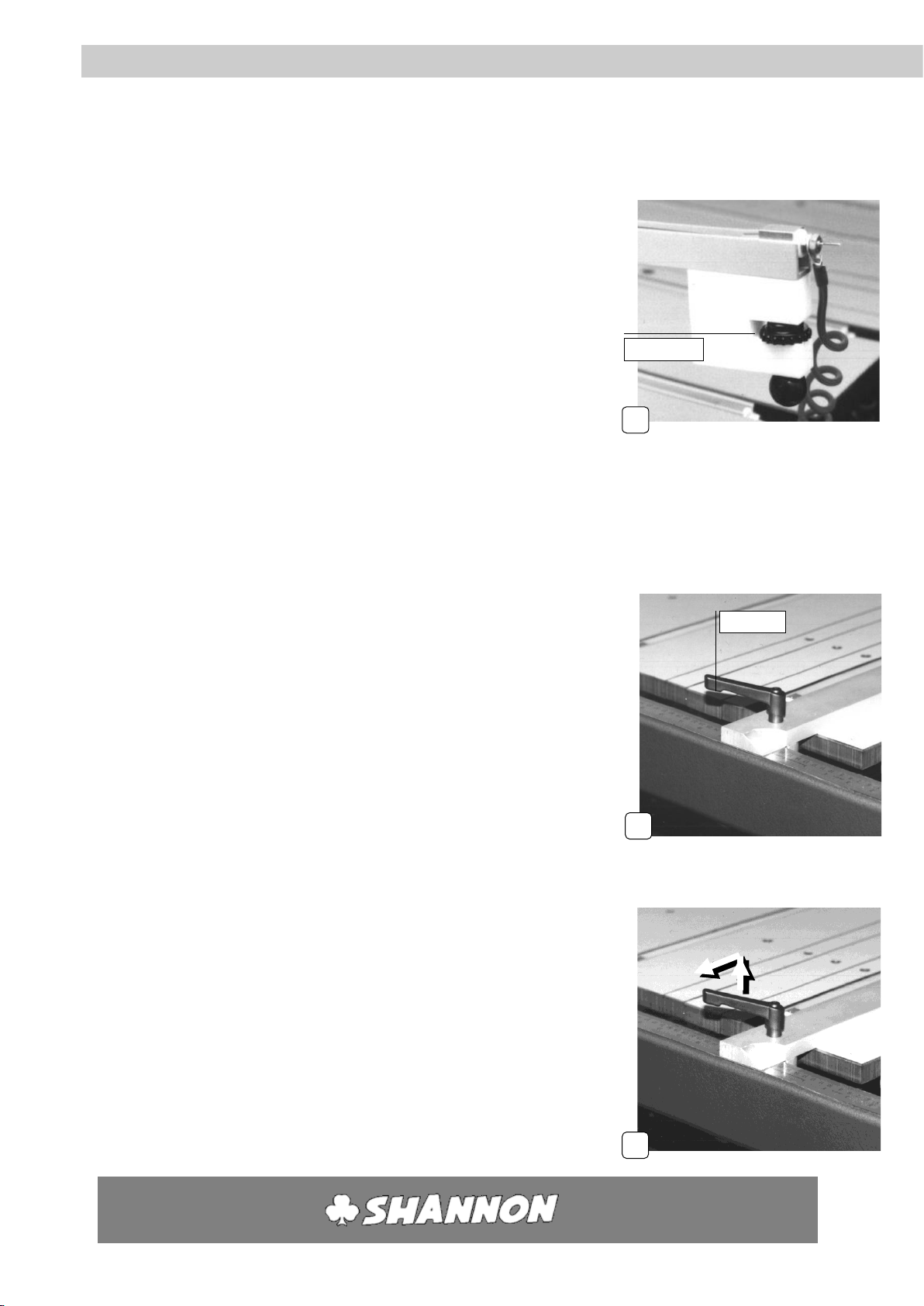
6.4 STOP
1. Loosen both the handles on the stop one half turn.
2. Slide the stop into the desired position.
Hold the guide parallel to the front of the machine. This stops
the clamping blocks from binding.
3. Tighten the handles.
4. Pull the handle upwards against the spring pressure and turn it
outwards.
1
4
1
Handles
Knurled nut

User’s guide
HRT/D
-13-
HS
Maintenance
This machine needs little maintenance. Remove loose dirt out of the machine once in a
while.
7.1 SAFETY PRECAUTIONS
1. Switch of all regulating units (switch H).
2. Clear the working surface.
3. Remove the plug from the socket.
7.2 PROFILES
The heating elements work more effectively when they are clean. Remove dirt and
deposits from the heating elements regularly. Blow away loose dirt and brush them clean.
7
User’s guide
HRT/D
-14-
HS
10 minutes
Tensioning and changing filament
8.1 SAFETY MEASURES
Before tensioning and changing the filament always take the following safety measures:
1. Clear the working surface.
2. Switch off the control units one at a time (switch H).
3. Turn off the main switch
4. Allow the heating elements to cool for at least 10 minutes.
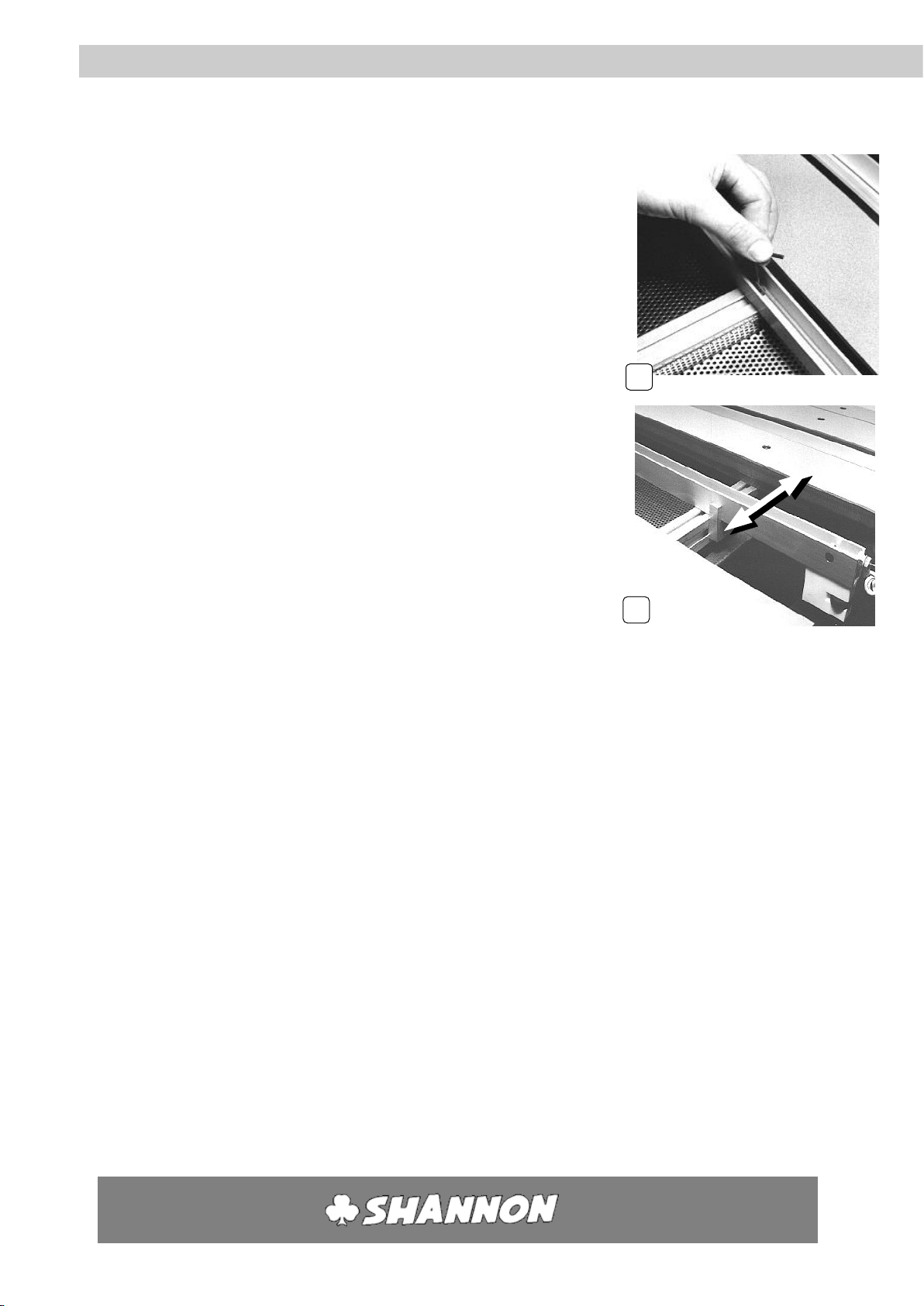
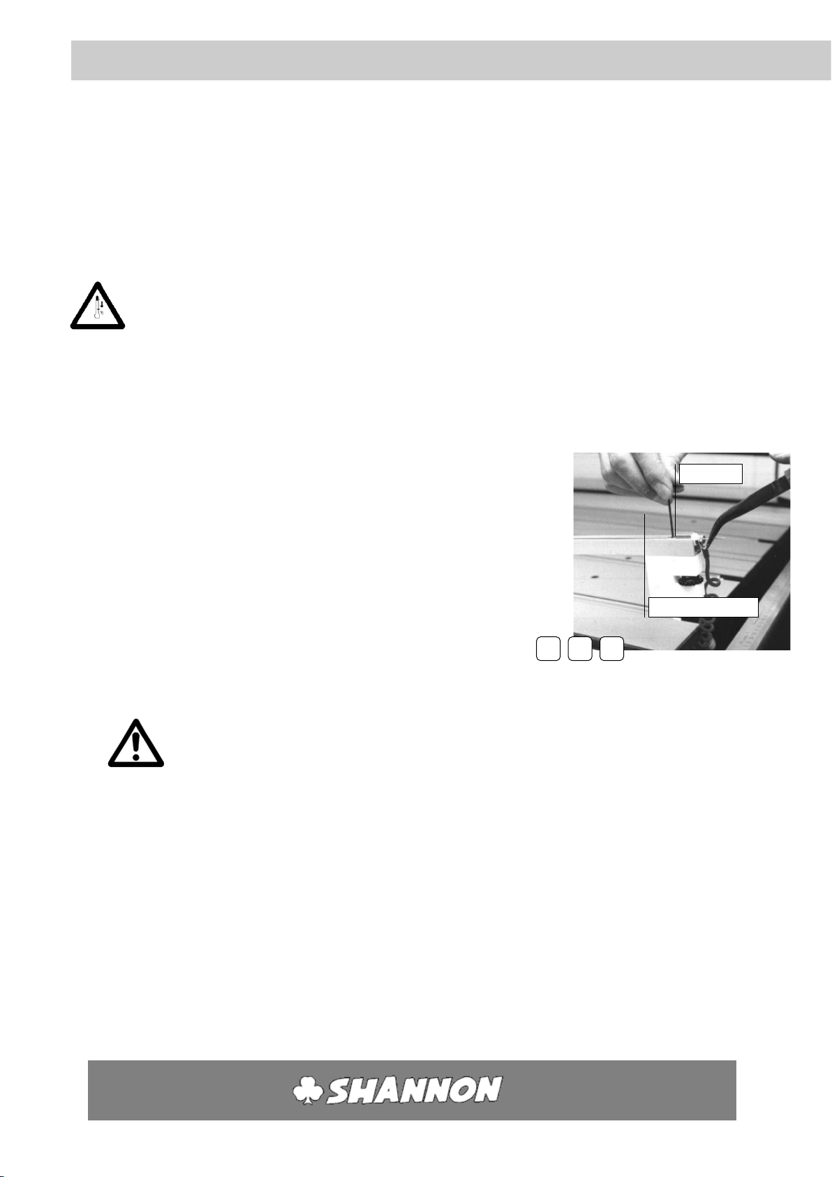
8.2 TENSIONING
1. Turn the filament to the lowest position.
2. Hold the end of the wire on the right with pliers and undo screw
in the wire pin.
(Use socket screw key no. 2)
3. Pull the wire taut with pliers and tension the spring.
4. Tighten the socket head screw firmly again.
5. Cut off the end of the filament. Always leave 8-10 mm projecting in order to be able
to tension the filament again.
Bend the projecting piece down.
Attention! The end of the filament is sharp.
8
Wire pin
Socket head screw
2
3
4

User’s guide
HRT/D
-15-
HS
Tensioning and changing the filament 8
8.3 CHANGING
1. Turn the filament to the lowest position.
2. Unscrew socket head screw in the wire pin on the right. (Use
socket screw key no.2).
3. On the left side slide the expanding pin with the spring out of
the pin block.
4. Slide the spring off the expanding pin.
5. Unscrew the expanding pin from the connection screw (incl.
connection wire).
6. Remove filament from the expanding pin and the wire pin.
7. Slide a new wire into the expanding pin and make sure that the
eye is pulled well into the pin.
8. Screw the expanding pin on the connection screw (incl. connection wire) and attach
firmly.
Take care not to damage the expanding pin. Tightening firmly by hand is sufficient.
5
Connection screw
Expanding pin
7
Eye
2
User’s guide
HRT/D
-16-
HS
Tensioning and changing filament 8
9. Slide the spring over the filament and slide the filament through to the expanding
pin.
10. Slide the filament with expanding pin through the white insulation sleeve of the pin
block and pull it through as far as possible.
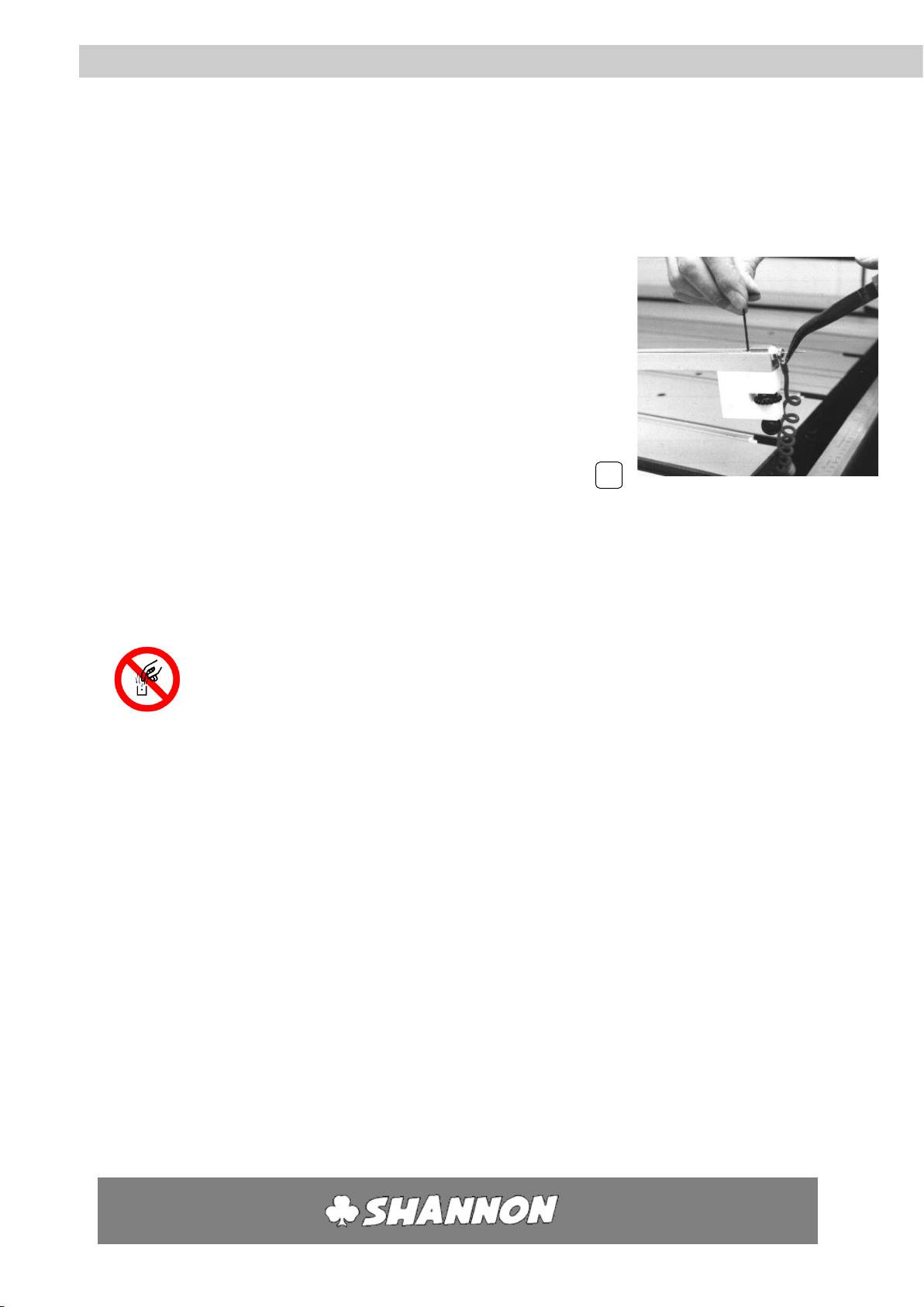
11. Then insert the end of the filament in the wire pin. Pull it taut
and tension the spring with pliers.
12. Tighten the socket head screw.
(Use socket screw key no. 2).
13. Switch on the machine and the control unit corresponding to the replaced filament
(main switch, control unit switch H). Then turn the temperature control (I) to the
highest position (99).
The filament will then glow red.
Never touch the filaments and the reflectors when the machine is in operation.
14. Take hold of the end of the filament with pliers and loosen the socket head
screw one half turn. (Use socket screw key no. 2).
15. Pull the filament taut and tighten the socket head screw. Check that the filament is
straight. If not, repeat this operation.
11
100
User’s guide
HRT/D
-17-
HS
Fuse
A maintenance engineer should always be alerted when a fuse blows. Do not replace the
fuse until the short circuit has been corrected.
9.1 SAFETY MEASURES
Before replacing a fuse always take the following safety measures:
1. Clear the working surface.
2. Switch the control units off one by one (switch H).
3. Switch off the main switch.
4. Remove plug from socket.
5. Allow the heating elements to cool for at least 10 minutes.
9.2 CONTROL UNIT FUSE
1. Open the fuse holder (L) by pushing it in and turn to the left. The fuse will come out.
2. Verify and replace the fuse of necessary, in the reversed order.
N.B. Fuse 6,3x32mm; 5 AT, 1 piece a control unit.
9
10 minutes

User’s guide
HRT/D
-18-
HS
Fuse 9
9.3 RESTORING CIRCUIT BREAKER
1. Remove a number of solid core strips in the centre of the machine.
The circuit breaker which is at the front of the main switch box is now visible. When the
switch is down ("off"), the circuit breaker is switched off.
2. Switch on the circuit breaker by pushing the switch up.
2

User’s guide
HRT/D
-19-
HS
Annex
OPTIONS
Additional heating elements can easily be fitted to the machine.
All extensions and accessories are easy for the customer to mount and connect.
Non-standard sizes and quantities on request.
Regulating units
Maximum number of controls per machine is 4
Each regulating unit controls one filament.
Heating elements
Heating elements are available in a variety of widths and with 1 or 2 filaments.
Heating elements with 2 filaments are suitable for heating wide zones and for obtaining a
large radius.
Maximum number of heating elements: 4
Number of filaments per heating
element
Profile
width*(internal)
1 filament
20
40
2 filaments
50
3 filaments
78
*measuring in mm
All heating elements are provided with fastening material and connecting cables.
Service Contract
Shannon offers you an opportunity to take out a service contract. Let us tell you about it.
Spares
Part
Size/value
Filament
1,6 x 3.150 mm.
Fuse
5 AT
Wire tensioning set
1,6 mm
A
Table of contents
Other Shannon Cutter manuals

Shannon
Shannon HRT 65 User manual

Shannon
Shannon AFF/D 135 User manual

Shannon
Shannon HRT 220 User manual

Shannon
Shannon ABM-D 135 User manual

Shannon
Shannon HRP 220 User manual

Shannon
Shannon HR 220-300 User manual

Shannon
Shannon HRP/S User manual

Shannon
Shannon HRK 65 User manual

Shannon
Shannon HRP/D User manual


