Sharp FU-60SE-TA User manual

1
FU-60SE-TA
S4310FU60SETA
AIR PURIFIER
In the interests of user-safety (Required by safety regulations
in some countries) the set should be restored to its original
condition and only parts identical to those specified should be
used.
SERVICE MANUAL
FU-60SE-TA
MODEL
SHARP CORPORATION
Page
SAFETY PRECAUTIONS ..................................................................................................................................2
FOR EFFECTIVELY USING THIS PRODUCT..................................................................................................4
SPECIFICATIONS .............................................................................................................................................5
NAMES OF PARTS .......................................................................................................................................... 6
PREPARATION ................................................................................................................................................ 8
CARE AND MAINTENANCE ............................................................................................................................ 9
ABOUT THE FUNCTION................................................................................................................................ 11
ELECTRIC CIRCUIT........................................................................................................................................12
WIRING DIAGRAM..........................................................................................................................................12
SPECIFIC MODEL LIST ..................................................................................................................................17
TROUBLESHOOTING GUIDE ........................................................................................................................22
REPLACEMENT OF MAIN PARTS .................................................................................................................24
USE RESIN TABLE .........................................................................................................................................31
REPLACEMENT PARTS LIST ........................................................................................................................32
TABLE OF CONTENTS
Tabletop

2
FU-60SE-TA
SPREAFETY PRECAUTIONS
• Do not use the unit if the Power Cord or Plug is damaged or the connection to the wall outlet
is loose.
Electrical shock, short circuit and/or fire may occur as a result.
•Do not damage, break, coat, forcefully bend, pull, twist, bundle, pinch or place heavy objects
on the power cord.
If the power cord is damaged, fire and/or electrical shock may occur as a result.
• Use AC 220-240V only.
Fire and/or electrical shock may occur as a result.
•Do not modify. Repair and disassembly of this product are to be performed by authorized
service personnel only.
Fire, electrical shock and/or bodily injury may occur if not.
For repair, contact your dealer of purchase or the nearest Sharp Service Centre.
•Periodically remove dust from the Power Plug
Accumulated dust on the Power Plug may cause bad insulation from humidity, etc.
Fire and/or electrical shock may occur as a result.
• When cleaning the unit, be sure to remove the Power Plug from the wall outlet.
In addition, never handle the Power Plug with wet hands.
Electrical shock and/or bodily injury may occur as a result.
• Do not use the unit where there are oil ingredients such as cooking oil, etc., in the air.
Cracking of the unit surface may occur as a result.
•Do not wipe the unit with benzene or paint thinner.Also, do not spray insecticides on the unit.
Cracking, electrical shock and/or fire may occur as a result.
• Do not operate the unit when using indoor smoke-generating insecticides.
Chemical ingredients may accumulate within the unit and then discharge from theAir Outlet when the
unit operates. Discharge of such chemicals may be unhealthy to your body.
• Do not allow the unit to intake flammable gases, sparks from lit cigarettes, incense, etc.
The unit may ignite as a result.
• Do not use the unit where it is humid, such as in a bathroom, or where the unit may get wet.
Electrical shock and/or malfunction may occur as a result.
• Do not insert fingers or foreign objects into the intake or Air Outlet.
Electrical shock and/or malfunction may occur as a result.
• When removing the Power Plug, always hold the Plug and never pull the cord.
Electrical shock and/or fire from short circuit may occur as a result.
•Ventilate when using the unit along with a heating appliance.
The unit can not remove carbon monoxide, so carbon monoxide poisoning may occur as a result by
a heating appliance.
• Remove the Power Plug when not using the unit for a long time.
Electrical shock from bad insulation and/or fire from short circuit may occur as a result.
•If the supply cord is damaged, it must be replaced by the manufacturer or its service agent or
similarly qualified person in order to avoid a hazard.
•The batteries must be removed from the appliance before it is scrapped and that they are
disposed of safely.

3
FU-60SE-TA
CAUTIONS CONCERNING THE OPERATION OF THIS PRODUCT
• Do not block the intake and Air Outlet.
•Do not use the unit near or on hot objects, such as a stove, etc.Also, do not use the unit where
it may come into contact with steam.
• Do not use the unit on its side.
Deformation, malfunction and/or overheating of the motor may occur as a result.
• Do not install when there is generation of lampblack, such as in a kitchen.
• Do not use detergent when cleaning the unit.
The unit surface may become damaged or cracked.
In addition, the sensors may malfunction as a result.
• Do not operate the unit without the filter.
It will have no purification effect. In addition, it becomes the cause of the trouble.
•Do not wash and reuse filters.
They do not have effect, and it becomes an electric shock and the cause of the trouble.
•When transporting the unit, always hold the handle on the back of the unit.
Holding the Front Panel when carrying may cause it to detach, thus dropping the unit and resulting in
bodily injury.
REMOTE CONTROL LIMITATIONS
DO NOT USE THE REMOTE CONTROL IN THE FOLLOWING LOCATIONS
•Any location where there are inverter lighting equipment or electronic spontaneous lighting
equipment
The Remote Control may become inoperative. In this case, move away from such lighting equipment
or change direction.
• Location exposed to direct sunlight
The unit may not receive signals from the Remote Control.
The unit may not respond to the signals of the Remote Control if the ends of fluorescent lighting
become black or lights flicker due to the depletion of service life; however, this is not a malfunction of
the Remote Control or the Main unit. In this case, replace the lighting with new fluorescent tubes.
INSTALLATION GUIDELINES
•Leave at least 2m of space from equipments which involve electric wave such as televisions,
radios or wave clocks.
Electrical interference may occur if not.
• Leave at least 60cm of space from the wall
The motor may overheat, causing malfunction if not.
•Avoid a location where sensors are exposed to direct wind
The unit may not operate properly.
•Avoid a location where curtains, etc., come into contact with the intake or Air Outlet.
Curtains, etc., may become dirty or malfunction may occur as a result.
EFFECTIVE OPERATION
•Place on a stable surface with sufficient air circulation
FILTER GUIDELINES
•Do not wash and reuse HEPAFilter andActive Carbon Filter. They do not effect, and may become a
cause of electric shock and trouble.
• The wall behind the Air Outlet may become dirty as time passes. When using the unit for extensive
period in the same location, use a vinyl sheet, etc., to prevent the wall from becoming dirty. In addi-
tion, periodically clean the wall, etc.

4
FU-60SE-TA
FOR EFFECTIVELY USING THIS PRODUCT
HOW THE AIR PURIFIER WORKS
The air purifier uses the internal fan to intake the air in the room through the intake port and discharges the air through
the exhaust port after cleaning the air is passed through the deodorizing filter (Active carbon filter) and dust collection
filter (HEPA filter). The unit then repeats this process. Odor ingredients are removed by repeatedly passing them
through the Deodorizing filter for gradual adsorption.(At this time, the dust collection filter also adsorbs odor ingredients.)
FOR UNDERSTANDING THE PRODUCT
Some of the odor ingredients absorbed by the filters become separated and are discharged through the air outlet as
odor. Depending on the usage environment, this odor may become strong in several months and the air outletmay
smell. In this case, replace the filters.
GUIDE FOR OPERATION
(1) ODOR SENSOR
In addition to odor such as cigarette smoke and pet odor, the odor sensor also responds to the following.
Insecticide, cosmetics, spray, alcohol.
Sudden changes in temperature or humidity.
When the unit is in automatic operation and cosmetics or the like are used in a closed room, it is normal for the
sensor to respond by increasing the air flow. If this is not desirable, change the sensitivity of the sensor.
(2) DUST SENSOR
The dust sensor detects dust particles in room air, such as cigarette smoke and house dust.
Compared with cigarette smoke, the amount of dust released when making your bed is so small that it may not
be detected by the dust sensor. Therefore, the amount of dust seen with the eye may differ from the indication
of the clean-sign lamp.
(3) FILTER RESET BUTTON
After replacing filters, make sure to connect the power plug to a wall outlet, and press the filter
Reset button on the main unit or on the remote control. The "BEEP" sound indicates that the stored
operating time has been reset. If the filter lamp is lit at that time, it will now go off.
(4) SENSOR SENSITIVITY SWITCH
The sensitivity of odor and dust sensors is adjustable.
" Standard " is set by default. This setting is for normal use.
Set to " High " if you feel the sensitivity is low.

5
FU-60SE-TA
SPECIFICATIONS
Type FU-60SE-TA
Power supply 220V 50Hz
Fan level adjustment Max High Medium Silent
Rated power (W) 53 19 6 4
Fan level (m3 /hour) 360 218 95 43
Fan rotation speed (r.p.m.) 970±10
660±20
370±20 220±20
Noise (db) 50 38 23 14
Applicable floor area 1 around ~ 46m 2
Dust correcting method Mechanical purification
Protective devices Current fuse Turning off when abnormal current (2.5A) flows
Control panel MODE /
Indication lamp Operation mode Auto, Silent, Mediun, High, Max., Pollen
Air pollution level It displays Clean sign
When clean [Green]
+
_
Dirt condition (Min.) [Orange]
+
_
Dirt condition (Max) [Red]
OFF TIMER operation
A green lamp lights up at the time of off-timer operation. (1 hour, 4 hours, 8 hours)
Filter exchange lamp
Total operation time lights up in 21900 hours(one-day 12hour x 365 days x 5 years)
Remote control Operation mode
Auto, Manual (Silent, Meidum, High, Max.) Pollen, OFF Timer, Display
ON/OFF, Filter reset, Cluster ion (Auto, OFF, Clean, Ion control)
OFF TIMER time 1 hour, 4 hours, 8 hours
Outside dimension (mm) 415 (W) x 238 (D) x 572 (H)
Weight (kg) 9.3
Cord length (m) 2.5
Installation Tabletop
Accessories Operation manual, Remote controller
Batteries (size R6(AA) manganese batteries)
Replace the filter 2 HEPA filter : approx. 5 years, Deodorizating filter : approx. 5 years
Option Replace filter : FZ-60SEF (A HEPA filter and a Deodorizating filter are included)
1: Based on the standard of The Japan Electrical Manufacturers' Association, JEM1467
The size of the room to be referred to is the one in which dust concentration of 1.25mg/m 3may be reduced to
0.15mg/m 3within 30 minutes under the condition that the natural ventilation is performed once per hour.
2 : Based on the standard of The Japan Electrical Manufacturers' Association, JEM1467 Ten cigarettes are smoked
per day in the place where the air cleaner is installed.
Reduction of stand-by power consumption
While this product is plugged in, it consumes the stand-by power of approximately 0.9W to activate the electric circuit

6
FU-60SE-TA
NAMES OF PARTS
MAIN UNIT DISPLAY
AUTO Operation Lamp Fan Level Lamps
OFF Timer Display Lamps
(set using remote control)
Filter Lamp
If the Filter lamp is lit, it indicates filter
replacement period.
PLASMACLUSTER LAMP
Plasmacluster ion operation is selected using the remote
control.
Blue light
When the Plasmacluster ion operation is in Clean Mode or
AUTO Plasmacluster Ion Mode and the air in the room is
impure, the light will activate and the unit will operate in
Clean Mode.
Green light
WhenthePlasmacluster ion operationisin Ion Control Mode
orAUTO Plasmacluster Ion Mode and the air in the room is
clean, this light will activate and the unit will operate in Ion
Control Mode.
Light off
There are no ions being generated.
• The light can be turned off by using the ‘DIS-
PLAY ON/OFF Button’ on the Remote Control
even while ions are generated
(Please turn off the lights when not required.)
Pollen Mode Lamp
Remote Control Receiver
MODE/ Button
See Page E-10
(Used to select operations or turn the unit off)
Sensor Sensitivity Select Switch
The unit’s sensitivity of odor and dust detection can be adjusted.
Thissetting is factory set to “NORMAL”.And it is recommended that
you use the unit in this setting. Set the sensitivity to “SENSITIVE” if
the sensitivity seems too low depending on the room condition.
Filter Reset Button
Odor Sensor
Detects odors such as tobacco smoke, incense, pets, cos-
metics, etc.
Sensor Cover / Dust Sensor
Detects dusts, smoke, pollen, house dust, etc. See Page E-
12,E-13
Main unit
Filter Frame
HEPA Filter (white)
See Page E-14
(Dust collection filter)
Active Carbon Filter (black)
See Page E-14
(Deodorizing filter)
Filter Separator
Pre-Filter
Front Panel
Hook
Remote Control See Page E-11
CLEAN-SIGN
The color changes according to the air condition.
Clean (green) Slightly impure (orange) Very impure (red)
ABOUT THE CLEAN-SIGN
•Thesensors display a CLEAN-SIGN depending on relativechanges
to the environment from the time the power plug is inserted into the
wall outlet and thereafter.
•When the air is extremely impure at the time the power plug is in-
serted, the CLEAN-SIGN may light green since the impure condi-
tion is the environment against which the sensors base the impurity
rate on. In this case, operate the unit for a while in Clean Mode first,
then switch to the desired operation mode. See Page E-11
•The CLEAN-SIGN can be turned off using the DISPLAY ON/OFF
Button of the Remote Control. See Page E-11
*Before pressing the Filter Reset But-
ton, be sure that the unit is plugged in.
There is also a Filter Reset Button on
the remote control.
Point the Remote Control toward the
main unit before pressing the Filter
Reset Button on it.

7
FU-60SE-TA
Plasmacluster
MAIN UNIT OPERATION
Main unit Controls
• AUTO
•Silent
• Medium
•High
•Max
• Pollen Mode
The unit will start operation when the MODE/ Button is pressed.
The unit will start operation in AUTO Mode (fan level).
•While operating, the Plasmacluster Lamp will be lit.
To switch operating controls, press the MODE/ Button until the desired
control is activated. (Your desired control will have its Indicator Lamp lit.)
For the best results of the room environment, set your operation control as desired.
Stop
AUTO operation
The fan level is automatically
switched (High, Medium, Si-
lent)dependingon the amount
ofimpurities in theair.Thesen-
sors detect the impurities for
efficient air purification.
Silent operation
The unit will operate quietly
using minimal air intake.
Pollen Mode Operation
The unit will operate at High level for
10 minutes, then will alternate be-
tween Medium and High.
Medium to Max operation
The unit will operate at a fan level of
medium, high or max.
For the first 30 seconds after the Power Plug is in-
sertedintothewall outlet, the unit will check the con-
dition of the air. If operation is set to ON during this
time, the CLEAN-SIGN will alternately flash green,
orange and red.
Plasmacluster Lamp
MODE/ Button
10 minutes: High fan level
20 minutes: Medium fan level
20 minutes: High fan level
Plasmacluster
AUTO
RESET
OFF
REMOTE CONTROL OPERATION
Operations available
with the Remote Control
•AUTO
•
MANUAL
• Pollen Mode
• OFF timer
•DISPLAY ON/OFF
Plasmacluster Ion Mode
selections
•
AUTO Plasmacluster Ion Mode
•Clean Mode
•Ion Control Mode
•
OFF
• When you press the POWER ON/OFF Button a short beep will
sound and operation will start. As the initial operation mode, it
automatically goes to the AUTO (Fan level) and AUTO
Plasmacluster Ion Mode.
•To stop operation, press the POWER ON/OFF Button again.
A long beep will sound and operation will stop.
POWER ON/OFF Button
Used to startAUTO operation
of the unit. A short beep will
signal that the unit is on and a
long beep means that the
units is off.
AUTO (Fan Level) Button
The fan level switches auto-
matically depending on the
amount of impurities in the air.
MANUAL (Fan Level) Button
Thefan level can be switched
betweenSilent, Medium, High
and Max.
DISPLAY ON/OFF Button
Switches the Plasmacluster
Lampand CLEAN-SIGN lamp
either ON or OFF.
•The Plasmacluster Lamp is
turned on for about 3 sec-
onds by pressing the
Plasmacluster Ion Select
Button (except the OFF but-
ton) during “DISPLAY OFF”
mode.
Transmitter
Filter Reset Button
Press this button after replacing
the filters.
Pollen Mode Operation Button
The unit operates effectively
when you suspect there is pol-
len in the air. See Page E-10
OFF Timer Button
Used to set the OFF Timer.
Thesettime switches every time
the button is pressed as shown
below.
1 hour 4 hours
Cancel 8 hours
•OFF Timer Display Lamps
show the remaining time.
•The unit will cease operating
when the timer is up.
Plasmacluster Ion Mode Selections
AUTO Plasmacluster Ion
When pressed, the unit will switch between Clean
Mode and Ion Control Mode automatically depend-
ing on the amount of impurities in the air detected
by the dust and odor sensors.
CleanMode operation willoperatefor about 1minute
when the AUTO function is selected.
Ion Control
Theunitwillconstantlyoperatein Ion Control Mode.
Ion balance is maintained in the room by increasing
theratioofnegativeions.(ThePlasmaclusterLamp
is green)
Clean
When pressed, the unit will
constantly operate in Clean
Mode. Clean Mode is effec-
tive for reducing some air-
borne mold. (Plasmacluster
Lamp is blue)
OFF
The generation of ions will
cease and the Plasmaclus-
ter Lamp will go out.
If the room smells especially moldy, operate the unit in Clean Mode.

8
FU-60SE-TA
11
1
2
2
Table Soft cloth
Front Panel
Filter Frame
Pre-Filter
Filter Separator
Active Carbon Filter
HEPA Filter
Filter Frame
FILTER INSTALLATION
To maintain the quality of the filters, they are installed in the Main unit within plastic
bags. Be sure to remove the filters from the plastic bags before using the unit.
1
Filter Removal
1
Place the unit facing up.
Lay the unit on a flat surface
suchasatable, making sure not
to pinch the Power Cord on the
rear of the unit.
2
Remove the Front Panel.
Press in the Hook on the bottom
of the Front Panel and lift to re-
move.
3
Pull out the Filter Frame and
remove the Pre-Filter and
Filter Separator.
4
Remove the Active Carbon
Filter (black) and HEPA Fil-
ter (white) from the plastic
bags.
Hook
2Filter Installation
1
Afterthe HEPAFilter isremoved
from the plastic bag and mount
it within the Filter Frame with
the “FRONT” sign facing up.
(See the diagram to the right.)
Ensurethat the filter is installedcorrectly.
Do not install the filter backwards or the
unit will not operate properly.
2
After removing the Active Car-
bon Filter from the plastic bag,
place it within the Filter Frame
on top of the HEPA Filter.
3
Next, place the Filter Separator
and Pre-Filter within the Filter
Frame.
•Place the Filter Sepa-
rator so that the ribs
are facing down as
shown in the diagram
on the right.
•Insert the tabs (4), of
the Pre-Filter into the
associated holes
found on the Filter
Frame.
•Mount the Filter Frame as shown in the
diagram to the right to the main unit.
(There is no vertical orientation).
4
Fill in the usage start date on
the Date Label, which can be
found on upper left corner of
the Main unit. Mount the Front
Panel to the Main unit.
Use the date as a
guideforyour filter
replacement pe-
riod.
Tabs
HEPA Filter
Filter Frame
Active Carbon Filter
HEPA Filter
Filter Frame
Pre-Filter
Tabs (4 places)
Filter Separator
Active Carbon Filter
Holes
Filter Frame
Filter Frame
Date Label
Rib of the Filter

9
FU-60SE-TA
CARE AND MAINTENANCE
(To maintain optimum performance of this product, please clean the unit including its sensor and
filters periodically.)
When cleaning the unit, be sure to unplug the Power Plug and, never handle the Plug with wet
hands. Electrical shock and/or bodily injury may occur as a result.
MAIN UNIT
For soiling on the main unit and
theinstalled floor / tablesurface,
cleanas early aspossible.Stub-
borndirt may behardto remove.
Dry wipe with a soft cloth
For stubborn stains or dirt use,
a soft cloth dampened with
warm water of 40°C or less.
Do not use volatile fluids
Benzene, paint thinner, polish-
ing powder, etc., may damage
the unit surface.
Do not use detergents
Detergentingredients maydam-
age the unit surface.
Keep the unit dry
Never apply water on the unit.
DUST SENSOR
ODOR SENSOR
The maintenance cycles of Odor and Dust Sensor
are every 3 months.
The sensitivity of the sensors will become unstable
iftheOdoror Dust Sensor is dirty or blocked. Please
clean the parts as outlined follows.
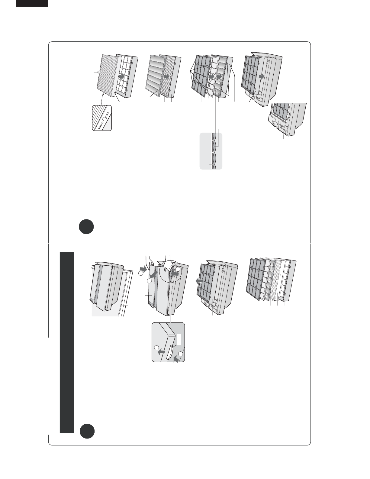
DUST SENSOR
1
Remove the Front
Panel and detach the
Sensor Filter
•DetachtheSensor Filter
while pulling the tab on
the Sensor Cover.
2
Remove any dust
from the Sensor Fil-
ter.
•DetachtheSensorFilter,
andtap itlightlywith your
handto remove thedust.
If it is very dirty, wash it
with water and then al-
low it to dry thoroughly.
3
Insert the Sensor Fil-
ter into the cover, in-
stall it in the Main unit
and attach the Front
Panel.
•TheSensor Filter can be
inserted either way
round.
CAUTION
•Do not forget to reinstall the Sensor Cover before
restarting the unit.
• Do not insert any foreign object into the filter. This
may result in damage or malfunctioning of the unit.
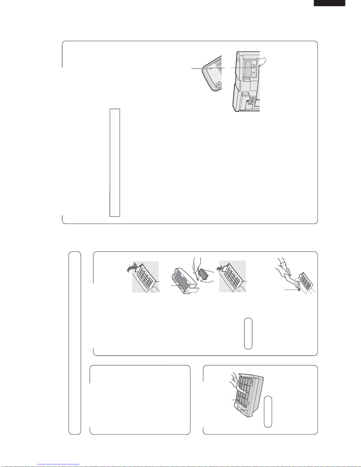
ODOR SENSOR
Remove dust from the sur-
face of the sensor opening
with a vacuum cleaner.
Sensor Cover
Sensor Filter
SensorCover
Sensor
opening
FILTER
CLEANING
Cleanthe top surface ofthePre-
Filter lightly with a vacuum
cleaner.
NOTE
•The HEPA Filter is damaged
easily. Do not bring it into di-
rect contact with the nozzle of
a vacuum cleaner.
Also make sure never to wash
it with water.
• The HEPA Filter and Active
Carbon Filter do not need
cleaning.
Pre-Filter
RESET
FILTER REPLACEMENT GUIDELINES
The filter replacement period is indicated by the Filter Lamp.
(The lamp will light up in about 5 years, when using the unit for 12 hours daily.)
•Theoperationhours are saved in memory even when removing the Power Plug for transpor-
tation to another room, etc.
• The Filter lamp is to be used only as a guide.
• If dust or odors cannot be removed easily, replace the filters.
Guide for replacing the filters
• HEPA Filter About 5 years after opening
• Active Carbon Filter About 5 years after opening
•The replacement period is based on the condition that smoking 10 cigarettes per day and
the dust collection/deodorization ability is reduced by half than that of new filters.
(JEM1467, The Japan Electrical Manufacturers’Association)
•The replacement period differs depending on the operation hours and location of installa-
tion.
•Depending on the usage environment, odor may be noticed from the Air Outlet in several
months. (For understanding the product. Refer to page E-1)
REPLACING THE FILTERS
1
See page E-8 for directions on how to
install the Filters when replacing.
2
Fill in the usage start date of the fil-
ters on the Date Label, which can be
found on upper of the Main unit.
3
Be sure to press the Filter Reset But-
ton on either the Remote Control or
the Main unit with the Power Cord
connected to the outlet. A short beep
will be heard and the operation hours
store in the memory will be reset. The
Filter Lamp will then go out automati-
cally.
(Refer to page E-11)
Replacement filters (Model : FZ-60SEF)
• HEPA Filter: 1 unit
•Active Carbon Filter: 1 unit
Please ask for replacement filters at your dealer of purchase.
Cautions concerning the disposal of filters
Please dispose of replaced filters according to the local disposal laws and regulations.
HEPA Filter materials:
•Filter: Polypropylene
•Frame: Polyester
Active Carbon Filter materials:
•Deodorizer: Activated charcoal
• Net: Polypropylene 60% Polyester 40%
Filter Reset Button

10
FU-60SE-TA
ABOUT THE FUNCTION
1. Auto operation
The airflow volume (Silent / Medium / High) automatically changes to purify the air effectively depending on how dirty
the air detected by the sensor is.
2. Silent operation
It operates quietly with small airflow volume (minimum airflow).
3. Max. operation
It operates with the maximum airflow volume. This is effective when you want to remove the dust and odor in the air
quickly.
4. Pollen operation
After operating in "High" for 10 minutes, it repeats the 20 minute "Medium" operation and the 20 minute "High"
operation. This is effective when pollens are annoying.
5. OFF timer operation
After the set off timer time (1, 4, 8 hours) is passed the operation stops.
6. Clean sign lamp
This detects the contamination conditions of the air for about 30 seconds after inserting the plug. When the operation
is turned "ON" during this time, the clean sign lamp changes from Green
_
Orange
_
Red
_
Orange
_
Green in order. During this period the cluster mode becomes forcibly the clean mode and the cluster lamp lights in
blue. After that the color of the lamp changes depending on the contamination condition of the air detected by the
sensor in the room.
7. Plasmacluster (Cluster ions selection)
Auto........................... The "clean mode"andthe"ion control mode" are changed overdependingonthe contamination
condition (contamination sensor) of the air in the room.
When the clean sign lamp lights in " Green " ... Ion control mode
When the clean sign lamp lights in " Orange " or " Red " ... Clean mode
Clean......................... This always operates in the " Clean mode " (Cluster lamp " Blue " lights on)
In this clean mode positive ( ) and negative ( ) ions are generated in the almost same
proportion and it is effective for reducing same air borne mold.
Ion control ................. This always operates in the " Ion control mode ". (Cluster lamp " Green " lights on)
In the ion control mode negative ( ) ions are generated relatively more and arrange the ion
balance in the room.
OFF........................... This stops the generation of the cluster ions. (Cluster ion lamp off)
8. Safety device
(1)Current fuse
Activates by abnormal electric current [Operating current: 2.5A]

11
FU-60SE-TA
ELECTRIC CIRCUIT
1. Employing lead-free solder
The "Main PWB" of this model employs lead-free solder. This is indicated by the "LF" symbol printed on the PWB
and in the service manual. The suffix letter indicates the alloy type of the solder.
Example:
Indicates lead-free solder of tin, silver and copper.
2. Using lead-free wire solder
When repairing a PWB with the "LF" symbol, only lead-free solder should be used. (Using normal tin/lead alloy solder
may result in cold soldered joints and damage to printed patterns.)
As the melting point of lead-free solder is approximately 40˚C higher than tin/lead alloy solder, it is recommend that
a dedicated bit is used, and that the iron temperature is adjusted accordingly.
3. Soldering
As the melting point of lead-free solder (Sn-Ag-Cu) is higher and has poorer wettability, (flow), to prevent damage
to the land of the PWB, extreme care should be taken not to leave the bit in contact with the PWB for an extended
period of time. Remove the bit as soon as a good flow is achieved. The high content of tin in lead free solder will cause
premature corrosion of the bit. To reduce wear on the bit, reduce the temperature or turn off the iron when it is not
required.
Leaving different types of solder on the bit will cause contamination of the different alloys, which will alter their
characteristics, making good soldering more difficult. It will be necessary to clean and replace bits more often when
using lead-free solder. To reduce bit wear, care should be taken to clean the bit thoroughly after each
use.PRECAUTIONS FOR USING LEAD-FREE SOLDER
WIRING DIAGRAM
SERVICE PARTS
PWB ass'y (CPWB-A028KKKZ)= Power supply PWB + Switch PWB + Control PWB + Light lead guide + LED guide
Dust sensor
Switch PWB ass'y
Control PWB ass'y
Power supply
PWB ass'y
CN-A
CN-D
CN-F
CN-G
WH-B
CN-E
WH-A
Plasmacluster unit
CN-C
Fan
motor AC
220V

12
FU-60SE-TA

13
FU-60SE-TA
(1) Block diagram
(2) Circuit description
1) Noise prevention circuit
This circuit protects the circuit from the external noise and lightning surge coming in from the AC plug, and also
absorbs the noise outgoing from the AC plug. It consists of the film capacitor C1 and C4, varistor VRS1, current
fuse FUSE1, and line filter L1.
2) Power supply circuit
a) Vm: The commercial power supply (AC220V) is put through the current fuse FUSE1 and the thermal fuse,
rectified by the diode bridge DB1, and smoothed by the electrolytic capacitor C2.
Then it is supplied as the power input for the fan motor and the hybrid IC (HIC1).
(Vm = approx. DC311V)
b) VL: The hybrid IC (HIC1) is activated by the DC input Vm and the external coil L2, and has two output
terminals.
The first output is changed into VL after being smoothed by the electrolytic capacitor C12.
It is used as the power supply for the buzzer drive circuit, fan motor drive circuit, relay drive circuit,
and high voltage unit drive SSR1 (VL = approx. DC15V).
c) VDD: The second output is smoothed by the electrolytic capacitor C11 before used as the power supply for
the microcomputer LSI-1, high-voltage unit drive circuit, relay drive circuit, dust/odour sensor circuits,
and LED drive circuit (VDD = approx. DC5V).
3) Power supply clock generation circuit
The voltage between the input terminal to DB1 and its output terminal (GND) is divided by the resistor R21, R22
and R23, and input into the digital transistor Q21.
Then it is converted into the DC square wave signal that has the same frequency with the AC power supply, and
input into the pin 31 on the microcomputer LSI1 via the resistor R25 and the ceramosonic capacitor C22.
The microcomputer LSI-1 considers it as the source signal for time count, and decides the power supply
frequency and controls the output time.
When this signal retains " H " or " L " state for over certain period of time, the microcomputer LSI-1 assumes it
to be a power failure and stops outputs from the fan motor, high-voltage unit, dust/odour sensors, buzzer, and
LED.
4) Reset circuit
If the VDD is lower than specified, " L " is input into the pin 18 of the microcomputer LSI1 to reset LSI-1 using
the circuit consisting of the reset IC (IC2), R31 and C32.
When VDD is higher than specified, " H " is input into the same pin, reset command is canceled, and LSI-1
is started.
Fan mootor
drive circuit
Noise preven-
tion
circuit
Key
input circuit
Remote control
recieve circuit
Exchange operate
drive circuit
LED
drive circuit
Clock circuit
Power supply
circuit
Clock generation
circuit
Power supply
Reset circuit
High voltage
unit drive circuit
High voltage unit
Relay drive
circuit
Buzzer drive
circuit
Dust sensor
circuit
Odor sensor
circuit EEPROM
circuit
LSI 1 (Microcomputer)
(Plasma
cluster unit)

14
FU-60SE-TA
5) Clock circuit
This generates the clock signal required for operation of the microcomputer LSI-1.
Its frequency is 4MHz which is supplied from the ceramic oscillator CF1.
6) Key input circuit
The key SW1 on the switch PWB K is connected to the resistor R101.
The key status is input into the pin 7 of the microcomputer LSI-1 via the resistor R102 and the ceramosonic
capacitor C101. Key ON : H, Key OFF : L
7) LED drive circuit
Repetitive signal of " H " and " L " output from the pins 3 - 5 of the microcomputer LSI-1 turns on and off the digital
transistors Q110 - Q112.
They are turned on one by one at intervals of certain time. When " L " is output from the pins 11 - 16 of the
microcomputer LSI1 as they are turned on, the corresponding LED that are connected to them light up.
The LED to display the cluster mode has two colors of super-high-intensity green and blue.
When in the clean mode, " L " is output from the pin 10 of he microcomputer LSI1, Q114 is turned on, and the blue
LED lights up. When in the refresh mode, " L " is output from the pin 9, Q113 is turned on, and the green LED lights
up.
8) Remote control recieve circuit
The infrared signal transmitted from the remote control is received by the reception unit RU1.
When the H/L signal is input into the pin 8 of the microcomputer LSI-1 via the resistor R81 and the ceramosonic
capacitor C83, it is determined from which key the signal was transmitted. C81, C82, and C83 absorb or reduce the
disturbing lights, noise derived from its own power supply circuit, and external noise.
9) Dust sensor circuit
When the pulse signal, which is the dust sensor drive signal, is output from the pin 35 of the microcomputer LSI-1
(input into the pin 3 of the sensor connector CN-F), the dust sensor is activated and the sensor output signal (pin
2 of the sensor connector CN-F) is input into the pin 30 of the microcomputer (A/D conversion terminal) via R62 and
C63.
< Principle of dust sensor >
Using the pulse signal input from the microcomputer, the infrared LED inside the dust sensor emits light.
When the light is reflected by the dust that passes through the sensor, it is detected by the internal photo
acceptance unit and amplified, and then output from the terminal.
Less dust: less light acceptance
_
less output (low voltage)
More dust: more light acceptance
_
more output (high voltage)
< Control >
After turning the power on, the value obtained 20 seconds after starting the first operation (for 30 seconds, the clean
sign of three colors for stabilization is lit one by one) is compared to the initial setting reference value of the
microcomputer.
If it is clean enough, the reference value is revised, and if it is dirtier than the designated level, the clean sign is
changed to the sign that indicates the air is contaminated (orange or red, depending on the level), while the
reference value remains the same.
The value is compared with the reference value in the previous operation and is controlled 20 seconds or more after
the operation is started.
The dust sensor is always activated during operation, and air contamination is checked in every four seconds in
relative comparison between the average value and the reference value.
The clean sign is displayed, the fan motor is controlled or the cluster mode is switched according to the level of
contamination.
Reference value: If the current level is cleaner
_
the reference valueis is changed to the current value
than the reference value immediately.
: If the current level is dirtier
_
the value remains the same.
than the reference value
_
the reference value is revised when the level becomes
cleaner than that.
The dust sensor is activated only during the operation.
It is deactivated while the operation is stopped to cut down the standby power consumption.
Luminescence sideReceiver
The hole through
which dust passes

15
FU-60SE-TA
10) Odour sensor circuit
The pulse signal, which is the odour sensor drive signal, is output from the pin 37 of the microcomputer LSI1, and
the odour sensor is pulse-driven on the circuit of Q71, Q72, R73, R74, R76, and C73.
The sensor output signal is input into the pin 27 (A/D conversion terminal) of the microcomputer via R71 and C71.
< Principle of odour sensor >
The metal oxide semiconductor in this sensor reacts to ammonia, hydrogen, and alcohol, and changes the
resistance. Weak odour : high resistance
_
high voltage
Strong odour : low resistance
_
low voltage
< Control >
After turning the power on, the value obtained 25 seconds after starting the first operation (for 30 seconds, the clean
sign of three colors for stabilization is lit one by one) is set as the reference value and the contamination is decided
in relative comparison between the values detected at an interval of approximately one second and the reference
value.
According to the contamination level, the clean sign is displayed, the fan motor is controlled, or the cluster mode is
switched.
Although the odour sensor is always activated during operation, it is deactivated while the operation is stopped to
cut down the standby power consumption.
However, if it comes to a complete stop, the readingcondition is altered in the next operation.
Therefore, it is activated for one minute in every ten minutes to keep the operating conditions.
Reference value: if the current level is cleaner than the reference value
_
the reference value is changed to the
current value immediately.
If the current level is dirtier than the reference value and the contamination level changes
(such as suddenly increased odour of cigarette smoke)
_
the reference value remains the same, but the clean sign is changed to indicate the air is contaminated
(orange or red, depending on the level).
_
the value in the clean condition (green) is adopted as a new reference value.
If the current level is dirtier than the reference value and the contamination level does not change
(Natural change only)
_
the reference value remains the same.
_
the value in the cleanest condition at eight-minute intervals is adopted as a new reference value.
11) Buzzer drive circuit
The " H " / " L " signals output from the pin 34 of the microcomputer LSI1 drive the digital transistor Q51 and sound
the buzzer BZ1.
12) Fan motor drive circuit
The fan motor has four input terminals and one output terminal.
Vm : DC voltage input to be the source of motor rotation. (Vm = approx. DC311V)
(CN-C7 pin) Vm created by the power supply circuit is directly input and is constantly applied.
GND : Reference of the electric potential. All potentials such as Vm, Vcc, Vs, and PG indicate the
(CN-C5 pin) potential differences with GND.
Vcc : DC voltage input terminal to be the power supply for the circuit that is built in the fan motor.
(CN-C3 pin) During operation, it turns on Q43 and Q44 by outputting the " H " signal from the pin 33 of
the microcomputer LSI1 of the fan motor, and supplies the potential almost equal to VL to the
Vcc terminal (Vcc = approx. DC15V).
Vs : This input terminal controls the revolution speed of the fan motor (speedinstruction signal).
(CN-C2 pin) After supplying Vcc during operation, the PWM (x/256µs) pulse is output from the pin 6 of the
microcomputer LSI-1 and smoothed in the circuit consisting of C41, R41-43, Q41 and Q42.
Then it goes through R46 and C43 to supply the DC voltage to the Vs terminal.
(Vs = approx. DC0 ~ 6V)
When speeding up revolution: the pulse width X is widened
_
Vs voltage is increased
When slowing down revolution: the pulse width X is narrowed
_
Vs voltage is decreased
PG : Fan motor revolution speed output terminal (feedback signal)
(CN-C1 pin) The pulse signal according to the revolution speed is output and it is input into the pin 32 of the
microcomputer LSI1 via the circuit consisting of R47, R44, R45, and C42.
The microcomputer recognizes the current revolution speed based on this PG signal, and
controls the Vs signal above to keep the speed to the designated level.

16
FU-60SE-TA
13) Plasmacluster unit drive circuit
The plasmacluster unit is the power supply unit that supplies the high voltage to generate ion from the cluster
electrode, and it can be activated by inputting AC220V into it.
When the solid state relay SSR1 is turned on, the voltage for commercial power supply drops in the resistor R0 and
approximately AC90 ~ 110V is applied to the plasmacluster unit.
During operation, it outputs " L " / " H " from the pin 25 of the microcomputer LSI-1, turns on and off Q122 and Q123,
and controls and drives SSR1.
14) Relay drive circuit
This is a circuit that shall be operated by changing a relay switch for CLEAN / ION CONTROL in plasmacluster unit.
In clean mode : " H " is output from the pin 40 of the microcomputer LSI-1 and RY is turned off.
In cluster automatic operation ............. It enters the clean mode when the clean sign indicates
the air is contaminated (orange or red).
In ion : It outputs " L " from the pin 40 of the microcomputer LSI-1, turns on RY, and bypasses one side
control mode of the cluster electrode and one side of the AC input of the high-voltage unit to direct the flow of
electron in one way, thus generating minus ion in large volume compared to plus ion.
In cluster automatic operation ............. It enters the refresh mode when the clean sign
indicates the air is clean (green).
15) EEPROM circuit
During operation, data integrated with the operation time of the fan motor (dirtiness of the filter) is read and written
into EEPROM (IC1) using the repetitive signals of " H " and " L " that are input and output from the pins 1
and 2 of the microcomputer LSI-1.
SPECIFIC MODEL LIST
Some of them are not used for servicing however specified for reference.
(1) Test mode
(1) Outline
The test mode is a mode to test nonconformance of the circuit PWB, etc., and used for inspection, etc. at the
time of mass production.
(2) Setting method
When turning on the power while pressing the [Filter reset button] of the main body, the buzzer sounds
"peep" and enters the "test mode".
(3) Canceling method
In all test modes, when pressing the [Operation ON/OFF button] on the remote controller, the buzzer sounds
"peep" and the "test mode" is canceled and becomes the initial state at normal halt.

17
FU-60SE-TA
The clean sign lamp "Orange" lights on.
The clean sign lamp "Red" lights on.
LED
PWB ASSEMBLY
No.
PORT No.
25 40 35,37 9 8 7 4 5 6 10 11 3 2 1 13, 14 15,16 LED No.
1
2
3
(Lo)
(Lo)
(Lo)
(Lo)
(Lo)
(Lo)
(Lo)
(Lo)
(Lo)
(Lo)
4
5
6
7
8
9
10
11
12
Check the voltage : VDD = 5V±0.3V
Error display list No.
Reference
1
2
3
4
1
2Error display, symptom
Buzzer
ClusterClean sign
OFF timerOperation mode
Fan
Silent Quick Drive Mode
Custer
Sensor
Operation
Odor
Dust
Filter Auto
Red Green Green Green Green Green GreenGreen
1 hours 4 hours 8 hours
Green Green Orange Red GreenBLueYellow
Silent Med. High Quick Pollen Original
Turn the power on while holding
down the " FILTER RESET "
button on themain unit.
Press the " ON/OFF " button on
the main unit.
Press the "
Filter reset
" button
on the
main unit.
Press the " Auto" button on the
remote control.
Press the " Manual " button on
the remote control.
Press the " Pollen " button on
the remote control.
Remove the cluster unit.
Insert a stick from the window of
the dust sensor.
Power OFF
Point to be check
: ON, : Flashing, : Pip sound: ON or OFF,
Model select, sensitivity select, original select check (Indication differs depending on the model.)
The original select is displayed with these 4 LEDs.
EEPROM version No. check (Indication differs depending on the model.)
The version No. of EEPROM is displayed with these
6 LEDs. (Binary digit)
Fan motor rotation speed check (Indication differs depending on the model.)
The rotation speed of the fan motor (Quick) is displayed with these 8 LEDs. (Binary digit)
Fan motor rotation speed indication
Connect the cluster unit. Press the
"OFF timer" of the remote controller.
Blow gas to the Gas sensor.
After pressing the "Operation ON/OFF" key on the remote
controller, press the "Filter reset" key on the remote controller.
In case of Quick: OFF, Pollen: lighting,
set the sensitivity select to "Normal".
(No original specification = 0000)
Check the version No. of EEPROM.
(Version No. 21 = 010101)
Check the rotation speed of the fan
motor (rapid).
OK if in the range of ±1 in binary digit.
Check the cluster error input.
The clean sign lamp "Green" lights on after
10 seconds has passed from the start of
item 2.
Concerned item No.
Item 2
Item 2
Item 3 and after
All items
The clean sign flickers in Red, operation impossible
The clean sign flickers in Green, operation impossible
The blue cluster lamp flickers, buzzer intermittent sound, operation impossible.
Silent lamp flickers.
EEPROM communication error
EEPROM checksum error
Cluster error
Fan motor rotation speed error
Error contents Probable cause
EEPROM circuit failure, EEPROM failure
Wrong EEPROM data
Cluster error input circuit failure
Fan motor circuit failure

18
FU-60SE-TA
Measurement of power consumption
While in the test mode, the power consumption is measured.
It is stopped and finished by pressing the Operation ON/OFF button.
Error table
No. Item Error display/status Cause Solution
1 No. 1 Clean sign is flashing. EEPROM communication Replace the circuit PWB.
2
No.1 - No.10
Silent lamp is flashing. Fan motor revolution speed Replace the fan motor.
Check the insertion of the
fan motor connector.
(2) Demo mode
1) Outline ............................. The demo mode (display mode) is used for demonstration of displays in shops.
2) Setting procedure .................. While operating in the pollen mode, press the " Operation selector/OFF " button
to stop the operation, and hold it down for three seconds or more.
When the " Pollen " button on the remote control is pressed while holding it
down, a pip sound is heard and the unit starts the demo mode.
3) Cancellation procedure.......... While holding down the " Operation selector/OFF " button for three seconds or
more, press the " Pollen " button.
A bleep sound is heard and the demo mode is canceled, and the unit is stopped
in the normal mode.
4) Switch operation .................... Only the demo mode canceling operation is enabled.
5) LED indicator ......................... (a) Clean sign : Undetected mode is displayed (as described below).
(b) Cluster lamp : The blue and green LEDs are lit alternately at one-
second intervals (as described below).
(c) Others : Lit and distinguished as shown in the table below at
one-second intervals.
6) Load output............................ (a) Odour sensor drive output :
equivalent intermittent output with the normal stop
(b) Other outputs :
OFF
(3) Aging mode
1) Outline ............................. In this mode, several operation modes can be repeated automatically to perform
life test of loads, materials, and driving equipment.
2) Setting procedure .................. Turn the power on while holding down the " Operation selector/OFF" button on
he main unit. While pressing it down, press the " Manual" button within five
seconds. A bleep sound is heard and the unit starts the aging mode.
3) Cancellation procedure.......... It can be canceled only by cutting the power supply.
4) LED indicator ......................... (a) Timer lamp : " 1 hour " and " 8 hours " are always lit (mode display).
(b) Others: Same as the normal mode.
5) Operation ............................. (a) Programmed operation in the following sequence.
1
Green
Orange
Red
Orange
Blue Green Blue Green Green
Blue
Orange
Green Red
Blue
Orange
Green
Demo mode display No.
Clean sign
Cluster lamp
Operation mode lamp
Auto
Silent
Medium
High
Max.
Pollen
Note [The contents of a display]
2345678
: ON : OFF
Max.
Aging mode
injection
after 10 min. after 10 min.
after 10 min.
Clean mode
Silent
Ion control
Under a stop
Ion off

19
FU-60SE-TA
6) Switch operation ... ................ (a) On the main unit: All disabled.
(b) On the remote control: All disabled.
7) Abnormal mode detection ...... (a) Enabled. When the abnormal mode is activated, it can be canceled with the
"Operation selector/OFF " button on the main unit.
When it is canceled, the aging mode operation is restarted from the
beginning.
5. Abnormal checking mode
(1) Outline
In the abnormal checking mode, the unit detects abnormality or defects of the main unit or circuits with various
sensors, and controls loads and displays abnormalities according to the problem.
(2) Abnormal revolution speed of the fan motor
1) Outline .................................... This mode is activated when the unit detects that the fan motor is locked or
the is opened.
2) Detection time ........................ In all modes during operation
3) Detection conditions .............. When the unit detects [0 rpm] as the revolution speed of the fan motor for 15
consecutive seconds.
4) Abnormality display ............... Only the " silent lamp " flashes in a one-second cycle.
All other LEDs are turned off.
5) Loads control ......................... All loads are immediately turned off and the operation will stop.
6) Cancellation .......................... The abnormal mode can be cancelled by pressing the "Operation selector/
OFF" button on the main unit or the " ON/OFF " button on the remote control.
However, with the problem unsolved, the unit enters the same abnormal
mode even if you turn on the unit again.
(3) EEPROM error
(1) Outline
Error mode to act when "communication error" or "checksum error" is issued in EEPROM reading when
turning on the power.
(2) Detecting time
Immediately after turning on the power
(3) Detecting condition
When "communication error" or "checksum error" is detected in EEPROM reading when turning on the
power.
(4) Error display
Only the "automatic lamp" flickers in 1 second cycle. All the other LEDs are off.
(5) Switch operation
All the switch operation is invalid. However settings of specific modes other than demonstration mode, aging
mode are valid.
(6) Load action
All the loads are OFF. The buzzer does not sound.
(7) Canceling method
Cannot be canceled unless the power plug is pulled out.
(4) Cluster error
(1) Outline
Error mode to detect the connector open of the cluster unit. This is not directly to detect the presence or
absence of generation of ions or high tension output. When this error mode acts, the cluster high tension
drive output stops and the error is displayed (cluster ion lamp "blue" flickers) however other operations are
possible.
(2) Detecting time
In case that all of the cluster high tension drive outputs do not duty control but all ON during operation other
than ion mode "OFF". (During "High" or "Max." operation)
(3) Judging method
When the monitor output of the cluster unit becomes 0.2 V or less continuously for 10 seconds or more.
(4) Error display
The "blue of the cluster ion lamp" flickers in 1 second cycle. Other LEDs keep normal display.
(5) Load action
The cluster high tension drive output is immediately turned OFF. The load outputs other than that keep
normal operation.
(6) Canceling method
After removing the cause of the error, turn "ON" the power again or turn "ON" the ion mode. That is, manual
recovery but not automatic recovery.

20
FU-60SE-TA
NOTE:
1. Unspecified diode is VHD1SS270A/-2.
2. Unspecified capacittor is VCKYD21CY103N(16V, 0.01µF).
3. Parts in parentheses are not used.
Cluster
Cluster
Silent
Medium
8H
4H
1H
Auto
Filter
Original
Pollen
Filter reset
Red
Red
Green
Green
Clean sign
Clean sign
Quick
High
OPERATION ON/OFF
Auto Silent Medium High Max Pollen
Clean sign
Slide SW Filter reset SW
(Original)
Cluster LEDCluster LED 148
Display out line
Deodozation filter
Control panel
Operation ON/OFF
Plasmacluster unit
Dust sensor
220 ~ 240V
AC
Table of contents
Other Sharp Air Cleaner manuals

Sharp
Sharp FZ-28SEF User manual

Sharp
Sharp Plasmacluster FU-W25AW User manual

Sharp
Sharp Plasmacluster KC-C100U User manual

Sharp
Sharp UA-KIN50E User manual

Sharp
Sharp KC-860EKW User manual

Sharp
Sharp IG-EX20B User manual

Sharp
Sharp FP-GM50Y User manual

Sharp
Sharp QNET ZENsational KC-G60M-W User manual

Sharp
Sharp KC-A60Y User manual

Sharp
Sharp Plasmacluster KC-860U User manual

Sharp
Sharp FP-J30E User manual

Sharp
Sharp FZ-550CF User manual

Sharp
Sharp FP-K50UW User manual

Sharp
Sharp FP-JM30E User manual

Sharp
Sharp FP-G50E User manual

Sharp
Sharp FZ-80SEF User manual

Sharp
Sharp FZ-WS50SFE User manual

Sharp
Sharp Plasmacluster KC-C150U User manual

Sharp
Sharp FP-K50U User manual

Sharp
Sharp FX-J80J User manual