Sharp AR-RP6 User manual

CODE : 00Z
qSERVICE MANUAL
CONTENTS
Parts marked with "!" are important for maintaining the safety of the set. Be sure to replace these parts with specified
ones for maintaining the safety and performance of the set.
SHARP CORPORATION This document has been published to be used
for after sales service only.
The contents are subject to change withoutnotice.
ARSP6//A1E
Digital copier
Reverse Single
Pass Feeder (RSPF)
Single Pass Feeder (SPF)
AR-RP6
MODEL AR-SP6
[1] PRODUCT OUTLINE . . . . . . . . . . . . . . . . . . . . . . . . . . . . . . . . . . 1
[2] SPECIFICATIONS . . . . . . . . . . . . . . . . . . . . . . . . . . . . . . . . . . . . 1
[3] UNPACKING AND INSTALLATION . . . . . . . . . . . . . . . . . . . . . . . 1
[4] EXTERNAL VIEW AND INTERNAL STRUCTURE . . . . . . . . . . . 4
[5] OPEREATIONAL DESCRIPTIONS . . . . . . . . . . . . . . . . . . . . . . . 5
[6] ADJUSTMENTS . . . . . . . . . . . . . . . . . . . . . . . . . . . . . . . . . . . . . . 7
[7] DISASSEMBLY AND ASSEMBLY . . . . . . . . . . . . . . . . . . . . . . . . 8
[8] MAINTENANCE . . . . . . . . . . . . . . . . . . . . . . . . . . . . . . . . . . . . . 14
[9] ELECTRICAL SECTION. . . . . . . . . . . . . . . . . . . . . . . . . . . . . . . 15

AR-SP6/RP6 PRODUCT OUTLINE
– 1 –
[1] PRODUCT OUTLINE
This machine is a duplex document auto feeder attached to a digital
copier.
It feeds originals automatically to allow continuous copying.
[2] SPECIFICATIONS
[3] UNPACKING AND INSTALLATION
1. Unpacking
For unpacking, refer to the figure below.
2. Installation
Turn the main switch of the copier to the “OFF” position and then
remove the power plug of the copier from the outlet.
1. Remove the document cover.
Lift the document cover from the copier and tilt it to the rear side to
remove it.
AR-RP6 AR-SP6
Document set direction Face up
Document set position Right/Center reference
Document transport
system Sheet through type
Document feed sequence Top take-up feed
Document size AB series: A3 ~ A5
Inch series: 11 x 17 ~ 8.5 x 5.5
Document weight 56 ~ 90g/m2, 15 ~ 24lbs
Document set quantity Max. 40 sheets (Stack range: within 4mm)
(90g/m2: Set capacity = 30 sheets)
Dimensions 583mm (W) x 435mm (D) x 133mm (H)
Weight About 5.4 kg About 5.0 kg
Power source Supplied from the
copier. (DC 24V) Supplied from the
copier. (DC 24V, 5V)
Power consumption 26.4W 21W
Document size detection On the document feed tray
Detection size Japan: A3, B4, A4, A4R, B5, B5R,
A5
Inch series: 11 x 17, 8.5 x 14, 8.5 x 11,
8.5 x 11R, 8.5 x 5.5
EX AB series: A3, B4, A4, A4R, A5, B5,
B5R, A5R
Mixture of different
document sizes Mixture paper feed: Not available
Random paper feed: Not available
Document reverse Allowed
(without 8.5 x 5.5) Not allowed
Display section (LED) None
Document exchange
speed S 3S, 16 sheets/min (AR-160M)
S 3S, 20 sheets/min (AR-200M)

AR-SP6/RP6 UNPACKING AND INSTALLATION
– 2 –
2. Remove the right cabinet.
Remove the screws and remove the right cabinet.
3. Remove the document glass and the right document
glass holder.
Remove the screws, remove the document glass from the copier, and
then remove the right document glass holder.
4. Attach the SPF glass holder.
Fit the SPF glass holder to the document glass.
Attach the document glass to the copier and fix it with the screws.
5. Attach the right cabinet.
Reattach the right cabinet to its original position and fix it with the
screws.
6. Cut out the cut-out portion.
Cut out the cut-out portion of the rear cabinet with nippers or the like.
At this time, be careful about the orientation of the nippers so that the
cut plane of the rear cabinet is flat.
7. Attach the automatic document feeder.
Insert the hinge portions of the document feeder into the mounting por-
tions of the copier by holding the feeder at an angle toward the rear
side.

AR-SP6/RP6 UNPACKING AND INSTALLATION
– 3 –
8. Connect the relay connector.
Connect the harness of the automatic document feeder to the connec-
tor of the copier and tighten the screws on the connector.
9. Remove the filament tape.
Remove the filament tape located in the positions shown in the illustra-
tion.
10. Attach the intermediate tray. (AR-RP6 only)
Insert the intermediate tray all the way into the document feeder.
Insert the power plug of the copier to the outlet and turn on
the main switch of the copier.
11. Adjust the white compensation pixels.
• Open the automatic document feeder, execute simulation 63-7 refer-
ring to the service manual, and adjust the automatic white compensa-
tion pixels of the document feeder.
12. Check the copy magnification ratio.
• Set an original on the document glass and copy it.
Then, set an original in the document feeder tray and copy it.
• If the magnification ratio of the copy from the document feeder is dif-
ferent from that of the copy from the document glass, execute simula-
tion 48-5 to carry out adjustment referring to the service manual.
13. Check the center displacement.
• Set an original on the document glass and copy it.
Then, set an original in the document feeder tray and copy it.
• If the center of the copy image from the document feeder is different
from that of the copy image from the document glass, execute simu-
lation 50-12 to carry out adjustment referring to the service manual.
14. Check the top end position.
• Set an original on the document glass and copy it.
Then, set an original in the document feeder tray and copy it.
• If the top end position of the copy image from the document feeder is
different from that of the copy image from the document glass, exe-
cute simulation 50-06 to carry out adjustment referring to the service
manual.

AR-SP6/RP6 EXTERNAL VIEW AND INTERNAL STRUCTURE
– 4 –
[4] EXTERNAL VIEW AND INTERNAL STRUCTURE
1. External view
2. Internal structure
Sensor, detector, etc.
No. Name
1 Document set tray
2 Document guide
3 Document feed section cover
4 Document transport section cover
5 Document exit section
12
3
4
5
6
7
9
8
10
11
12
13
14
15 16
No. Code Name Type Function/Operation Note
1 W0 Document set sensor Photo transmission Detects presence of documents.
2 COVER Open/close sensor Photo transmission Detects open/close of the paper feed unit.
3 W1 Document width sensor (A4R, LTR, A5) Photo transmission Detects the document width on the tray.
4 W2 Document width sensor (B4, B5) Photo transmission Detects the document width on the tray.
5 W3 Document width sensor (WL, TR, A5R, A4, LT) Photo transmission Detects the document width on the tray.
6 PSOL Pickup solenoid — —
7 PAPER Paper entry sensor Photo transmission Detects presence of documents.
8 RSOL Pressure release solenoid — — AR-RP6 only
9 CLH Transport clutch — —
10 MOT SPF (RSPF) motor Stepping motor Drives document feed on the tray, trans-
port, and paper exit roller.
11 GSOL Gate solenoid — — AR-RP6 only
12 — Interface PWB — —
13 L1 Document length detection SW (Short) Photo transmission Detects the document length on the tray.
14 L2 Document length detection SW (Long) Photo transmission Detects the document length on the tray.
15 COVER OPEN Book sensor Photo transmission Detects the SPF (RSPF) float.
16 PO Paper exit sensor Photo transmission Detects presence of documents.

AR-SP6/RP6 OPEREATIONAL DESCRIPTIONS
– 5 –
[5] OPEREATIONAL DESCRIPTIONS
1. Major parts of the paper feed section 2. Out line of operations
■AR-RP6 (RSPF)
[Duplex documents]
1) Document set (Document set sensor ON)
4
2) Document size detection (Document width sensors W1, W2, W3
detect the document width, and docu-
ment length sensors L1, L2 detect the
document length.)
4
3) Copier COPY key ON
4
4) RSPF motor ON
4
5) Pickup solenoid ON
4
6) Pickup roller and paper feed roller rotation
4
7) Paper entry sensor detects the document presence.
4
8) PS roller rotation
4
9) Copying (Front surface of document)
4
10) Transport roller rotation
4
11) Paper exit roller rotation
4
12) Paper exit gate falls down.
(Documents are discharged to the intermediate tray.)
4
13) Reverse gate falls down.
4
14) Paper exit roller reverse rotation
(Documents are fed to the reverse path.)
4
15) Paper entry sensor detects document presence.
4
16) PS roller rotation
4
17) Copying (Back surface of document)
4
18) Transport roller rotation
4
19) Paper exit roller rotation
4
20) Paper exit gate falls down
(Documents are discharged to the intermediate tray.)
4
21) Reverse gate falls down.
4
22) Paper exit roller reverse rotation
(Documents are fed to the reverse path.)
4
23) Paper entry sensor detects document presence.
4
24) PS roller rotation
4
25) Paper exit roller rotation
4
26) Paper exit gate lifts up.
4
27) Documents are fed to the paper exit tray.
4
28) Next document 3(YES) 3Go to 4).
4 (NO)
29) RSPF motor OFF
No. Part name Operation Note
1 Document length
sensor (L2) Detects the document length
on the tray.
2 Document length
sensor (L1) Detects the document length
on the tray.
3 Document set
sensor (W0) Detects presence of docu-
ments.
4 Document width
sensor (W1, W2, W3) Detects the document width.
5 Pickup roller Picks up documents.
6 Paper feed roller Feeds and transports docu-
ments.
7 Paper entry sensor
(PAPER) Detects transport of docu-
ments.
8 PS roller Makes synchronization
between the document lead
edge and the image lead edge.
9 PS follower roller Makes synchronization
between the document lead
edge and the image lead edge.
10 Transport roller Transports documents.
11 Transport follower
roller Transports documents.
12 Paper exit sensor
(PO) Detects transport of docu-
ments.
13 Paper exit follower
roller Discharges documents.
14 Paper exit roller Discharges documents.
15 Reverse gate Opens/closes the document
reverse path.
16 Paper exit gate Separate document exit to the
intermediate or the paper exit
tray.
AR-RP6
only
17 Intermediate tray Discharges documents to the
intermediate tray during docu-
ment reverse.
AR-RP6
only
1 2 3,4 5 6 7 8
910111314 151617 12

AR-SP6/RP6 OPEREATIONAL DESCRIPTIONS
– 6 –
■AR-SP6 (SPF) 3. Document size detection
1) Document size detection with the document set tray
When documents are set on the document set tray in the auto selection
mode of paper/copy magnification ratio, the document size is detected
and paper and the copy magnification ratio are automatically selected.
When different sizes of documents are set, the max. size is detected.
The document width is detected by the document width sensors (W1,
W2, W3), and the document length is detected by the document length
sensors (L1, L2) to identify the document size. Judgement of the docu-
ment size is made in a certain timing after detecting the document with
the document set sensor (W0).
Note: Detection sensor ON: o, OFF: n
1) Document set (Document set sensor ON)
4
2) Document size detection (Document width sensors W1,
W2, W3 detect the document
width, and document length sen-
sors L1, L2 detect the document
length.)
4
3) Copier COPY key ON
4
4) SPF motor ON
4
5) Pickup solenoid ON
4
6) Pickup roller and paper feed roller rotation
4
7) Paper entry sensor detects the document presence.
4
8) PS roller rotation
4
9) Copying (Front surface of document)
4
10) Transport roller rotation
4
11) Paper exit roller rotation
4
12) Documents are fed to the paper exit tray.
4
13) Next document 3(YES) 3Go to 4).
4 (NO)
14) SPF motor OFF Document set
size and set
direction
Document width sensor Document
length sensor
W1 W2 W3 L1 L2
AB series
A5 onnnn
B5 oonnn
A5R nnnnn
A4 ooonn
B5R nnnon
A4R onnon
8.5” x 13” onnoo
B4 onnoo
A3 ooooo
Inch
series
8.5” x 5.5” onnnn
8.5” x 5.5”R nnnnn
11” x 8.5” ooonn
11” x 8.5”R onnon
8.5” x 13” onnoo
8.5” x 14” onnoo
11” x 17” ooooo

AR-SP6/RP6 ADJUSTMENTS
– 7 –
[6] ADJUSTMENTS
(1) Auto white correction pixel adjustment
[Function]
The white correction start pixel position is automatically adjusted.
This adjustment is performed after the lens unit is replaced.
[Operation]
(2) Magnification ratio adjustment
Note: • When performing this adjustment, check that the CCD unit is
properly installed.
• When performing this adjustment, check that the OC mode
adjustment in copying is completed.
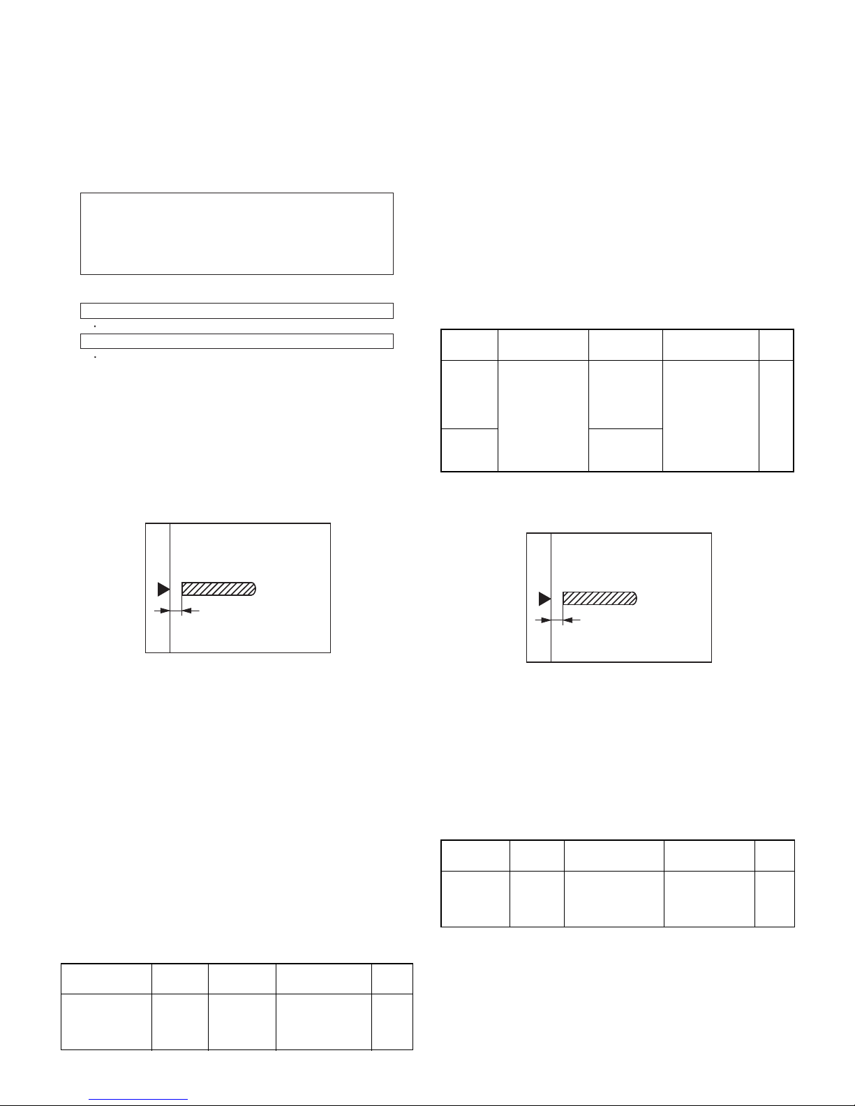
1) Place a scale on the document table as shown below, and make a
normal copy to make a test chart.
2) Set the test chart to the SPF (RSPF) and make a normal copy.
3) Compare the copy and the test chart.
If an adjustment is needed, perform the following procedures.
4) Execute SIM 48-5.
5) The current correction value is displayed on the display section in
two digits.
6) Enter the set value, and press the START key.
The entered correction value is stored and a copy is made.
7) Change the TEXT mode.
The TEXT lamp lights up, and the current correction value of the
back surface sub scanning direction magnification ratio is displayed
on the display section in two digits.
8) Enter the set value, and press the START key.
The entered correction value is stored and a copy is made.
<Adjustment specifications>
(3) Document off center adjustment
Note: When performing this adjustment, check that the paper off-cen-
ter is properly adjusted.
1) Set the center position adjustment test chart (made by yourself) on
the SPF (RSPF).
<Adjustment specifications>
Draw a line in the center of paper. (In the scanning direction)
2) Make a normal copy from the manual feed tray, and compare the
copy and the test chart.
If an adjustment is required, perform the following procedures.
3) Execute SIM 50-12.
4) The current off-center adjustment value is displayed on the display
section in two digits.
5) Enter the set value and press the START key.
The entered correction value is started and a copy is made.
<Adjustment specifications>
(4) Image lead edge position adjustment
1) Set a scale on the OC table as shown below.
2) Make a copy, and use the copied paper as the document and make
a copy from SPF (RSPF) again.
3) Check the copied paper. If an adjustment is required, perform the
following procedures.
4) Execute SIM 50-6.
5) Set the SPF/RSPF lead edge position set value so that the image
similar to the adjusted image at the OC image lead edge position
described previously is printed.
<Adjustment specifications>
Mode Spec SIM Set value Set
range
Magnification
ratio adjustment Normal:
m1.0% SIM 48-5
AE: Surface
TEXT: Back
Add 1:
0.1% increase
Reduce 1:
0.1% decrease
1 ~ 99
During execution,"EXEC" is highlighted
Open the SPF (RSPF) unit and press the [OK] key.
7-segment indicates the order number of the pixel of the white sheet for SPF (RSPF)
exposure correction in the SPF (RSPF) position.
It will display on 7-segment, if values are 93-299, and data are written into the EEPROM.
It will display on 7-segment, it values are 0-92 or 230-999, and data are not written into
the EEPROM.
It will display "--" on 7-segment, it values is 1000 or larger, and data are not written into
the EEPROM..
The SPF white correction start pixel = Displayed pixel position - 34
If the simulation is executed with the SPF unit closed, an error is resulted.
[CA] key: Cancels the test command.
[Interruption] key: Shifts to the sub code entry menu.
Interruption is inhibited during execution.
Note: Since the printed paper is used as the test chart,
place the scale in parallel to both sides.
Mode Specification SIM Set value Set
range
Document
off-center
(AR-RP6)
Simplex:
Center
m
3.0mm
Duplex:
Center
m
3.5mm
SIM 50-12
TEXT:
SPF surface
PHOTO:
SPF back
Add 1:
0.1mm shifted to
R side.
Reduce 1:
0.1mm shifted to
L side.
1 ~ 99
Document
off-center
(AR-SP6)
AE: Surface
TEXT: Back
Adjustment
mode SIM Set value Specification Set
range
Image
lead edge
position
SIM 50-6 1step: 0.1mm shift Lead edge void:
1 ~ 4mm
Image loss:
3mm or less
1 ~ 99
Note: Since the printed paper is used as the test chart,
place the scale in parallel to both sides.

AR-SP6/RP6 DISASSEMBLY AND ASSEMBLY
– 8 –
[7] DISASSEMBLY AND ASSEMBLY
1. External fitting section
Note: Turn the paw in the arrow direction.
2. Paper feed unit section
1) Paper feed unit
2) Document feed section cover
3) Sensor PWB
1
2
2
3
2
1
1
1
3
2
2
4

AR-SP6/RP6 DISASSEMBLY AND ASSEMBLY
– 9 –
4) Pickup solenoid
Note: Remove section A of the pickup solenoid from the solenoid arm
groove.
When assembling, adjust the spacing between the clutch latch
and sleeve with the pick-up solenoid pulled. The size should be
the distance from the tip of the clutch latch and the root of the
clutch sleeve latch.
5) Clutch gear ass’y
6) Pickup roller ass’y
Note: When assembling the pickup roller ass’y 4, check that rib A is on
the rib of the solenoid arm.
7) Pick up roller, paper feed roller
A
1
2
2.5 4.5mm
1
5
2
4
3
6
6
2.5~4.0
From Edge pawl
1
4
2
3
A
1
2
3
1
1
4

AR-SP6/RP6 DISASSEMBLY AND ASSEMBLY
– 10 –
3. Interface PWB
4. Gate solenoid
■
■■
■AR-RP6 only
Note: When assembling, check that the paper exit gate hook is set in
the solenoid groove.
When assembling, the bearing D-cut surface shuold be faced
down.
5. Document tray section
1) Document tray
2) Rack cover
■
■■
■AR-RP6
■
■■
■AR-SP6
2
1
1
B
1
B
A
A
1
Bearing
1
2
1
3
2
1
11
2
1
11

AR-SP6/RP6 DISASSEMBLY AND ASSEMBLY
– 11 –
3) Document length sensor SW
6. Drive frame section
1) Book sensor
2) Drive frame unit
3) Drive frame ass’y and drive belt
2
1
12
2
13
1
2
1
1
1
1
2
3
4

AR-SP6/RP6 DISASSEMBLY AND ASSEMBLY
– 12 –
4) Pressure release solenoid
■
■■
■AR-RP6 only
Note: Make sure the spring pin A is inserted into the slot.
Make sure that the clearance between the position at which force
is applied and the sound deadening sponge is 0.5 ~ 2 mm when
the pressure release solenoid plunger is pulled toward the sole-
noid side.
5) RSPF motor / SPF motor
7. Transport section
1) Clutch
Note: When assembling, check that the rib is in the clutch groove A
and fix it with E-ring.
2) Transport roller gear
3) Reverse gate
■
■■
■AR-RP6 only
Note: When assembling the inversion gate, apply grease G-484 on the
area A.
3
A
2
0.5 2mm
1
1
2
4
3
2
A
1
1
1
11
1
3
21
A
A
A

AR-SP6/RP6 DISASSEMBLY AND ASSEMBLY
– 13 –
4) Transport roller
Note: Note that the spring will come off when removing.
■
■■
■AR-RP6
■
■■
■AR-SP6
5) PS roller
6) Paper feed paper guide lower
Note: When assembling, check that the paper feed paper guide lower
is securely set to rib A and boss B.
1
1
1
1
2
1
1
1
1
1
1
2
BA
1mm
0 0.5mm
+
-

AR-SP6/RP6 MAINTENANCE
– 14 –
7) Paper feed paper guide upper
8) Paper exit roller
8. Hinge L
Note: When assembling the hinge L, reference is based on the mark of
base tray and the center line of the 5 lines of the hinge L
extended horizontally.
[8] MAINTENANCE
1. Maintenance parts
Note: When performing maintenance, refer to [7] DISASSEMBLY AND
ASSEMBLY.
1
2
2
1
1
12
11
No. Name Work item Service call Remark
1 Pickup roller Cleaning o
2-1 Separation unit Cleaning oReplace when
worn down.
2-2 Front separation
sheet Cleaning o
3 Paper feed roller Cleaning o
4 PS roller Cleaning o
5 Transport roller Cleaning o
6 Paper exit roller Cleaning o
1
3
4
5
6
2-1
2-2

AR-SP6/RP6 ELECTRICAL SECTION
– 15 –
87 6 5 4 32 1
A
B
C
D
1
234
5
678
D
C
B
A
SPF/RSPF INTERFACE PWB
SPFOPEN
/PSOL
/RSOL
/CLH
L2
L1
PAPER
MOTOR
DRIVER
24V
5V
SEL(A#,B#,C#)
YSPF
/GSOL
SPF(CLH,PSOL,RSOL,GSOL)
PDOWNA
PDOWNB
PAPER
/SPFCOVER
SPFOPEN
/SPFOUT /SPFOUT
/SPFCOVER
W0
W1
W2
W3
SPF SENSOR PWB
24V
24V
24V
24V
24V
24V
5V
5V
5V
5V
24V
SENSOR
SOL/CLU
RSPF ONLY
MOTOR
(A,B,/A,/B)
TRANSISTOR
ARRAY
DATA
SELECTOR
PEGASUS
(MCU PWB)
SPF(MODA,MODB,
/MODA,/MODB)
1. Block diagram
[9] ELECTRICAL SECTION

AR-SP6/RP6 ELECTRICAL SECTION
– 16 –
8 7 6 5 4 32 1
A
B
C
D
12345678
D
C
B
A
SPFPSOL
CN3
B7B-PH-K-S
B20B-PHDSS BL
OR
PL
BR
LB
GY
PK
PHDR-20 BL
PL
BR
LB
PK
OR
PHR-7
SPFPSOL
24V1
1
2
2
1
BL
RD
PHNR-2-H
L1
SGND
11
/PSOL 6
15
2
24V1
16
5V
45V
CN1
B3B-PH-K-R(RD)
GY
OR
PHR-3(RD)
3
SPF0PEN2
SGND
5V
1
CN4
B2B-PH-K-S PHR-2
2/GSOL
24V1 1
3
N.C.2
24V1
/CLH
1
CN7
B3B-PH-K-S
BL BL
SPFCLH
3
/SPFOUT2
SGND
5V
1
GY
OR
CN2
B3B-PH-K-K(BK)
GY
OR
CN5
B26B-PHDSS
12
13
-
18
15
20
16
3
7
6
17
25
10
23
8
14
11
22
19
4
9
21
5
24
1
2
24V
/SPFMODA
SPFOPEN
/SPFOUT
PDOWNA
PAPER
N.C.
SGND
SGND
YSPF
/SPFCOVER
PDOWNB
SPFCLH
/SPFMODB
SPFPSOL
PGND
24V
SPFMODB
SELA#
SELB#
5V
SPFRSOL
SELC#
SPFGSOL
PGND
SPFMODA
9
10
8
12
11
24V
/SPFMODA
SPFOPEN
/SPFOUT
PDOWNA
3
PAPER
2
N.C.
6
SGND
5
SGND
7
YSPF
4
/SPFCOVER
1
21
22
20
24
23
15
14
18
17
19
16
13
25
26
PDOWNB
SPFCLH
/SPFMODB
SPFPSOL
PGND
24V
SPFMODB
SELA#
SELB#
5V
SPFRSOL
SELC#
SPFGSOL
PGND
SPFMODA
1
2
3
1
2
3
PHR-7
7
1
20
3
14
9
5
SPFCOVER
SGND
W2
5V
W0
W1
W3
W0
5v
SPFCOVER
W3
W2
W1
1
2
6
5
4
3
SGND7
GY
L1
SGND
2
3
5
4
5V 16
SGND 61
L2 52
5V 43
SPFRSOL
SPFRSOL
24V1
1
2
1
2
LB
RD
SMP-02V-BC(JST)
SMR-02V-N(JST)
3
2
1
3
2
1
5V
W1
2
3
6
5
W0 17
SGND 71
SPFCOVER 62
W3 53
W2 44
2
1
3
L2 13
17SGND
/RSOL 10
1224V1
18SGND
pull up 8
19PAPER
PHNR-7-HPHNR-7-H
BU7P-TR-P-H
PHNR-2-H
BU2P-TR-P-H
BU6P-TR-P-H
PHNR-6-HPHNR-6-H
PHR-3
DF3-3S-2C
DF3-3S-2C
DF3-3S-2C
DF3-3S-2C
SPFGSOL
OR
LB
GY
OR
GY
BL
BL
OR
PL
BR
LB
GY
PK
BL
OR
PL
BR
LB
GY
PK
BL
RD
OR
LB
GY
OR
GY
BL
OR
LB
GY
OR
GY
BL
OR
LB
GY
OR
GY
BL
GY
BR
PL
SPFOPEN
/SPFOUT
PHR-3(BK)
PAPER
L2
L1
LB
RD
BL
LB
PK
PL
RD
RD
BL
LB
PK
PL
RD
RD
PHR-6
3/B
2/A
5N.C.
4B
1A
724V1
624V1
PLUSE MOTOR
3
/B
2
/A
5
4B
1
A
24V1
6
24V1
DSPF ONLY
ORIGINAL TRAY
PAPER FEED UNIT
GY
BR
PL
GR
GY
OR
GR
PHR-3
BL
BL
BRBR
FG
FG
SRA-21T-4
26
SRA-21T-4SRA-21T-4 EARTH PLATE(SPF ONLY)
2. Actual wiring diagram
MCU PWB Interface PWB
Sensor PWB
(Paper Entry Sensor)
(Paper Exit Sensor)
(Book Sensor)
CN6

AR-SP6/RP6 ELECTRICAL SECTION
– 17 –
8 7 6 5 4 32 1
A
B
C
D
12345678
D
C
B
A
C114
0.047u/50V C115
0.047u/50V
IC2
TD62003AP
1B
2B
3B
4B
5B
6B
7B
GND
1C
2C
3C
4C
5C
6C
7C
COM
24V1
(A4) CN1-17
(A4) CN1-21
(A4) CN1-19
(A4) CN1-15
SPFCLH
SPFPSOL
SPFRSOL
SPFGSOL
/CLH
/RSOL
/GSOL
/PSOL CN2-6 (B3)
CN6-3 (B2)
CN2-10 (B3)
CN3-3 (A2)
Document size senser
(A3) CN2-9
(A3) CN2-3
(A3) CN2-5
(A3) CN2-7
(A3) CN2-15
(A3) CN2-13
W0
W2
W3
W1
L2
L1
R116
10K R117
10K R114
10K R115
10K R112
10K R113
10K R111
10K
5V
C125 C123
C126 C124 C122
C121
1000pF/50V*7
Senser Mtorix
SELC
H
L
L
L
L
H
H
H
SELB
L
L
L
L
H
H
H
H
SELA
L
H
L
H
L
H
L
H
L2
W3
W2
L1
Y
W1
SPF(H)/DSPF(L)
W0
/SPFDTC (L)
JP1
DSPF
/SPFDTC
74HC151
D0
D1
D2
D3
D4
D5
D6
D7
A
B
C
G
W
Y
VCC
GND
IC101
5V
C120
0.1u/25V ZD102
UDZ5.6
ZD104
UDZ5.6
ZD101
UDZ5.6
ZD103
UDZ5.6 C119
1000p/50V
C117
1000p/50V
C118
1000p/50V
SELA#
SELC#
SELB# CN1-5 (A4)
CN1-7 (A4)
CN1-3 (A4)
YSPF CN1-11 (A4)
CN7-4 (B2)
CN7-3 (A2)
CN7-2 (B3)
CN7-1 (B3)
CN7-6,7 (B3)
B
A
/B
/A
24V1
C103
0.047u/50V
C104
0.047u/50V
C1
47u/35V
IC1
CrA
CrB
VsA
RsA
VrefA
VrefB
RsB
VsB
In /A
In A
In /B
In B
Vmm
OUT /A
OUT A
OUT /B
OUT B
PG
LG
NC
NC
NC
NC
NC
NC
PG
PG
MTD1361
(C4) CN1-16
(C4) CN1-6
(C4) CN1-18
(C4) CN1-4 /SPFMODB
/SPFMODA
SPFMODA
SPFMODB
R2 1.5(1W)
C112
0.1uF/25V
C111
3300pF/50V
R1 1.5(1W)
R105
1KJ
R104
1KJ
C108
0.1uF/25V
C110
3300pF/50V
C107
2200pF/50V R101
7.5KJ C113
2200pF/
50V
R107
7.5KJ
5V
R102 2.4k
R106 2.4k
R103
620F
TP103
$PIN0
1
R108
390F R109
430F
TP101
$PIN0
TP102
$PIN0
PDOWNA
PDOWNB
10k 10k
10k
10k
(C4) CN1-20
(C4) CN1-22
Q101
DTC114EK
Q102
DTC114EK
R110
110F
C109
0.1u/25V
C2
10u/16V
3. Circuit Diagram
Pattern width: 1.0mm or above
Pattern width: 0.5mm or above
3-1. Interface PWB (1/2)

AR-SP6/RP6 ELECTRICAL SECTION
– 18 –
8 7 6 5 4 32 1
A
B
C
D
12345678
D
C
B
A
/SPFOUT
SPFPSOL
SELA#
SPFGSOL
SFPRSOL SPFMODA
SPFCLH
SPFMODB
SPFOPEN
PDOWNA
PDOWNB
/SPFMODB
SELB#
SELC#
YSPF
/SPFCOVERPAPER
/SPFMODA
W3
PAPER
L2
/PSOL
W1
W2
W0
/RSOL
/SPFCOVER
L1
/SPFOUT /CLH
/GSOL SPFOPEN
A/
A
/B
B
5V CN4-2 (B2)
(C1)
(D4)
(D4)
CN2-19 (A3)
(E3)
5V
(C1)
(C1)
(B1)
CN2-20 (B3)
24V1
(D4)
(B1)
(B2) CN5-2
(E3)
(E3)
(E3)
(D4)
(C1)
(B3)
CN1-2 (C4)
(E4)
(B3)
(B3)
(B3)
CN1-1 (A4)
(D4)
(B3)
(B3)
(E4)
CN1-14 (C4)
CN1-12 (C4)
(E4)
(E4)
(E4)
(E4)
(E4)
24V1
5V
24V1
5V 5V
24V1
24V1
5V
C105
0.047u
C116
0.1u/25V
+
C3
10u/16V F1
ICP-N38
C106
0.047u
CN5
B26B-PHDSS
1
3
5
7
9
11
13
15
17
19
21
23
25
2
4
6
8
10
12
14
16
18
20
22
24
26
CN6
B20B-PHDSS
1
3
5
7
9
11
13
15
17
19
2
4
6
8
10
12
14
16
18
20
C127
0.1u/25V
CN2
B3B-PH-K-E(BL)
1
2
3
CN1
1
2
3
CN4
B2B-PH-K-S
1
2
CN7
B3B-PH-K-S
1
2
3
C102
0.1u/25V
C101
0.1u/25V
CN3
B7B-PH-K-S
1
2
3
4
5
6
7
R119
470
R118
470
B3B-PH-K-R(RD)
3-2. Interface PWB (2/2)

AR-SP6/RP6 ELECTRICAL SECTION
– 19 –
8 7 6 5 4 32 1
A
B
C
D
12345678
D
C
B
A
3-3. Sensor PWB
This manual suits for next models
1
Table of contents
Other Sharp Copier manuals

Sharp
Sharp Z-810 Assembly instructions

Sharp
Sharp AR-5220 User manual

Sharp
Sharp AR-C260 Programming manual

Sharp
Sharp DM 2000 - B/W Laser Printer User manual

Sharp
Sharp AL-1220 User manual

Sharp
Sharp AR-SP6N User manual

Sharp
Sharp AR-151 User manual

Sharp
Sharp AR-156 User manual

Sharp
Sharp SF-780 User manual

Sharp
Sharp AR-160 User manual

Sharp
Sharp Z-810 User manual

Sharp
Sharp AR-C150 User manual

Sharp
Sharp SF-825 User manual

Sharp
Sharp AR-C360P Firmware update

Sharp
Sharp AR-405 User manual

Sharp
Sharp AR-203E User manual

Sharp
Sharp AR-BC260 User manual

Sharp
Sharp SF-2218 User manual

Sharp
Sharp AR-M250 series Online Setup guide

Sharp
Sharp AR-201 User manual