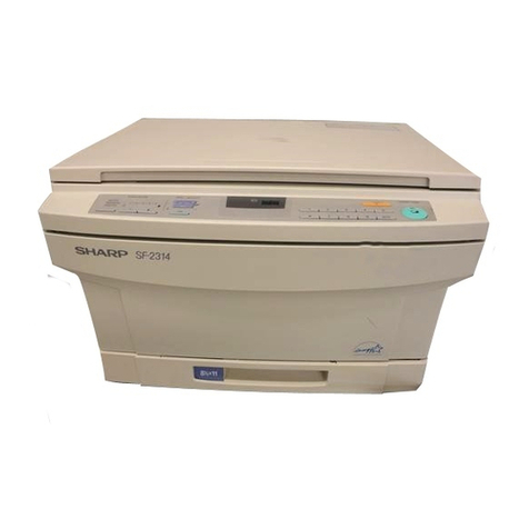
Sharp Z-21 User manual

SERVICE MANUAL
CODE: 00ZZ26SM1E///
MODEL
MODEL Z-21
MODEL Z-26
[ 1 ] BASIC SPECIFICATIONS . . . . . . . . . . . . . . . . . . . . . . . . . . . . . . . . . . . . . . . . . . . .1
[ 2 ] EXTERNAL VIEW AND OPERATION PANEL FUNCTIONAL DESCRIPTIONS . .2
[ 3 ] UNPACKING AND . . . . . . . . . . . . . . . . . . . . . . . . . . . . . . . . . . . . . . . . . . . . . . . . . .5
[ 4 ] SUPPLIES . . . . . . . . . . . . . . . . . . . . . . . . . . . . . . . . . . . . . . . . . . . . . . . . . . . . . . . . .6
[ 5 ] INTERNAL STRUCTURE . . . . . . . . . . . . . . . . . . . . . . . . . . . . . . . . . . . . . . . . . . . . .7
[ 6 ] COPY PROCESS . . . . . . . . . . . . . . . . . . . . . . . . . . . . . . . . . . . . . . . . . . . . . . . . . . .9
[ 7 ] OPERATIONAL DESCRIPTIONS . . . . . . . . . . . . . . . . . . . . . . . . . . . . . . . . . . . . .12
[ 8 ] DISASSEMBLY, ASSEMBLY . . . . . . . . . . . . . . . . . . . . . . . . . . . . . . . . . . . . . . . . .16
[ 9 ] SIMULATION AND SELF DIAGNOSICS . . . . . . . . . . . . . . . . . . . . . . . . . . . . . . . .22
[10] ADJUSTMENTS . . . . . . . . . . . . . . . . . . . . . . . . . . . . . . . . . . . . . . . . . . . . . . . . . . .27
[11] DRUM CARTRIDGE REPLACEMENT . . . . . . . . . . . . . . . . . . . . . . . . . . . . . . . . . .30
[12] CIRCUIT DIAGRAM . . . . . . . . . . . . . . . . . . . . . . . . . . . . . . . . . . . . . . . . . . . . . . . .32
CONTENTS
SHARP CORPORATION This document has been published to be used for
after sales service only.
The contents are subject to change without notice.
Parts marked with "!" is important for maintaining the safety of the set. Be sure to replace these parts with specified
ones for maintaining the safety and performance of the set.

CONTENTS
[ 1 ] BASIC SPECIFICATIONS . . . . . . . . . . . . . . . . . . . . . . . . 1
[ 2 ] EXTERNAL VIEW AND OPERATION PANEL
FUNCTIONAL DESCRIPTIONS . . . . . . 2
1. Operation panel . . . . . . . . . . . . . . . . . . . . . . . . . . . . . . . 2
2. Display descriptions . . . . . . . . . . . . . . . . . . . . . . . . . . . . 3
[ 3 ] INSTALLATION AND STORAGE . . . . . . . . . . . . . . . . . 5
1. Unpacking . . . . . . . . . . . . . . . . . . . . . . . . . . . . . . . . . . . 5
2. A word on copier installation . . . . . . . . . . . . . . . . . . . . . . 5
3. Set-up . . . . . . . . . . . . . . . . . . . . . . . . . . . . . . . . . . . . . . . 5
[ 4 ] SUPPLIES . . . . . . . . . . . . . . . . . . . . . . . . . . . . . . . . . . . . . . 6
1. Drum cartridge, TD cartridge . . . . . . . . . . . . . . . . . . . . . 6
2. How to identify the production control
number . . . . . . . . . . . . . . . . . . . . . . . . . . . . . . . . . . . . . . 7
[ 5 ] INTERNAL STRUCTURE . . . . . . . . . . . . . . . . . . . . . . . . 7
1. PWB arrangement . . . . . . . . . . . . . . . . . . . . . . . . . . . . . 7
2. Motors, solenoids, switches . . . . . . . . . . . . . . . . . . . . . . 8
3. Sensors, thermistor, thermostat . . . . . . . . . . . . . . . . . . . 8
[ 6 ] COPY PROCESS . . . . . . . . . . . . . . . . . . . . . . . . . . . . . . . 9
1. Copy process diagram . . . . . . . . . . . . . . . . . . . . . . . . . . 9
2. Image forming process . . . . . . . . . . . . . . . . . . . . . . . . . . 9
3. Detailed description of image forming process . . . . . . . . 9
[ 7 ] OPERATIONAL DESCRIPTIONS . . . . . . . . . . . . . . . . 12
1. Optical system . . . . . . . . . . . . . . . . . . . . . . . . . . . . . . . 12
1-1. Optical system outline . . . . . . . . . . . . . . . . . . . . . 12
1-2. Void area and image loss . . . . . . . . . . . . . . . . . . . 12
2. Paper feed section . . . . . . . . . . . . . . . . . . . . . . . . . . . . 12
2-1. Paper feed section outline . . . . . . . . . . . . . . . . . . 12
2-2. Outline of paper feed operation . . . . . . . . . . . . . . 13
3. Drive section . . . . . . . . . . . . . . . . . . . . . . . . . . . . . . . . . 13
4. Document table drive section . . . . . . . . . . . . . . . . . . . . 13
4-1. Outline . . . . . . . . . . . . . . . . . . . . . . . . . . . . . . . . . 13
4-2. Outline of operation . . . . . . . . . . . . . . . . . . . . . . . 14
5. Others . . . . . . . . . . . . . . . . . . . . . . . . . . . . . . . . . . . . . . 14
5-1. Fusing temperature control . . . . . . . . . . . . . . . . . 14
5-2. Toner empty control . . . . . . . . . . . . . . . . . . . . . . . 15
[ 8 ] DISASSEMBLY AND ASSEMBLY . . . . . . . . . . . . . . . 16
1. Document cover disassembly . . . . . . . . . . . . . . . . . . . . 16
2. Document table disassembly . . . . . . . . . . . . . . . . . . . . 16
3. Top cabinet disassembly . . . . . . . . . . . . . . . . . . . . . . . 16
4. Operation panel disassembly . . . . . . . . . . . . . . . . . . . . 17
5. Copy lamp PWB disassembly . . . . . . . . . . . . . . . . . . . 17
6. AE sensor removal . . . . . . . . . . . . . . . . . . . . . . . . . . . . 17
7. Main PWB disassembly . . . . . . . . . . . . . . . . . . . . . . . . 17
8. Drive unit disassembly . . . . . . . . . . . . . . . . . . . . . . . . . 18
9. Drive motor disassembly . . . . . . . . . . . . . . . . . . . . . . . 20
10. Power PWB disassembly . . . . . . . . . . . . . . . . . . . . . . . 20
11. Lower heat roller disassembly . . . . . . . . . . . . . . . . . . . 20
12. Heater lamp disassembly . . . . . . . . . . . . . . . . . . . . . . . 20
13. Fusing separation pawl disassembly . . . . . . . . . . . . . . 21
14. Upper heat roller disassembly . . . . . . . . . . . . . . . . . . . 21
15. Paper feed unit and resist roller removal (Z-26) . . . . . . . 21
[ 9 ] SIMULATION AND SELF DIAGNOSTICS . . . . . . . . . 22
1. Simulation . . . . . . . . . . . . . . . . . . . . . . . . . . . . . . . . . . 22
2. Self diag functions . . . . . . . . . . . . . . . . . . . . . . . . . . . . 26
[10] ADJUSTMENTS . . . . . . . . . . . . . . . . . . . . . . . . . . . . . . . 27
1. Lead edge adjustment . . . . . . . . . . . . . . . . . . . . . . . . . 27
2. Exposure adjustment . . . . . . . . . . . . . . . . . . . . . . . . . . 28
[11] Drum cartridge replacement . . . . . . . . . . . . . . . . . . . 30
1. Drum cartridge replacement timing . . . . . . . . . . . . . . . 30
2. Drum cartridge replacement procedure . . . . . . . . . . . . 30
2-1. Drum cartridge replacement . . . . . . . . . . . . . . . . 30
2-2. Counter clear . . . . . . . . . . . . . . . . . . . . . . . . . . . . 31
[12] CIRCUIT DIAGRAM . . . . . . . . . . . . . . . . . . . . . . . . . . . . 32
1. BLOCK DIAGRAM . . . . . . . . . . . . . . . . . . . . . . . . . . . . 32
2. MAIN P.W.B CPU (IC203) SIGNAL NAME . . . . . . . . . 33
3. AC POWER SUPPLY CIRCUIT: 100V SERIES . . . . . 34
4. AC POWER SUPPLY CIRCUIT: 200V SERIES . . . . . 35
5. POWER SUPPLY P.W.B. CIRCUIT – 1/2
(Common section) . . . . . . . . . . . . . . . . . . . . . . . . . . . . 36
6. POWER SUPPLY P.W.B. CIRCUIT – 2/2
(For power unit CPWBF1018FC51 only) . . . . . . . . . . . 37
BIAS CIRCUIT/P.W.B. . . . . . . . . . . . . . . . . . . . . . . . . . 38
7. POWER SUPPLY CIRCUIT – 2/2
(For power unit CPWBF1018FC55, 56 only) . . . . . . . . 39
8. POWER SUPPLY P.W.B.: 100V SERIES . . . . . . . . . . 40
9. POWER SUPPLY P.W.B.: 100V SERIES
(EX. 2PIN PLUG): For power unit
CPWBF1042FC** only . . . . . . . . . . . . . . . . . . . . . . . . 40
10. POWER SUPPLY P.W.B.: 200V SERIES
(EX. 3PIN PLUG): For power unit
CPWBF1043FC** only . . . . . . . . . . . . . . . . . . . . . . . . 41
11. POWER SUPPLY P.W.B.: 200V SERIES
(EX. 2PIN PLUG): For power unit
CPWBF1044FC** only . . . . . . . . . . . . . . . . . . . . . . . . 41
12. MAIN CONTROL CIRCUIT – 1/3
(CPU CONTROL SECTION) . . . . . . . . . . . . . . . . . . . . 42
13. MAIN CONTROL CIRCUIT – 2/3
(I/O, COPY LAMP CONTROL SECTION) . . . . . . . . . . 43
14. MAIN CONTROL CIRCUIT – 3/3
(High voltage power section) . . . . . . . . . . . . . . . . . . . . 44
15. MAIN CONTROL P.W.B. . . . . . . . . . . . . . . . . . . . . . . . 45
16. OPERATION CIRCUIT/P.W.B.-1: FOR Z-21 . . . . . . . . 46
17. OPERATION CIRCUIT/P.W.B.-2: FOR Z-26 . . . . . . . . 47
18. COPY LAMP CIRCUIT/P.W.B.-1: 100V SERIES . . . . . 48
19. COPY LAMP CIRCUIT/P.W.B.-2: 200V SERIES . . . . . 48
20. MES (Motor Encorder Sensor) CIRCUIT/P.W.B. . . . . . 48
21. TIMING CHART . . . . . . . . . . . . . . . . . . . . . . . . . . . . . . 49
22. ACTUAL WIRING CHART-1: FOR Z-21 . . . . . . . . . . . 51
23. ACTUAL WIRING CHART-2: FOR Z-26 . . . . . . . . . . . 52
[1] BASIC SPECIFICATIONS
Type: Portable
Copy system: Dry, plain paper copier
Document kind: Sheet, book. Max. weight 2 Kg. (2.2lbs)
Document size: Max. A4 (210±1 x 2971±1mm) Letter (8-1/2" x
11", 8-1/2" ±5/128" x 11" ±5/128")
Copy size: A4 A6, 8-1/2" x 11" to 4" x 6"
Copy speed: Z-26: 3 sheets/min
Z-21: manual single paper feed only
Fast copy: 1About 19 sec (Except in the auto start mode
and the auto power shut off
mode, rated voltage, 20 C,
65%RH)
2About 24 sec (In the auto start mode and the
auto power shut of mode,
rated voltage, 20 C, 65%RH)
Warm-up time: None
Multicopying (Z-26 only):
1 to 9 sheets, continuos copy mode (20 sheets),
and auto repeat function available.
Copy magnification ratio:
1:1±1%
Exposure system: Slit exposure by the moving document table
Paper feed system: Z-26, Multi paper feed and single paper feed
by manual paper feed tray;
Z-21, Manual single paper feed only
Paper feed capacity (multi paper feed):
Overall stack thickness 5.0mm max.
About 50 sheets (75g/m2(20 lb) paper), about 40
sheets (80g/m2(21 lb) paper)
Developing system: Dry type two-component magnetic brush
developing
Fusing system: Heat roller
Light source: Tungsten lamp
Power source: Voltage for each destination ±10%, 15A
(50/60Hz common)
Power consumption:
Max. 690W (10WH or less in auto power shut off)
External dimensions:
Z-26, 378(W) x 353(D) x 98(H)mm;
Z-21, 362(W) x 353(D) x 98(H)mm;
Installation space: Z-26, 725(W) x 353(D)mm;
Z-21, 675(W) x 353(D)mm
Weight: Z-26: 6.7kg (14.9 lb)(Including 0.7kg
developer cartridge)
Z-21: 6.6kg (including 0.7kg developer
cartridge.)
Working environment:
Temperature 10 to 30°C
Humidity 20 to 85%
Accessories: Developer cartridge (black) x 1 pc. (Optionally
available for U.S.A., Canada, and Singapore.)
Photoconductor cartridge x 1 pc.
Power cord
Operation manual
Guarantee paper(Australia, New Zealand,
Canada only)
MSDS sheet (U.S.A., Canada, U.K. only)
Service label (U.S.A. only)
On-site warranty registration sheet (U.K. only)
Dust cover (Only in some areas)
Options: Developer cartridge (black, red, blue)
Photoconductor cartridge
– 1 –

[2] EXTERNAL VIEW AND OPERATION PANEL FUNCTIONAL DESCRIPTIONS
1. Operation panel
The illustrations show the Z-26.
Document cover
Document glass
Operation panel
(Refer to the "2. Display descriptions.")
Exit tray
(Z-26 only)
Front cover
(Available in three colors: black, red,
and blue. For the parts codes and
standard life, refer to [4] SUPPLIES.)
TD cartridge
Rear side
Power switch
Paper tray
(Z-26 only)
Paper guide
Front-cover open button
Power cord socket
If the document table is moved without
pressing this button, an necessary load
is applied to the drive section, causing a
damage.)
Release button
(When moving the document table manually
be sure to press and hold this button while
moving.
Handle
Fusing area
Do not touch directly with hands. Oil on the
hand attaches to the drum and causes poor
copy quality.
Photoconductive drum
Be careful not to scratch. Scratches on the
drum may effect copy quality. Deep
scratches may generate bias defects to
disable the use of the photoconductor
cartridge.
Since the photoconductor drum responds to
lights, do not expose the drum to light for long
periods of time.
Drum cartridge release lever
Bottom cover release lever
Bottom cover
– 2 –

2. Display descriptions
Z-26 Z-21
C
PRINT key
READY indicator
C (clear) key
COPY QUANTITY key
EXPOSURE key
EXPOSURE indicators
Misfeed indicator
TD cartridge replacement indicator
Tone seve indicator
TS
A
COPY QUANTITY display
Misfeed indicator
TD cartridge replacement indicator
Exposure indicators
READY indicators
EXPOSURE key
Tone seve indicator
TS
A
Name Functions
READY indicator Z-21: This indicator shows three states: ready, auto start, and auto power shut off mode.
Ready state: When the power is turned on, this indicator lights up to show the machine is ready for copy
operation, and for key input reception.
Auto start: When a paper is inserted into the paper feed port, the READY indicator goes off. In about 5
sec, copying is automatically started.This occurs for the first copy after turning on main switch.
Auto power shut off mode: After turning on the power or after completion of copying, if no copy paper is
inserted for about 90sec, power supply to the heat roller is turned off. At this time, the READY indicator
slowly blinks. The auto power shut off mode is cancelled by pressing any key or inserting of a copy
paper.
Z-26: This indicator shows three states: ready, copying, and auto power shut of mode.
Ready state: Same as the Z-21.
Copying: When the PRINT key is pressed with paper set on the paper feed tray, the READY indicator
turns off and copying is started in about 5 sec.
Auto power shut off mode: In the Auto Power Shut OFF mode, copy will be started in the copy condition
set on the display when you press a copy key which can be canceled by entering any key.
CLEAR key (Z-26 only) •Performs cancelation of the multi copy set quantity and the auto repeat function, and suspends copying
before and during copying.
When the key is pressed during multi copying, copying is terminated and the copy quantity display shows
"0".
•When the clear key is pressed for 5 sec, the content of the total counter is displayed, starting with the digit of
ten thousands one by one on the copy quantity display.
COPY QUANTITY key
(Z-26 only) •This key allows setting of copy quantity from 1 to 9 and of C mode (20-sheet continuous copying).
•When this key is kept down, the copy quantity display counts up. After the count reaches 9, "C" is displayed
next.
•The display counts down during continuous copying to show the rest of the copies to be made.
When, however, the "C mode" is set, count down is not performed. In this case, press the COPY QUANTITY
key during copying to display the copied number. (The copied number is displayed only when it is 9 or less.
If it is 10 or more, "C" is displayed.)
COPY QUANTITY display
(Z-26 only) •Displays the set copy quantity, the self diag code, and the simulation number.
•The set copy quantity is automatically cleared to "0" if no key input and no copy operation is made for 60 sec
after completion of copying.
– 3 –

Name Functions
EXPOSURE key •This key allows setting of auto exposure (one step) and manual exposure (three steps: Light, Normal, and
Dark), and the toner save mode.
•Display cycle of each exposure mode.
•Change in exposure setting is valid after turning on the COPY key and the PRINT key (after insertion of a
copy paper in the case of Z-21) until the table enters scanning operation.
•When the toner save mode is selected, the toner concentration is made smaller than in the standard mode,
saving the toner consumption by from manual (standard) about 20%.
•The copy lamp light quantity can be adjusted to cope with deterioration of the photoconductor or dirt in the
optical system (User simulation).
<<Procedure>>
1Press and hold the EXPOSURE key for 10 sec in the ready state or in the auto power shut off mode.
2The currently selected LED of the three LEDs of copy exposure blinks, and the READY indicator turns off.
(At initializing, "A" blinks.)
3Set a desired exposure with the EXPOSURE key, and wait for 5 sec.
4The machine goes into the ready state.
5When the power is turned off/on during simulation, exposure is set to the level just before turning off the
power. The CLEAR key input is not accepted during simulation.
•If there is no key input and no copy operation, the set copy exposure is automatically cleared and the display
returns to "A".
EXPOSUREindicator •Displays the value set by the EXPOSURE key.
•In the case of Z-21, it is used also for counter read and when trouble occurs.
Toner save mode display lamp •Displays the toner save mode selected by the copy density key.
TD cartridge replacement
indicator •When toner empty is detected at the begining of a copy run, the TD cartridge replacement indicator lights up
and the machine enters toner supply operation for max. 60 sec. (The document table reciprocates max. 3
times.) If toner supply is completed, the indicator turns off. If toner empty is detected again, the indicator
blinks to stop the machine. After this state, when the power is turned off/on and a copy paper is inserted,
toner supply (max. 60 sec) operation is repeated. After completion of the operation, when toner empty is
detected, the machine is stopped. The user must replace the TD cartridge with a new one.
•When toner empty is detected during copying, toner supply is performed (without display) when the table
returns.
Misfeed indicator •When a misfeed occurs inside the machine, the misfeed indicator blinks. Open the bottom cover, remove the
jam paper, close the bottom cover, and set the machine horizontally. Then turn off/on the power, and the
indicator will turn off. If a jam paper is detected inside the machine, the indicator blinks again.
When the main body is put aside with the power ON, the indicator blinks. This can be cancelled by turning
off/on the power in the horizontal position.
Exposure cycle
1. Auto
Light
Auto DarkToner save
Display
Light
Auto DarkToner save
Light
Auto DarkToner save
Light
Auto DarkToner save
Light
Auto DarkToner save
Light
Auto DarkToner save
3. Manual (Light)
2. Manual (Normal)
4. Manual (Dark)
5. Toner save mode
6. Auto
∗
Repated
– 4 –

[3] INSTALLATION AND STORAGE
1. Unpacking
@Save the carton and packing materials. The carton and packing
can be re-used for transporting the machine, should it be neces-
sary.
2. A word on copier installation
Improper installation may damage the copier. Please note the follow-
ing during initial installation and whenever the copier is moved.
1. Be sure to use a correctly rated power supply and to ground the
copier.
2. Do not plug the copier into an outlet used by other appliances.
3. Do not install your copier in areas that are:
•damp, humid, or very dusty;
•exposed to direct sunlight;
•poorly ventilated;
•subject to extreme temperature or humidity changes, e.g., near
an air conditioner or heater.
4. Although the copier can be stored standing up, place the copier
on a firm, level surface when using it.
A small amount of ozone is produced within the copier during opera-
tion.
The emission level is insufficient to cause any health hazard.
NOTE:
The present recommended long term exposure limit for ozone is 0.1
ppm (0.2 mg/m3) calculated as an 8 hr. time-weighted average con-
centration.
However, since the small amount that is emitted may have an objec-
tionable odor, it is advisable to place the copier in a ventilated area.
CAUTIONS:
1. Do not expose the photoconductive drum to direct sunlight, and
do not touch the photoconductive drum. Scratches or smudges on
the drum will cause dirty copies.
2. The fusing area is hot. Exercise care when inspecting this area.
3. If the copier is moved from a cool place to a warm place, conden-
sation may form inside the copier. Operation in this condition will
cause poor copy quality and malfunctions. Leave the copier at
room temperature for at least 2 hours before use.
3. Set-up
1. Remove the copier from the bag and remove the two wing screws
from the bottom side of the copier.
•Also remove the two pieces of tape securing the bottom cover.
2. Remove all pieces of tape from the copier.
Power cord
Operation manual
TD(Toner/Developer)
cartridge
Paper tray
Carton
Copier
Tape
Tape
– 5 –

3. Press the front-cover open button to unlatch the front cover and
open it.
4. Remove the TD (Toner/Developer) cartridge from the bag.
5. Shake the TD cartridge horizontally four or five times.
6. Remove the cover from the TD cartridge.
•Save the TD cartridge cover. This should be used to pack the
TD cartridge if the copier must be shipped for servicing or in
case you move.
7. Slide the TD cartridge in until it locks in place.
8. Close the front cover.
9. Fit the paper tray in the copier by inserting it at an upward angle
into the grooves on the sides of the paper feed slot. (Z-26 only)
10. Unfold and open the exit tray. (Z-26 only)
11. Plug the power cord into the copier and then plug the other end
into the nearest outlet.
NOTE:
Be sure to insert the power cord firmly.
12. Turn the power switch on.
•When making a copy for the first time after the set-up, the
document glass will slide back and forth and the indicator
will light for up to one minute. Then, copying will start.
Front-cover open button
h
[4] SUPPLIES
1. Drum cartridge, TD cartridge
Item Contents Life Approx. Mode Number Storage conditions
Drum cartridge Drum cartridge x 1
Drum Replacement
Procedure Manual x 1
10,000 copies ZT-20DR
Toner/Developer
Cartridge Toner/Developer Cartridge (Black) @2,000 copies ZT-20TD1
Toner/Developer Cartridge (Red) @1,500 copies ZT-20TD2
Toner/Developer Cartridge (Blue) @1,500 copies ZT-20TD3
@A4 or letter, white-black ratio of 5%
90%
20%
-5˚C
40˚C
Temperature
Humidity
Storage conditions
– 6 –

2. How to identify the production control
number
<<TD cartridge>>
The control number label is on the top of the TD cartridge, which
shows the year and the month of the production.
Destination No.
Japan Black option 1
Outside Japan Black option 2
Japan Red option 3
Outside Japan Red option 4
Japan Blue option 5
Outside Japan blue option 6
Japan Same package 8
Outside Japan Same package 9
<Drum cartridge>
The control number label is on the top of the drum cartridge, which
shows the year and the month of the production.
The last
digit of
the year
Serial No.
(00001 ∼99999)
Destination
(1~9) The month
of the
production
Jan.
Sep.
Oct.
Nov.
Dec.
. . . 1
. . . 9
. . . 0
. . . X
. . . Y
.
.
..
.
.
31000819
The last
digit of
the year
Serial No.
(00001 ∼99999)
Factory
(Normally "5") The month
of the
production
Jan.
Sep.
Oct.
Nov.
Dec.
. . . 1
. . . 9
. . . 0
. . . X
. . . Y
.
.
..
.
.
35000019
Display position
<Display example>
[5] INTERNAL STRUCTURE
1. PWB arrangement
Name Functions
1Main PWB
In addition to overall function control,
this PWB also functions as the copy
lamp control circuit and the high
voltage output circuit (except for
developing bias). The paper exit
sensor in on this PWB also.
2Power PWB
This PWB supplies power to each load.
It is equipped with the power switch,
the power inlet, the interlock switch,
document table sensor, and the paper
entry sensor and the circuit which
generates developing bias.
3Operation PWB Differs in the Z-21 and in the Z-26.
4Copy lamp PWB Different from the conventional models,
the PWB is equipped with a fuse bulb.
5Motor control
PWB
Pulses to control the drive motor and
the paper start (PS clutch ON timing)
are generated by the encoder attached
to the drive motor shaft, and are
converted into electrical signals.
1
2
4
5
3
– 7 –

2. Motors, solenoids, switches
Name Circuit
diagram
code Type Function
1Drive motor MM DC motor Drives all loads.
2Toner
supply
solenoid THS Solenoid Toner supply is
performed when the
solenoid is on.
3PS
solenoid RRS-A
RRS-B Solenoid
When the solenoid is
on, the paper which is
resisted at the paper
gate (Resist roller) is
fed
4Paper feed
solenoid
PFS
(Paper
Feed) SOlenoid
Used only in the Z-26.
When the solenoid is
on, the paper takeup
roller is driven.
5Interlock
switch ——
By opening the bottom
cover or remove the
TD cartridge, the
interlock switch
functions to stop the
power supply.
6Power
switch MSW — —
7Power inlet Inlet — AC cord connecting
terminal
3. Sensors, thermistor, thermostat
Name Circuit
diagram
code Type Function
1Paper feed
sensor PID (Paper
in detector) Photo sensor Senses paper
entry.
2Paper exit
sensor
POD
(Paper out
detector) Photo sensor Senses paper exit.
3Document
table
sensor
TPS
(Table
position
sensor)
Photo sensor Senses the
document table
position.
4AE sensor
AESP
(Auto
exposure
sensor)
Photo sensor Reads the
document density.
5Motor
encoder
sensor
MREP
(Motor
rotary
encoder
port)
Photo sensor Reads the encoder
pulse.
6Thermistor HLTH
(Heat roller
thermistor) Thermistor Senses the fusing
temperature.
7Thermostat — Thermostat
When the fusing
temperature rises
abnormally, the
thermostat opens
to stop power
supply to the
heater lamp.
(165°Ctype
employed.)
1
36527
4
7
2
65
4
3
1
– 8 –

[6] COPY PROCESS
This model uses an OPC. (photoconductor) drum to form an image
on it.
1. Copy process diagram
2. Image forming process
Brief description of image forming process:
A charge is applied on the entire drum surface, onto which the
image of the original is projected by means of the copy lamp
selfoc. Where the light strikes the drum, the charge dissipates and
an electrostatic latent image is formed on the drum surface. Toner
is attracted to the electrostaticly charged areas of the drum to
form a visible image.
Step 1. Photoelectrical discharge (residual charge on the drum sur-
face is neutralized)
Step 2.
Step 3. Change
Exposure(a latent image is formed on the drum surface)
Step 4. Developing (the latent image on the drum is developed into
a visible image with toner)
Step 5. Transfer (the visible image, toner image, on the drum sur-
face is transferred onto the copy paper)
Step 6. The potential on the transfer paper is neutralized, and the
paper is separated.
Step 7. Cleaning (residual toner on the drum surface is collected by
the cleaning blade)
Step 8. Photoelectric discharge (residual charge on the drum sur-
face is neutralized)
3. Detailed description of image forming
process
Step 1. Photoelectric discharge
Prior to charging, light from the copy lamp is projected over the drum
surface to reduce electrical resistance of the OPC layer and neutral-
ize any residual charge.
As the electrical resistance is decreased, the positive charge in the
aluminum layer neutralizes the negative charge in the OPC layer.
Exposure
Main corona
Charge
Discharge
Drum
Cleaning
Cleaning blade
Waste toner collection
Paper exit
Fusing Separation
Heat roller
Heater lamp
Transfer
Developing
Toner
Developer
Sync with
drum
Original
Copy lamp SELFOC lens
Paper stoper
Separator pin Transfer corona
Paper feed
Resist roller
Copy lamp
– 9 –

Step 2. Charge
A uniform negative charge is applied over the OPC drum surface by
the main corona unit. (Controlled by the grid bias.)
Step 3. Exposure (copy lamp and SELFOC lens)
The image of the original is projected onto the OPC drum through the
SELFOC lens by means of the light from the copy lamp. Where light
strikes the drum light areas of the original, the electrical resistance in
the OPC layer decreases and the charge dissipates. This forms the
electrostatic latent image on the drum surface.
Step 4. Developing
Toner is attracted from the MG roller to the latent image on the drum
surface forming a visible image. With this two component magnetic
brush type developing method, the toner is charged positive because
of friction with the carrier and is, therefore, attracted to the deposits
the negatively charged areas (imaged areas) on the drum surface.
In this process, a bias potential is applied to the MG roller (magnet
roller) to prevent the toner from being attracted to the residual poten-
tial (approx. –80 to –100V) in the non-imaged areas after exposure.
Step 5. Transfer
The visible image (toner image) on the drum is transferred onto the
copy paper.
A high potential is applied to the back of the copy paper by negative
corona discharge, making the attraction between the drum and toner
less than the attraction between the copy paper and toner. As a
result, toner adheres to the copy paper.
The resulting transfer efficiency is 70 to 80% therefore 20 to 30% of
the toner remains on the drum after transfer, residual toner.
Screen grid
OPC layer
Pigment layer
Aluminum
layer
OPC layer
Aluminum
layer
SELFOC lens
Exposure
(Copy lamp)
Drum surface charge
after exposure
Dark
Black area
of original
Light
White area
of original
Halftone
Gray area
of original
Pigment layer
MG roller
S
N
S
Carrier
:
:
Toner
(N) (S) Permanent magnet
(3-pole fixed type)
– 10 –

Step 6. Separation
The paper is negatively charged (About –3KV) by the discharge pin to
neutralize the potential, separating the paper from the drum.
Step 7. Cleaning
The residual toner remaining on the drum is collected by the cleaning
blade and carried into the toner collection unit.
Step 7. (same as step 1)
<Transition in the drum surface potential at each step>
Because of the developing bias, toner is not attracted to the non-
image areas of the drum surface. If, for any reason, the developing
bias fails, the toner will be attracted to the residual charge on the
drum producing background in the non-image areas.
Cleaning blabe
Residual toner
Toner
collection
unit
0
Drum surface potential
White image
area
Canceled by
developing bias
Charge Exposure Developing Transfer
Discharge
Charge
Time
-600
Toner attract
potential
Residual potential (-80~100V)
-100
-150
-150V
Black image area
– 11 –

[7] OPERATIONAL DESCRIPTIONS
1. Optical system
1-1. Optical system outline
Light source: Fuse bulbs are used as the light source. Eight fuse
bulbs are arranged in series on the PWB. The
temperature fuse is also installed on the PWB. The
copy lamp also has the function as the discharge
lamp to attenuate the potential on the drum.
Lens: A selfoc lens is employed.
AE sensor: A photo sensor is employed to read document den-
sity for improving maneuverability and stabilizing pic-
ture quality.
1-2. Void area and image loss
1Void area: With the original cover open, make a copy without an
original in place. The white area on the copy is called "void area."
2Image loss: Loss (or area) of the image lost on the copy.
3Specified values of void area and image loss
Void area Lead edge 1 ∼5mm max.
Image loss Lead edge 2mm max.
2. Paper feed section
2-1. paper feed section outline
The paper feed section differs greatly from the models: the Z-21 and
the Z-26.
In the Z-26, max. 50 sheets of paper can be set on the multi tray, and
max. 20 sheets of multi copy run is available.
In the Z-21, only single manual feed is available.
The figure below shows the cross section of the Z-21 and the Z-26.
<Z-26>
<Z-21>
Copy lamp unitCopy lamp
Discharge light
Drum
SELFOC lens
AE sensor
Document
table
(Document)
Copy
Lead edge image loss 2mm max
Resist roller
Paper in detection
switch (PID) Paper feed roller
Stopper
Take-up roller
[Paper feed side]
Friction plate
Paper stopper
Paper in detection switch (PID)
Resist roller
[Paper feed side]
– 12 –

2-2. Outline of paper feed operation
<<Z-26>>
1When the COPY key is pressed, the motor starts rotating. At the
same time, the paper feed solenoid turns on to raise the stopper.
2Paper is fed and the paper entry sensor (PID) is turned on.
3The paper is stopped by the resist roller. After 2.3 sec from driving
the table position signal (TPSP) LOW, the resist roller solenoid
turns on to rotate the resist roller, transporting the paper to the
transfer section.
(Timing chart: Paper feed operation)
<<Z-21>>
1When a paper is inserted into the paper feed port, the paper entry
sensor turns on.
2The motor starts rotating to rotate the resist roller, transporting the
paper to the paper stopper position.
32.8sec after rising of the table position sensor (TPSP), the paper
stopper solenoid turns on to allow the paper to be transported to
the transfer section.
(Timing chart: Paper feed operation)
@RRS-A and RRS-B are signal timings.
The paper stopper turns on at RRS-A timing.
3. Drive section
All drive operations in this model are performed by one motor. The
motor drive is transmitted through the drive unit to each section (the
paper feed section, the developing section, the drum unit, the docu-
ment table, the fusing section, and the fan unit).
4. Document table drive section
4-1. Outline
The document table is driven by a gear unit and the endless rack
which is integrated with the document table. A clutch is not used for
selecting feed and return.
The structures of the endless rack and the C bracket unit (gear unit)
are described in the following.
The endless rack is composed of the feed rack and the return rack as
shown in the figure above. The drive gears are utilized two ways: the
feed gear set and the return gear set. The bracket guide moves
along the groove in the rack cover. These parts provide feed and
return operations while keeping the same gear rotating direction.
1Copy key
1Motor
(M.M)
1Paper feed
solenoid (PFS)
2Paper entry
sensor (PID)
3Resist roller
solenoid
Table position
sensor (TSPS)
About 2.3sec
1
2
1
1
2
3
1
2Motor
(M.M)
3Paper stopper A
(RRS-A)
3
Paper entry
sensor (PID)
Table position
sensor (TSPS)
About 2.8sec
Paper stopper B
(RRS-B)
500ms
1
2
23
Toner hopper
drive gear
Developing tank magnet roller drive gear
Document table drive gear
Motor gear
Upper heater
roller gear
Heater roller drive gearDrum and transport
section drive gear
PS roller drive gear
C bracket unit Feed rack (Small pitch)
Return rack
(Large pitch)
Return gear
Feed gear
Bracket guide
Endless rack
Document cover
Feed rack
Bracket guide
Return gear
Return rack
Feed gear
– 13 –

4-2. Outline of operation
Positions of the racks, the bracket guide, and the C bracket are
shown below:
5. Others
5-1. Fusing temperature control
1When the power is turned on, the power relay is also turned on at
the same time. After 300ms, the heater lamp turns on (ready
state).
2During copying, the fusing temperature is controlled to about
149°C.
3After turning on the power or after completion of copying, if there
is no key input for 90 sec, the power supply to the heater lamp is
stopped. (Auto shut off function)
4In the auto shut off mode, if any key input is made or a paper is
inserted (in the case of Z-21), the power relay is turned on to turn
on the heater lamp (ready state).
When the heater lamp temperature rises above 180°C, a high
temperature trouble is displayed ("H3" lamp lights up (Z-26); all lamps
except for READY lamp light up (Z-21)), and power supply to the
heater is stopped.
Bracket guide
Rack guide
[When ready]
Bracket guide
[Move to the document scan start position]
Bracket guide position
Bracket guide
Bracket guide
[Document scan (feed) start]
Bracket guide
[Document scan (feed) end]
Bracket guide
Bracket guide
[Move to stop position]
1 2 3 4
Power switch
Power realy
Heater lamp
300ms
2.3sec
300ms
– 14 –

5-2. Toner empty control
1When the paper entry sensor (Z-21) or the COPY key (Z-26) is
turned on, if the toner control sensor output (TCS) is HIGH, the
toner supply solenoid (THS) is turned on to supply toner.
2If TCS is not driven LOW after 60 sec of toner supply, the
developer cartridge replacement lamp is lighted and the machine
is stopped.
3In the case of the Z-26, if the toner control sensor signal keeps
HIGH during 12 sheets of multi copying, the developer cartridge
replacement lamp is lighted and the machine is stopped.
10sec
300msec 2.4sec
1.0sec
1.0sec
200msec
5.0sec
54sec
200msec
1.9sec
x 582 pulese
250msec
500msec
Paper in sw
Copy key
TCS
(Toner control sensor)
THS
(Toner supply solenoid)
Bias
(DV-Bias)
Motor
Copy lamp
H.V.
(High voltage)
Grid
Table position
TEL
(TD cartridge indicator)
Home position
Toner enpty
– 15 –

[8] DISASSEMBLY AND ASSEMBLY
<<Note for disassembly and assembly>>
(1) When disassembling, disconnect the power plug. Never remove
or assemble the PWB or connectors with the power ON.
(2) Be careful not to drop small parts and screws inside the
machine. It may cause damage.
(3) Do not pull on wires of the connector, or wires may be damaged.
Be sure to hold the both sides of the connector when pulling.
(4) Descriptions on the cable holder and harness band are omitted
unless special note is required. When these parts must be
separated in disassembly, be sure to note the attaching posi-
tions of them.
(5) Use care in wire treatment. Do not allow pinches of lead wires.
(6) Do not tighten the screws too much. Avoid breaking the screw
threads.
1. Document cover disassembly
•Warp the center portion of the document cover and lift it upwards.
2. Document table disassembly
1Remove four screws which are fixing the rack cover, and remove
the rack cover.
2Remove the rack gear bracket.
@Note position of each component for reassembly.
3Slide the document table, and remove three screws which are
fixing the sliding rail to the top of the machine.
4Slide the table backwards to remove.
3. Top cabinet disassembly
1Remove the document table.
2Open the front door, and remove the TD cartridge.
3Remove the five screws which are fixing the top cabinet.
4Remove the top cabinet upwards.
Document cover
Secure here
Secure here
Rack cover
Top cabinet
TD cartridge
– 16 –

4. Operation panel disassembly
1Remove the document table.
2Remove the top cabinet.
3Remove the screw which is fixing the operation panel, and
remove the connector.
5. Copy lamp PWB disassembly
1Remove the document table.
2Remove the top cabinet.
3Remove the reflector. (Be careful not to touch the reflection sec-
tion of the reflector.)
4Remove the copy lamp PWB. (Do not touch the fuse bulb of the
lamp directly with your hand. It may result in a shortened life and
uneven exposure.)
6. AE sensor removal
1Remove the document table.
2Remove the top cabinet.
3Remove the copy lamp unit (four screws).
4Remove the screw which is fixing the AE sensor, and remove the
AE sensor.
7. Main PWB removal
1Remove the document table.
2Remove the top cabinet.
3Remove the fan unit. (2 screws)
@During reassembly,ensure fan belt tension is correct.
Operation panel PWB
Reflector
Copy lamp PWB
Copy lamp unit
AE sensor
Copy lamp unit
Fan unit
– 17 –

4Remove the MC cable (red) and GRID cable (white). (1 screw for
each)
@Note for attachment:
1Be careful not to mistake the attachment position of each
cable. (Refer to the figure above.)
2The spring terminal must be on the cable terminal.
5Disconnect the connector, and remove four screws and the
main PWB.
8. Drive unit disassembly
1Remove the document table.
2Remove the top cabinet.
3Remove the bottom cabinet.
4Remove the drum cartridge.
Spring
White
Red
Main PWB
Bottom cabinet
– 18 –
This manual suits for next models
1
Table of contents
Other Sharp Copier manuals

Sharp
Sharp AR-122E User manual

Sharp
Sharp AL-1550 User manual

Sharp
Sharp AR-M207 User manual

Sharp
Sharp AR-160 User manual

Sharp
Sharp AR-C330 Key operators User manual

Sharp
Sharp AR-M201 Setup guide

Sharp
Sharp DM-FX1 User manual

Sharp
Sharp Z-25 User manual

Sharp
Sharp AL-1041 - B/W Laser Printer User manual

Sharp
Sharp AR-5015 N User manual