Sharp AL-1020 User manual

SERVICE MANUAL
CODE: 00ZAL1250/A1E
DIGITAL COPIER
AL-1020
AL-1200
AL-1220
MODEL AL-1250
* This Service Manual describes only the differences from
the AL-1000/1010. For the common items with the
AL-1000/1010,please refer to the AL-1000/1010 manual.
CONTENTS
SHARP CORPORATION This document has been published to be used for
after sales service only.
The contents are subject to change without notice.
Parts marked with " " is important for maintaining the safety of the set. Be sure to replace these parts with specified
ones for maintaining the safty and performance of the set.
[ 1 ] GENERAL. . . . . . . . . . . . . . . . . . . . . . . . . . . . . . . . . . . . . . . . . . . . . 1 - 1
[ 2 ] SPECIFICATIONS . . . . . . . . . . . . . . . . . . . . . . . . . . . . . . . . . . . . . . 2 - 1
[ 3 ] EXTERNAL VIEWS AND INTERNAL STRUCTURE. . . . . . . . . . . . 3 - 1
[ 4 ] UNPACKING AND INSTALLATION . . . . . . . . . . . . . . . . . . . . . . . . 4 - 1
[ 5 ] OPERATIONAL DESCRIPTIONS . . . . . . . . . . . . . . . . . . . . . . . . . . 5 - 1
[ 6 ] DISASSEMBLY AND ASSEMBLY. . . . . . . . . . . . . . . . . . . . . . . . . . 5 - 2
[ 7 ] SIMULATION,TROUBLE CODES . . . . . . . . . . . . . . . . . . . . . . . . . . 7 - 1
[ 8 ] USER PROGRAMS . . . . . . . . . . . . . . . . . . . . . . . . . . . . . . . . . . . . . 8 - 1
[ 9 ] ELECTRICAL SECTION . . . . . . . . . . . . . . . . . . . . . . . . . . . . . . . . . 9 - 1
[10] CIRCUIT DIAGRAM . . . . . . . . . . . . . . . . . . . . . . . . . . . . . . . . . . . 10 - 1
●PARTS GUIDE
AL-1250

[1] GENERAL
1. General
This model is a digital personal copier produced with key words
of “Comfort able copy, Clear copy, Easy copy” providing high
copy performances and copy productivity.
2. Target User Copy Volume: Monthly Average
Copies: 400 ∼800 (Max. 800)
Prints: 400 ∼800 (Max. 800)
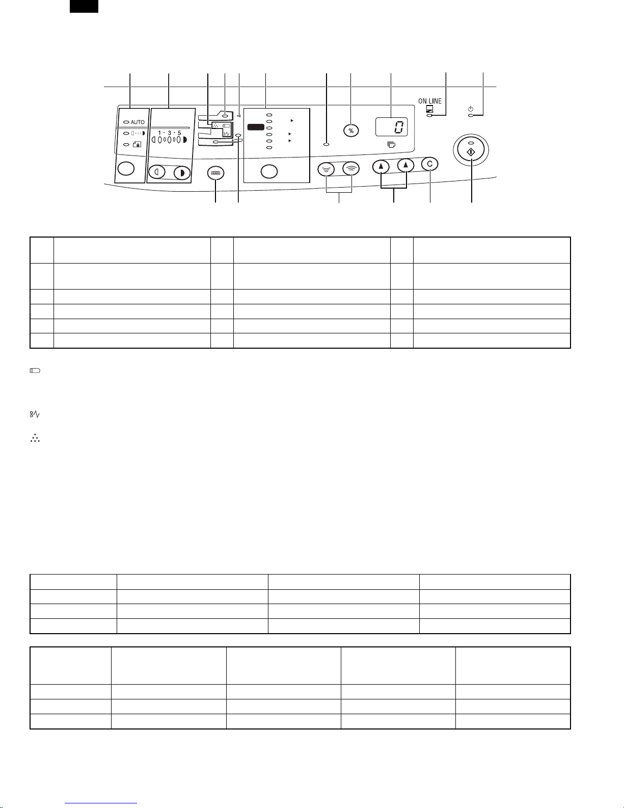
3. Main features
A. High-speed laser copying
●Since warm-up time is zero, copying can be started imme-
diately after the power switch is turned on.
●First-copy time is only 9.6 seconds (normal mode).
●Copying speed is 10 copies/min. (AL-1020) or 12
copies/min. (AL-1220/AL-1250), which adapts to business
use, allowing improvement of working efficiency.
B. High-quality digital image
●High-quality image copying at 600 dpi can be performed.
●In addition to the automatic exposure mode, the manual ex-
posure can be adjusted in five steps.
●The photo mode copying function allows clear copying of
delicate halftone original images such as monochrome
photos and color photos.
C. Substantial copying functions
●Zoom copying from 50% to 200% in 1% increments can be
performed.
●Continuous copying of maximum 99 sheets can also be per-
formed.
●Automatic document feeding through the single pass feeder
(SPF) can be performed.
●Toner save mode reduces toner consumption by ap-
proximately 10%.
●User programs allow setting/modification of functions for
customer’s needs.
D. Scan once/Print many
This copier is equipped with a 1-page memory buffer. This
Memory allows the copier to scan an original 1 time only and
make up to 99 copies. This feature allows for improved
workflow, reduced operating noise from the copier and reduced
wear and tear on the scanning mechanism. This feature
provides for a higher reliability.
E. Printer feature
The AL-1250 copier can be used as a laser printer. The AL-
1020 and AL-1220 copiers can be used as a laser printer by in-
stalling an optional printer upgrade kit.
F. Environmentally friendly design
Paper output tray is housed in the copier for space saving.
Preheat mode and auto power shut-off mode are provided to
reduce power consumption in standby mode.
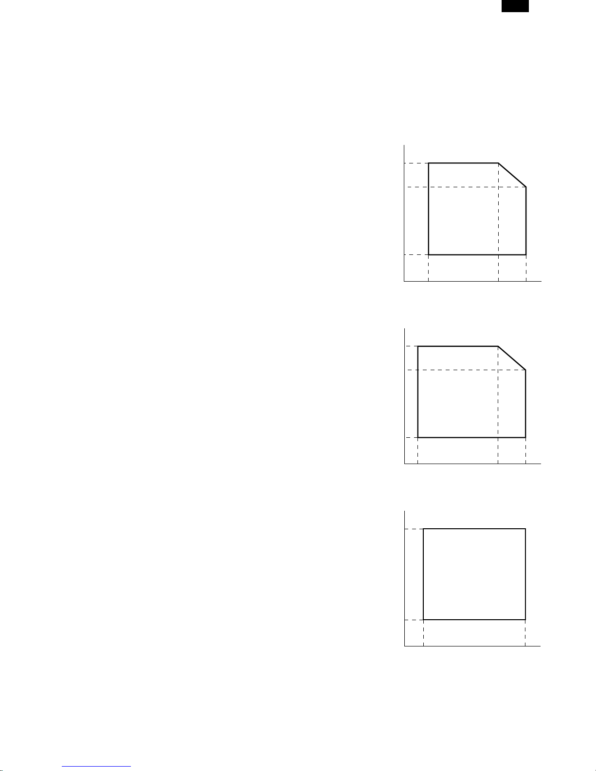
4. Environmental
The environmental conditions for assuring the copy quality and
the machine operations are as follows:
A. Normal operating condition
Temperature:20˚C~25
Humidity:65 ±5%RH
B. Acceptable operating condition
C. Optical condition
D. Supply storage condition
Humidity (RH)
85%
60%
20%
10˚C 30˚C 35˚C
Humidity (RH)
90%
60%
15%
–25˚C 30˚C 40˚C
Humidity (RH)
90%
20%
–5˚C 45˚C
AL-1250
1-1

[2] SPECIFICATIONS
1. Basic specification
Item AL-1020 AL-1220 AL-1250 AL-1200
External dimensions (W ×D ×H) (mm) H379 ×W518 ×
D477 mm ←H464 ×W518 ×
D477 mm H293 ×W518 ×
D445 mm
Weight 21.5 kg 21.5 kg 24.5 kg 18.0 kg
2. Operation Specification
Section item Details AL-1020 AL-1220 AL-1250 AL-1200
Paper feed
section Paper feed
system
1 tray (250
sheet) + Multi
bypass (50
sheet)
←
2 tray (250
sheet ×2) +
Multi bypass
(50 sheet)
1 tray (250
sheet) + Multi
bypass (50
sheet)
Electrical
section
Power source
Voltage 100V 110V
120/127V 230V
240V ←←←
Frequency Common use
for 50 and 60
Hz ←←←
Power
consumption
Max 1000 W ←←←
Average
(during copying) 275 Wh/H *1) 285 Wh/H *1) 285 Wh/H *1) 270 Wh/H
Average (stand-
by) 70 Wh/H *1) ←←←
Pre-heat mode 40 Wh/H *1) ←←←
Auto power
shut-off mode 18 Wh/H *1) ←←←
Installed memory 6 MB ←←Not Available
*1) May fluctuate due to environmental conditions and the input voltage.
AL-1250
2-1

3. Copy performance
Section item Item AL-1020 AL-1220 AL-1250 AL-1200
Copy speed First copy time
Tray paper feed
9.6 sec. (Pre-
heat mode: 16
sec. or
delow/Auto
power-shut-off
mode: 23 sec.
or delow Feed
from
Tray1/Scan
Once Print
Many Mode:
13.9 sec
←←←
Manual paper
feed
Single: 10
sec./Multi: 8.0
(Pre-heat
mode: 16 sec.)
←←←
SPF
Optic at
Scanning
Position: 11.5
sec Optic at
Home Position:
13.0 sec
←←—
Not Available
AB system:
A4
(Landscape)
Copy speed
(CPM)
Same size 10 12 ←←
Enlargement 10 12 ←←
Reduction 10 11 ←←
B5
(Landscape) Copy speed
(CPM)
Same size 10 12 ←←
Enlargement 10 12 ←←
Reduction 10 12 ←←
Inch system 8-
1/2" ×14"
(Landscape)
Copy speed
(CPM)
Same size 10 10 ←←
Enlargement 10 10 ←←
Reduction 10 10 ←←
8 1/2" ×11"
(Landscape) Copy speed
(CPM)
Same size 10 12 ←←
Enlargement 10 12 ←←
Reduction 10 12 ←←
Void
Void area
leading edge 1 ~ 255 4 mm ←←←
Tailing edge 4 mm or less ←←←
Side void area 4 mm or less
(per side) ←←←
Image loss
leading edge
Same size: 3.0
mm or less ←←←
Enlarge (200):
1.5 mm or less ←←←
Reduction (50):
6.0 mm or less ←←←
Trailing edge
Same size: 4.0
mm or less ←←←
Enlarge (200):
4.0 mm or less ←←←
Reduction (50):
4.0 mm or less ←←←
Side void area
(per side)
Same size: 2.0
mm or less ←←←
Enlarge (200):
2.0 mm or less ←←←
Reduction (50):
2.0 mm or less ←←←
AL-1250
2-2

4. GDI Printer Specification (Standard for AL-1250, Option for AL-1020/1220)
Printer speed WPPM (TBD) (A4/8-1/2 ×11, Sharp original)
First Print time 9.6 sec (A4/8-1/2 ×11, Not include communication time to the host PC and the set up
time of polygon mirror)
CPU None
Memory 4 MB • 6 MB
Interface IEEE1284
Emulation Sleek type GDI
Interface Font None
Resolution 600 dpi
Operation System Compatibility Win 3.1, WFW 3.11, Win 95, Win 98, Win NT 4.0
Minimum System Requirements
Win 3.1: 486 or better processor, 8 MB Ram (16 recommended)
30 MB of additional HD Space (+5 MB for Win 32s installation)
Win 95: 486 or better processor, 8 MB Ram (16 recommended)
30 MB of additional HD Space.
Win 98: 486 DX or better processor, 16 MB Ram (32 recommended)
30 MB of additional HD Space.
NT 4.0: 486 or better processor, 8 MB Ram (16 recommended)
30 MB of additional HD Space.
5. Other
AL-1020 10cpm/MB/SOPM/SPF
AL-1220 12cpm/MB/SOPM/SPF
AL-1250 12cpm/MB/SOPM/SPF/GDI/2nd
*) The above models allow to use the SOPM function from the SPF.
A. SOPM function
(1) The SOPM function is effective either in the OC copy mode or in the SPF copy mode.
(2) The SOPM in the SPF copy mode: Even when a document is set on the document table and the SPF mode lamp is lighted, the
quantity display remains unchanged (does not turn to “1”). Under that condition, press the quantity set key to set the quantity.
(3) Basic operation: The first document is read and data are stored in the memory and copies of the set quantity are made.
If there is the second document, it is read and the data are stored in the memory and copies of the set quantity are made similarly.
This procedure is repeated until the end of the documents.
B. 2nd cassette door
(1) The sensor output when the 2nd cassette door is open is the same as that when PPD3 is ON. Therefore, when the initial operation
is made (the power is turned on and the side door is opened/closed) with the 2nd door open, the JAM lamp will light up.
6. AL-1200 specifications
The AL-1200 is the 12 sheets/min model of the AL-1010.
The Specifications are the same as those of the AL-1010, except for the copy speed and the average power consumption during copy-
ing (270Wh/H (*1)).
Please refer to the Service Manual of the AL-1010.
(*1) Depends on the operating conditions and the input voltage.
AL-1250
2-3

[3] EXTERNAL VIEWS AND INTERNAL STRUCTURES
1. Appearance
(1) Operation panel (2) Original table (3) SPF exit area
(4) Original guides (5) Document feeder tray (6) Feeding roller cover
(7) Original cover (8) Side cover (9) Bypass tray
(10) Bypass tray guides (11) Side cover open button (12) Front cover
(13) Paper tray∗1(14) Handle (15) Cover for optional printer interface∗2
(16) Paper output tray (17) Paper output tray extension (18) Power switch
(19) Power cord socket (20) Parallel interface connector∗3
∗1 The AL-1250 is equipped with two paper trays.
∗2 (AL-1020/AL-1220 only) (For the AL-1020/AL-1220, a printer upgrade kit is optional.)
∗3 AL-1250 only
2. Internal
(1) TC cartridge lock release button (2) TD cartridge (3) Drum cartridge
(4) Drum cartridge handle (5) Paper feed roller (6) Fusing unit release lever
(7) Charger cleaner (8) Transfer charger
(1)
(4)
(6)
(5)
(7)
(2)
(3)
(12)
(13)
(9)
(8)
(10)
(11)
(17)
(16)
(15)
(14)
(18)
(20) (19)
(14)
(1)
(4)
(6)
(5)
(7)
(2)
(3)
(8)
AL-1250
3-1

3. Operational panel
(1) Exposure mode selector key and
indicators (2) Light and dark keys and exposure
indicators (3) Alarm indicators∗1
(4) SPF indicator (5) SPF misfeed indicator (6) Copy ratio selector key and copy
ratio indicators
(7) Zoom indicator (8) Copy ratio display (%) key (9) Display
(10) ON LINE indicator (11) Power save indicator (12) Tray select key
(13) Paper feed location indicators (14) Zoom keys (15) Copy quantity keys
(16) Clear key (17) Print key and ready indicator
∗1Drum replacement required indicator
When the drum counter reaches 17,000 copies, the indicator lights up. After 1,000 additional copies are made, the indicator starts
blinking and machine will not-operate (after current job) until a new cartridge is installed.
Misfeed indicator
TD cartridge replacement required indicator
When toner density is lower than a specified level, the TONER DEVELOPER CARTRIDGE REPLACEMENT indicator lights up
to warn the user.
If toner is not added after approximately 10 sheets are copied, the indicator starts blinking and machine starts to supply
toner.(Toner Developer cartridg replacement indicator keeps lighting up)
If toner density is not back to specific level after two minutes, the READ indicator goes out and Toner Developer indicator starts
blinking, and the copier stops.
∗2 ON: Indicates that the machine is in the energy saving (pre-heat) mode.
Blink: Indicates that the machine is in the process of resetting from the energy saving mode or just after supplying the power.
OFF: Indicates that resetting from the energy saving mode is completed and that the fusing temperature is in ready state.
The combinations of the above display lamps are as follows: (●= ON, ✕= OFF)
Lamp Immediately after power ON Ready Copying
Pre-heat lamp Blink ✕✕
Ready lamp ●●✕
Other lamps ●●●
Lamp Energy saving mode (Pre-
heating) Energy saving mode
(Auto power shut off) Resetting from energy
saving mode
Copy is started during
resetting from energy
saving mode
Pre-heat lamp ●●Blink Blink
Ready lamp ●✕●✕
Other lamps ●✕●●
ZOOM
100%
5
1
/
2
MAX.
8
1
/
2
x
5
1
/
2
8
1
/
2
x
8
1
/
2
11
x
8
1
/
2
11
x
8
1
/
2
14
x
8
1
/
2
MIN.
11
x
50%
64%
78%
100%
129%
200%
(1) (2) (4) (11)(10)(3) (5) (6) (7)
(13) (14) (15) (16) (17)(12)
(9)(8)
AL-1250
3-2

4. Motors and solenoids
No. Part name Control signal Function,operation
(1) Main motor MM Drives the copier.
(2) Mirror motor MRMT Drives the optical mirror base (scanner unit).
(3) Toner motor TM Supplies toner.
(4) Cooling fan motor VFM Cools the optical section.
(5) Resist roller solenoid RRS Resist roller rotation control solenoid
(6) Paper feed solenoid CPFS1 Cassette Paper feed solenoid
(7) Multi paper feed solenoid MPFS Multi manual pages feed solenoid
(8) SPF motor SPFM Drives the single pass feeder
(1)
(2)
(3)
(4)
(5)
(7)
(6)
(8)
AL-1250
3-3

5. Sensors and switches
No. Name Signal Type Function Output
(1) Mirror home position
sensor MHPS Transmission sensor Mirror (scanner unit)
home position detection “H” at home position
(2) POD sensor POD Transmission sensor Paper exit detection “H” at paper pass
(3) PPD2 sensor PPD2 Transmission sensor Paper transport detection
2“L” at paper pass
(4) Cassette detection switch CED1 Microswitch Cassette installation
detection “H” at cassette insertion
(5) Manual feed detection
switch MFD Transmission sensor Manual feed paper
detection (single only) “L” at paper detection
(6) PPD1 sensor PPD1 Transmission sensor Paper transport detection
1“L” at paper pass
(7) Door switch DSW Micro switch Door open/close
detection (safety switch
for 5V)
1 or 0V of 5V at door
open
(8) Door switch DSW Micro switch Door open/close
detection (safety switch
for 24V)
1 or 0V of 24V at door
open
(9) Drum reset switch DRST Micro switch New drum detection
switch Instantaneously “H” at
insertion of new drum
(10) SPF sensor SPID/SD
SW Transmission sensor Paper entry detection
Cover open/close
detection “L” at paper pass
(11) SPPD sensor SPPD Transmission sensor Paper transport detection “L” at paper pass
(12) SDOD sensor SDOD Transmission sensor SPF open/close detection
Book sensor “L” at paper pass
(13) 2nd cassette DSW Micro switch 2nd cassette door open
detection 1 or 0V of 5V at door
open
(14) PPD3 sensor PPD3 Transmission sensor Paper transport
detection 3 “L” at paper pass
(1)
(2)
(12)
(3)
(4)
(5)
(6)
(7)
(9)
(8)
(10)
(13)
(14)
(11)
AL-1250
3-4

6. PWB unit
No. Name Function
(1) Exposure lamp invertor PWB Exposure lamp (Xenon lamp) control
(2) Main PWB (MCU) Copier control
(3) Operation PWB Operation input/display
(4) Power PWB AC power input, DC voltage control, High voltage control
(5) CCD sensor PWB For image scanning
(6) LSU motor PWB For polygon motor drive
(7) TCS PWB For toner sensor control
(8) LSU PWB For laser control
(9) Memory PWB 6MB For memorying data
(2)
(4)
(1)
(3)
(5)
(6)
(7)
(8)
(9)
AL-1250
3-5

7. Cross sectional view
No. Part name Function and operation
(1) Scanner unit Illuminates the original with the copy lamp and passes the reflected light to the lens unit
(CCD).
(2) Exposure lamp Exposure lamp (Xenon lamp) Illuminates original
(3) Lens unit Scans the original image with the lens and the CCD.
(4) LSU (Laser unit) Converts the original image signal into laser beams and writes onto the drum.
(5) Paper exit roller Roller for paper exit
(6) Main charger Provides negative charges evenly to the drum surface.
(7) Heat roller Fuses toner on the paper. (Teflon roller)
(8) Pressure roller Fuses toner on the paper. (Silicon rubber roller)
(9) Drum Forms images.
(10) Transfer unit Transfers images onto the drum.
(11) Pickup roller Picks up the manual feed paper. (In multi feed only)
(12) Manual paper feed
tray Tray for manual feed paper
(13) Manual paper feed
roller Transport the paper from the manual paper feed port.
(14) PS roller unit Takes synchronization between the lead edge and the rear edge of the paper.
(15) Paper feed roller Picks up a sheet of paper from the cassette.
(16) Pickup roller Picks up documents.
(17) Separation roller Separates documents to feed properly.
(18) PS roller Feeds documents to the scanning section.
(19) Paper exit roller Discharges documents.
(2)
(4)
(1)
(18)
(3)
(5)
(6) (19) (16) (17)
(7)
(8)
(9)
(10)
(11)
(13)
(12)
(14)
(15)
AL-1250
3-6

[4] UNPACKING AND INSTALLATION
1. A WORD ON COPIER INSTALLATION
Improper installation may damage the copier. Please note the
following during initial installation and whenever the copier is
moved.
Do not install your copier in areas that are:
●damp, humid, or very dusty
●exposed to direct sunlight
●poorly ventilated
●subject to extreme temperature or humidity changes, e.g.,
near an air conditioner or heater.
Be sure to allow the required space around the machine for
servicing and proper ventilation.
2. CHECKING PACKED COMPONENTS AND
ACCESSORIES
Open the carton and check if the following components and ac-
cessories are included.
8"(20cm)
8"(20cm)
4"
(10cm) 4"
(10cm)
Copier
Power cord
TD cartridge
Drum cartridge
(installed in copier)
Operation manual
(Printer driver (CD-ROM)
AL-1250 only)
Interface cable
(IBM PC/AT or compatible computer)
(AL-1250 only)
AL-1250
4-1

3. UNPACKING
Be sure to hold the handles on both sides of the copier to un-
pack the copier and carry it to the installation location.
4. REMOVING PROTECTIVE PACKING
MATERIALS
1) Remove pieces of tape and protective cover. Then open the
original cover and remove protective materials (a) and (b).
2) Use a coin (or suitable object) to remove the screw.
Store the screw in the paper tray because it will be used if
the copier has to be moved.
5. INSTALLING THE TD CARTRIDGE
1) Open the bypass tray and then open the side cover while
pressing the side cover open button.
2) Remove the CAUTION tape from the front cover and
remove the two protective pins from the fusing unit by pull-
ing the strings upward one at a time.
3) Push gently on both sides of the front cover to open the
cover.
4) Remove the TD cartridge from the bag. Remove the protec-
tive paper. Hold the cartridge on both sides and shake it
horizontally four or five times.
5) Hold the tab of the protective cover and pull the tab to your
side to remove the cover.
6) Gently insert the TD cartridge until it locks in place.
4 or 5 times
AL-1020/AL-1220
AL-1250
CAUTION tape Protective pins
AL-1250
4-2

7) Close the front cover and then the side cover by pressing
the round projections near the side cover open button.
6. LOADING COPY PAPER (installing the
paper tray)
1) Raise the handle of the paper tray and pull the paper tray
out until it stops.
2) Remove the pressure plate lock. Rotate the pressure plate
lock in the direction of the arrow to remove it while pressing
down the pressure plate of the paper tray.
3) Store the pressure plate lock which has been removed in
step 2 and the screw which has been removed when un-
packing (see page 4-2, step 2 of REMOVING PROTEC-
TIVE PACKING MATERIALS) in the front of the paper tray.
To store the pressure plate lock, rotate the lock to fix it on
the relevant location.
4) Adjust the paper guides on the paper tray to the copy paper
width and length. Squeeze the lever of paper guide (A) and
slide the guide to match with the width of the paper.
Move paper guide (B) to the appropriate slot as marked on
the tray.
5) Fan the copy paper and insert it into the tray. Make sure the
edges go under the corner hooks.
6) Gently push the paper tray back into the copier.
7. POWER TO COPIER
1) Ensure that the power switch of the copier is in the OFF
position. Insert the attached power cord into the power cord
socket at the rear of the copier.
2) Plug the other end of the power cord into the nearest outlet.
Pressure plate lock Screw
Paper guide (A)
Paper guide (B)
AL-1250
4-3

[5] OPERATIONAL DESCRIPTIONS
1. SPF section
A. Outline
The SPF (Single Path Feeder) is installed to the AL-1000/1200 as a standard provision, and it automatically copies up to 30 sheets
of documents of a same size. (Only one set of copies)
B. Document transport path and basic composition
(1) Pickup roller (2) Sheet of document for paper feed (3) Set detection ACT
(4) Paper stopper (5) Document feed roller (6) Separation sheet
(7) Paper entry sensor (8) PS roller D (9) Transport follower roller
(10) Paper exit roller (11) Paper exit follower roller (12) Document tray
C. Operational descriptions
SPID ON
PSW ON
MIRM rotation
MM rotation
CPFS ON
SPFM rotation
SPUS ON
Document set
Document set sensor
Document feed unit lamp ON
PPD ON
RRC ON SPPD ON
POD ON
Copy start
The scanner is shifted
to the exposure position.
(Copier side)
Main motor rotation
Paper feed
Synchronization
(Transfer)
(Fusing) (Document exit)
Paper transport (Exposure)
In the zooming mode, the magnification ratio in the sub
scanning direction (paper transport direction) is adjusted
by changing the document transport speed.
(Paper exit)
SPF motor rotation
Document feed
Document transport sensor
Document transport
(SPF side)
Time chart (Tray feed)
AL-1250
5-1

D. Cases where a document jam is caused
a. When SPPD is ON (document remaining) when the power is turned on.
b. When SPPD is not turned ON within about 1.5 sec (at 100% copy) after starting the document feed operation.
c. When SPPD is not turned on within about 4.7 sec (at 100% copy) after turning on SPPD.
d. When the SPF document jam release door or the OC cover is opened during document transport (SPF motor rotating).
[6] DISASSEMBLY AND ASSEMBLY
1. SPF
No. Part name Ref.
A Sensor PWB
B Pickup solenoid
C Clutch
D Manual paper feed roller, pickup roller
E Belt
F SPF motor
G Paper entry sensor
H PS roller
I Paper exit roller
Pickup unit removal
1) Remove three fixing pawls from the bottom of the machine.
2) Remove the front cover and the rear cover.
1) Remove the belt, the paper feed frame SP, and two har-
nesses.
2) Remove the pickup unit.
*When installing the parts, be careful of the hole position of
the paper frame SP.
1
2
2
1
1
343
2
1
1
AL-1250
5-2

A. Sensor PWB
1) Remove two screws from the bottom of the pickup unit.
2) Remove the upper cover.
1) Remove two screws.
2) Remove the sensor PWB.
3) Remove the harness.
B. Pickup solenoid
1) Remove two screws.
2) Remove the pickup solenoid
*When installing, hang iron core A on the solenoid arm.
C. Clutch
1) Remove the E-ring.
2) Remove the pulley and bush.
3) Slide the bush in the arrow direction.
4) Lift the clutch, and 5) remove the clutch.
1) Remove the E-ring.
2) Remove the parts.
D. Manual paper feed roller, pickup roller
1) Lift the paper stopper.
2) Slide the takeup roller unit.
3) Slide the bush in the arrow direction.
4) Remove the takeup roller unit.
2
1
1
1
1
2
3
1
2
A
1
5
2
4
3
1
2
1
4
2
3
A
AL-1250
6-1

*When installing the takeup roller, hang the projection of the
takeup roller unit on the solenoid arm.
1) Remove the parts.
2) Remove the manual paper feed roller.
3) Remove the pickup roller.
4) Remove the parts.
Transport unit removal
1) Remove two screws.
2) Remove the document tray unit.
3) Remove five screws.
4) Remove the transport unit.
E. Belt
1) Remove the belt.
F. SPF motor
1) Remove the harness.
2) Remove four screws.
3) Remove the drive unit.
4) Remove the belt.
5) Remove two screws.
6) Remove the SPF motor.
G. Paper entry sensor
1) Loosen the screw.
2) Open the paper exit PG.
3) Remove the paper entry sensor.
4) Remove the harness.
1
2
3
1
1
4
1
2
1
3
3
3
3
4
1
3
1
2
2
4
5
5
6
1
4
2
3
AL-1250
6-2

H. PS roller
1) Remove the parts.
2) Remove the PS roller.
I. Paper exit roller
1) Remove the parts.
2) Remove the paper exit roller.
2. 2ND CASSETTE (AL-1250 only)
No. Part name Ref.
A Paper sensor
B Cassette detection SW
C Paper feed solenoid
D Transport roller
E Paper feed clutch
F 2nd paper feed roller
Paper feed unit removal
1) Remove the screw.
2) Remove the rear cover.
*When installing, engage the pawl and install the unit.
1) Open the right cabinet.
2) Remove three screws.
3) Remove one connector.
4) While tilting down the 2nd connection arm A, pull and
remove the paper feed unit toward you.
*When installing, securely insert two bosses C on the machine
side and two bosses D on the paper feed unit side. Be sure
to fix the earth B.
*Insert the 2nd page feed.
A. Paper sensor
1) Remove the pawl.
2) Remove the paper sensor.
3) Remove the harness.
B. Cassette detection SW
1) Remove the pawl.
2) Remove the cassette detection SW.
3) Remove the harness.
1
12
1
2
1
1
2
A
1
2
4
B
A
D
D
C
3
2
3
1
1
2
3
AL-1250
6-3

C. Paper feed solenoid
1) Remove the screw.
2) Remove the connector.
3) Remove the paper feed solenoid.
D. Transport roller
1) Remove two E-rings.
2) Remove the transport roller.
*Install so that the earth spring A is brought into contact over
bearing B.
E. Paper feed clutch
1) Remove the E-ring.
2) Remove the paper feed clutch.
3) Remove the parts.
*When installing, fit the cut surface A.
F. 2nd paper feed roller
1) Remove the E-ring and the parts.
2) Remove the 2nd paper feed roller.
*When installing, hang the 2nd connection arm on the 2nd
connection arm SP B. Be sure to install so that the earth
spring C is in contact under the bearing D.
1
2
3
4
2
1
3
A
B
B
1
2
1
C
D
A
A
1
2
3
AL-1250
6-4
This manual suits for next models
3
Table of contents
Other Sharp Copier manuals

Sharp
Sharp AR-5015 N User manual

Sharp
Sharp AL1215 - B/W Laser - Copier User manual

Sharp
Sharp SF-2540 User manual

Sharp
Sharp Z-810 User manual

Sharp
Sharp AR-507 User manual

Sharp
Sharp SF-755 User manual

Sharp
Sharp AR-650 How to use

Sharp
Sharp DM 2000 - B/W Laser Printer User manual

Sharp
Sharp AR-151 User manual

Sharp
Sharp AL-800 User manual