Sharp AN-PR1000H User manual

AN-PR1000_FRONT.fm06/6/12 TINSEA127AWZZ
MODEL
AN-PR1000H
OPERATION MANUAL
Thank you for purchasing this SHARP product. To obtain the best
performance from this product, please read this manual carefully.
It will guide you in operating your SHARP product.
HOME CINEMA SYSTEM

AN-PR1000_EN.fm06/3/14 TINSEA127AWZZ
2
AN-PR1000_EN.fm06/3/14
AN-PR1000H
TINSEA127AWZZ
General Information
Special Notes
Warning:
Contents
Page
General Information
Accessories . . . . . . . . . . . . . . . . . . . . . . . . . . . . . . . . . . . . . . . . . . . . . . . . . . . . . . . 3
Precautions . . . . . . . . . . . . . . . . . . . . . . . . . . . . . . . . . . . . . . . . . . . . . . . . . . . . . . . 4
Controls and indicators . . . . . . . . . . . . . . . . . . . . . . . . . . . . . . . . . . . . . . . . . . 5 - 9
Preparation for Use
System connections . . . . . . . . . . . . . . . . . . . . . . . . . . . . . . . . . . . . . . . . . . . 10 - 12
Falling prevention . . . . . . . . . . . . . . . . . . . . . . . . . . . . . . . . . . . . . . . . . . . . . . . . 13
Audio connections to TVs, DVD players, VCRs, etc. . . . . . . . . . . . . . . . . . 14 - 16
AC power connection . . . . . . . . . . . . . . . . . . . . . . . . . . . . . . . . . . . . . . . . . . . . . . 16
Remote control . . . . . . . . . . . . . . . . . . . . . . . . . . . . . . . . . . . . . . . . . . . . . . . . . . . 17
General control . . . . . . . . . . . . . . . . . . . . . . . . . . . . . . . . . . . . . . . . . . . . . . . . . . . 18
Setting the clock . . . . . . . . . . . . . . . . . . . . . . . . . . . . . . . . . . . . . . . . . . . . . . . . . . 19
Basic Operation
Listening to the playback sound from DVD players, VCRs, etc. . . . . . . . . . . . 20
Enjoying surround sound (sound mode) . . . . . . . . . . . . . . . . . . . . . . . . . . 21 - 25
Radio
Listening to the radio. . . . . . . . . . . . . . . . . . . . . . . . . . . . . . . . . . . . . . . . . . 26 - 27
Advanced Features
Using the Radio Data System (RDS) . . . . . . . . . . . . . . . . . . . . . . . . . . . . . . 28 - 31
Timer and sleep operation . . . . . . . . . . . . . . . . . . . . . . . . . . . . . . . . . . . . . . 32 - 34
Operating the TV or DVD player with the remote control . . . . . . . . . . . . . 35 - 36
Changing the manufacturer setting of the remote control . . . . . . . . . . . . 37 - 38
References
Troubleshooting chart . . . . . . . . . . . . . . . . . . . . . . . . . . . . . . . . . . . . . . . . . 39 - 40
Error indicators and warnings . . . . . . . . . . . . . . . . . . . . . . . . . . . . . . . . . . . . . . . 40
Maintenance . . . . . . . . . . . . . . . . . . . . . . . . . . . . . . . . . . . . . . . . . . . . . . . . . . . . . 41
Specifications . . . . . . . . . . . . . . . . . . . . . . . . . . . . . . . . . . . . . . . . . . . . . . . . . . . . 41
WARRANTY . . . . . . . . . . . . . . . . . . . . . . . . . . . . . . . . . . . . . . . . . . . . . . Back Cover
"DTS" and "DTS Digital Surround" are registered trademarks of Digital Theatre Sys-
tems, Inc.
Manufactured under license from Dolby Laboratories. "Dolby", "Pro Logic", the dou-
ble-D symbol, Audistry and the sound shell logo are trademarks of Dolby Laborato-
ries.
When the ON/STAND-BY button is set at STAND-BY position, mains voltage is still
present inside the unit. When the ON/STAND-BY button is set at STAND-BY posi-
tion, the unit may be brought into operation by the remote control.
This unit contains no user serviceable parts. Never remove covers unless qualified
to do so. This unit contains dangerous voltages, always remove mains plug from
the socket before any service operation and when not in use for a long period.
To prevent fire or shock hazard, do not expose this appliance to dripping or splash-
ing. No objects filled with liquids, such as vases, shall be placed on the apparatus.

3
AN-PR1000_EN.fm06/3/14
AN-PR1000H
TINSEA127AWZZ
2
3
4
5
6
7
8
1
General Information
Accessories
Please confirm that the following accessories are included.
Caution:
Do not use the supplied AC power lead for other equipment. Fire or electric shock may result.
Note:
Only the above accessories are included.
Top glass cover x 1
Metal frame
screws x 4 Metal frame x 1 Metal frame
cushion x 8
Glass shelf x 1
Wire clips x 5Safety wires x 2
Washer x 4
Support wires
screws x 4
Remote control x 1 FM aerial x1 AC power lead x1
Top glass cover
glass shelf
ON/
STAND-BYVOLUME
+
REMOTE
SENSOR
VOLUME–
FUNCTION
TIMER

AN-PR1000_EN.fm06/3/14 TINSEA127AWZZ
4
AN-PR1000_EN.fm06/3/14
AN-PR1000H
TINSEA127AWZZ
General Information
Precautions
General
l
Warning:
The voltage used must be the same as that specified by this unit. Using this product
with a higher voltage other than that specified is dangerous and may result in a fire or
other types of accident, causing damage. SHARP will not be held responsible for any
damage resulting from the use of this unit with a voltage other than that specified.
Cooling fan
Caution:
Volume control
The sound level at a given volume setting depends on speaker efficiency, location,
and various other factors. It is advisable to avoid exposure to high volume levels. Do
not turn the volume on to full at switch on and listen to music at moderate levels.
Use the unit on a firm, level surface free from vibration.
Keep the unit away from direct sunlight, strong magnetic fields, excessive dust,
humidity and electronic/electrical equipment (home computers, facsimiles, etc.)
which generate electrical noise.
Do not expose the unit to moisture, to temperatures higher than 60˚C (140˚F) or to
extremely low temperatures.
If the unit does not work properly, unplug and plug it
in again. Then turn on the unit.
In case of an electrical storm, unplug the unit for safe-
ty.
Hold the AC power plug by the head when removing
it from the wall socket, as pulling the lead can
damage internal wires.
The AC power plug is used as disconnect device and
shall always remain readily operable.
Do not remove the outer cover, as this may result in electric shock. Refer internal
service to your local SHARP service facility.
The ventilation should not be impeded by covering the ventilation openings with
items, such as newspapers, tablecloths, curtains, etc.
No naked flame sources, such as lighted candles, should be placed on the
apparatus.
Attention should be drawn to the environmental aspects of battery disposal.
This unit should only be used within the range of 5˚C - 35˚C (41˚F - 95˚F).
This unit is fitted with a cooling fan at the rear for improved cooling. Do not cover the
opening in this section with any obstacles.
Cooling fan
The unit will get warm whilst being used. Do not touch the warm areas of the unit
for prolonged periods to avoid injury.
This unit is equipped with a special function which protects the amplifier circuit from
damages. When it is activated, the sound switch is turned off. In this case, set the
unit to the stand-by mode and turn on again.

5
AN-PR1000_EN.fm06/3/14
AN-PR1000H
TINSEA127AWZZ
2
3
4
5
6
7
8
1
General Information
Controls and indicators
Main unit (front panel)
Reference page
1. Left Front Speakers
2. Top glass cover . . . . . . . . . . . . . . . . . . . . . . . . . . . . . . . . . . . . . . . . 10
3. Right Front Speakers
4. Right Subwoofer
5. Display . . . . . . . . . . . . . . . . . . . . . . . . . . . . . . . . . . . . . . . . . . . . . . . . . 7
6. Glass shelf . . . . . . . . . . . . . . . . . . . . . . . . . . . . . . . . . . . . . . . . . . . . 10
7. Left Subwoofer
8. On/Stand-by Button . . . . . . . . . . . . . . . . . . . . . . . . . . . . . . . . . . . . . 16
9. Function Button . . . . . . . . . . . . . . . . . . . . . . . . . . . . . . . . . . . . . . . . 20
10.Timer Indicator . . . . . . . . . . . . . . . . . . . . . . . . . . . . . . . . . . . . . . . . . 34
11.Remote Sensor . . . . . . . . . . . . . . . . . . . . . . . . . . . . . . . . . . . . . . . . 17
12.Volume Up and Down Buttons . . . . . . . . . . . . . . . . . . . . . . . . . . . . 18
Main unit (rear panel)
Reference page
1. Screw Hole for safety wire . . . . . . . . . . . . . . . . . . . . . . . . . . . . . . . 13
2. Speaker Terminal . . . . . . . . . . . . . . . . . . . . . . . . . . . . . . . . . . . . . . 11
3. Bass Reflex Duct
ON/
STAND-BY
VOLUME
+
REMOTE
SENSOR
VOLUME–
FUNCTION
TIMER
2
8
910
11 12
3
4
1
5
6
7
1
23

AN-PR1000_EN.fm06/3/14 TINSEA127AWZZ
6
AN-PR1000_EN.fm06/3/14
AN-PR1000H
TINSEA127AWZZ
General Information
Controls and indicators (continued)
Main unit (rear panel)
Reference page
1. Optical Digital Audio Input Sockets . . . . . . . . . . . . . . . . . . . . . 14, 15
2. Coaxial Digital Audio Input Socket . . . . . . . . . . . . . . . . . . . . . . . . . 16
3. Audio Line Input Sockets . . . . . . . . . . . . . . . . . . . . . . . . . . . . . 14, 15
4. AC Power Input Socket . . . . . . . . . . . . . . . . . . . . . . . . . . . . . . . . . . 16
5. Cooling Fan . . . . . . . . . . . . . . . . . . . . . . . . . . . . . . . . . . . . . . . . . . . . . 4
6. Subwoofer Pre Output Socket . . . . . . . . . . . . . . . . . . . . . . . . . . . . 11
7. FM 75 Ohms Aerial Socket . . . . . . . . . . . . . . . . . . . . . . . . . . . . . . . 10
1
4 5 6 7
2 3
2

7
AN-PR1000_EN.fm06/3/14
AN-PR1000H
TINSEA127AWZZ
2
3
4
5
6
7
8
1
General Information
Display
Reference page
1. Mono to Stereo indicator . . . . . . . . . . . . . . . . . . . . . . . . . . . . . . . . 24
2. Intelligent Volume indicator . . . . . . . . . . . . . . . . . . . . . . . . . . . . . . 24
3. Natural Bass indicator . . . . . . . . . . . . . . . . . . . . . . . . . . . . . . . . . . . 24
4. Sound Space indicator . . . . . . . . . . . . . . . . . . . . . . . . . . . . . . . . . . 24
5. Dynamic PTY indicator . . . . . . . . . . . . . . . . . . . . . . . . . . . . . . . . . . 28
6. Traffic Announcement indicator . . . . . . . . . . . . . . . . . . . . . . . . . . 28
7. RDS indicator . . . . . . . . . . . . . . . . . . . . . . . . . . . . . . . . . . . . . . . . . . 30
8. Traffic Programme indicator . . . . . . . . . . . . . . . . . . . . . . . . . . . . . . 28
9. Dolby Digital Signal indicator . . . . . . . . . . . . . . . . . . . . . . . . . . . . . 25
10.FM Stereo Mode indicator . . . . . . . . . . . . . . . . . . . . . . . . . . . . . . . . 26
Reference page
11.DTS Signal indicator . . . . . . . . . . . . . . . . . . . . . . . . . . . . . . . . . . . . 25
12.Dolby Virtual Sound indicator. . . . . . . . . . . . . . . . . . . . . . . . . . . . . . 23
13.Timer indicator . . . . . . . . . . . . . . . . . . . . . . . . . . . . . . . . . . . . . . . . 32
14.FM Stereo Receiving indicator . . . . . . . . . . . . . . . . . . . . . . . . . . . . 26
15.Dolby Prologic II indicator . . . . . . . . . . . . . . . . . . . . . . . . . . . . 23, 25
16.Sleep indicator . . . . . . . . . . . . . . . . . . . . . . . . . . . . . . . . . . . . . . . . . 33
13 14
1615
12
9
10 11
87
65
1
2
3
4

AN-PR1000_EN.fm06/3/14 TINSEA127AWZZ
8
AN-PR1000_EN.fm06/3/14
AN-PR1000H
TINSEA127AWZZ
General Information
Controls and indicators (continued)
Remote control
Reference page
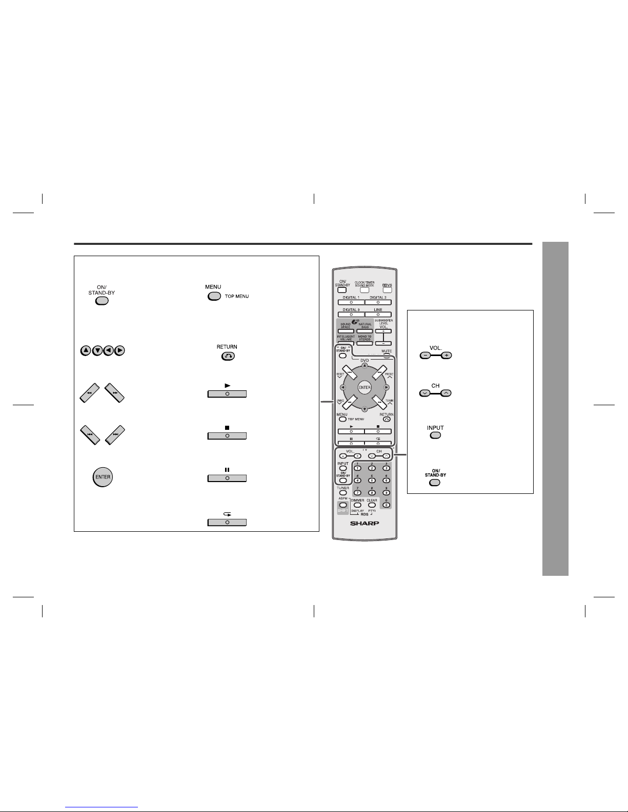
1. Remote Control Transmitter . . . . . . . . . . . . . . . . . . . . . . . . . . . . . . 17
2. ON/STAND-BY button . . . . . . . . . . . . . . . . . . . . . . . . . . . . . . . . . . . 17
3. Input Select Buttons . . . . . . . . . . . . . . . . . . . . . . . . . . . . . . . . . . . . 20
4. Audistry Sound Mode Buttons . . . . . . . . . . . . . . . . . . . . . . . . . . . . 24
5. Tuner Preset Down Button . . . . . . . . . . . . . . . . . . . . . . . . . . . . 27, 28
6. DVD Player Operation Buttons . . . . . . . . . . . . . . . . . . . . . . . . . . . . 35
7. Tuning Down Button . . . . . . . . . . . . . . . . . . . . . . . . . . . . . . . . . . . . 26
8. TV Operation Buttons . . . . . . . . . . . . . . . . . . . . . . . . . . . . . . . . . . . 35
9. Tuner Button . . . . . . . . . . . . . . . . . . . . . . . . . . . . . . . . . . . . . . . . . . 26
10.Shift Button . . . . . . . . . . . . . . . . . . . . . . . . . . . . . . . 18, 26, 28, 32, 35
11.Dimmer Button . . . . . . . . . . . . . . . . . . . . . . . . . . . . . . . . . . . . . . . . . 18
12.Preset Sound Mode / Clock / Timer Button . . . . . . . . . . . . . . . 19, 22
13.Dolby Virtual Speaker Button . . . . . . . . . . . . . . . . . . . . . . . . . . . . . 23
14.Volume Up and Down/
Subwoofer Level Up and Down Buttons . . . . . . . . . . . . . . . . . . . . 18
15.Mute/Display Button . . . . . . . . . . . . . . . . . . . . . . . . . . . . . . . . . . . . 18
16.Tuner Preset Up Button . . . . . . . . . . . . . . . . . . . . . . . . . . . . . . . 27, 28
17.Tuning Up Button . . . . . . . . . . . . . . . . . . . . . . . . . . . . . . . . . . . . . . . 26
18.Direct Number Buttons . . . . . . . . . . . . . . . . . . . . . . . . . . . . . . . 35, 37
19.Clear Button . . . . . . . . . . . . . . . . . . . . . . . . . . . . . . . . . . . . . . . . . . . 31
20.RDS ASPM Button . . . . . . . . . . . . . . . . . . . . . . . . . . . . . . . . . . . . . . 28
21.RDS Display Button . . . . . . . . . . . . . . . . . . . . . . . . . . . . . . . . . . . . . 28
22.RDS PTYI Button . . . . . . . . . . . . . . . . . . . . . . . . . . . . . . . . . . . . . . . 28
2
112
15
5
7
16
17
13
14
3
4
6
10
9
8
11
19
18
21 22
20

9
AN-PR1000_EN.fm06/3/14
AN-PR1000H
TINSEA127AWZZ
2
3
4
5
6
7
8
1
General Information
DVD Player Operation Buttons (Page 35 - 36)
ON/STAND-BY button Menu/Top Menu Button
Sets the DVD power to
"ON" or "STAND- BY".
Press to display the
menu.
TV Operation Buttons
(Page 35)
Cursor Buttons Return Button Volume Up and Down Buttons
Press the button to se-
lect menus and items.
Press the button to re-
turn to the previous
step.
Turn down/up the TV vol-
ume.
Review/Cue Buttons Play Button Channel Up and Down Buttons
Press to go backward
or forward (search).
Play back the DVD
player.
Switch down/up the TV
channels.
Chapter (Track) Skip Down/Up Buttons Stop Button Input Select Button (TV/VCR)
Skip down/up the DVD
chapters (tracks).
Stops the DVD player. Press the button to switch
the input source.
Enter Button Pause Button ON/STAND-BY button
Press to set a menu or
an item.
Press to pause. Sets the TV power to
"ON" or "STAND-BY".
Repeat Play Button
Press to repeat play-
back.

AN-PR1000_EN.fm06/3/14 TINSEA127AWZZ
10
AN-PR1000_EN.fm06/3/14
AN-PR1000H
TINSEA127AWZZ
Preparation for Use
System connections
Installing the main unit and the subwoofer
1. Pull up both speakers outwards.
2. Pre-faster the screw to the speaker box.
3. Snap the metal frame onto the screw and fasten the screw fully. Then turn the unit.
4. Stick the metal frame cushion onto the metal frame and place the glass shelf on top
of it.
Notes:
It is advisable for the top glass cover to be carried by 2 persons.
Top glass with sticker on its surface, must face outwards.
Aerial connection
Note:
Placing the aerial on the unit or near the AC power lead may cause noise pickup.
Place the aerial away from the unit for better reception.
External FM aerial
Use an external FM aerial if you require better reception. Consult your dealer.
Note:
When an external FM aerial is used, disconnect the supplied FM aerial wire.
Top glass cover cushion
Metal frame cushion
Glass shelf
Top glass cover
Sticker up side
Sticker up side
Supplied FM aerial:
Connect the FM aerial wire to the FM 75 OHMS socket
and position the FM aerial wire in the direction where
the strongest signal can be received.
FM
aerial
External
FM aerial
75 ohms
coaxial cable

11
AN-PR1000_EN.fm06/3/14
AN-PR1000H
TINSEA127AWZZ
2
3
4
5
6
7
8
1
Preparation for Use
Subwoofer connection
1. Connect the wire to the speaker terminal.
Using other subwoofer
You can connect a subwoofer with an amplifier to the SUBWOOFER PRE OUT sock-
et.
Notes:
No sound is heard from the subwoofer without a built-in amplifier.
When not using the supplied subwoofer, disconnect the speaker wire from the main
unit.
You may use the supplied subwoofer and a powered subwoofer at the same time.
Make sure to leave the AC power lead disconnected when connecting the sub-
woofer.
Speaker wire
Speaker terminal
Main unit
To SUBWOOFER PRE
OUT socket
To audio input socket
Audio cable
(commercially
available) Audio signal
Commercially available subwoofer
(amplifier built in)

AN-PR1000_EN.fm06/3/14 TINSEA127AWZZ
12
AN-PR1000_EN.fm06/3/14
AN-PR1000H
TINSEA127AWZZ
Preparation for Use
System connections (continued)
Placing the TV or other equipment
1. Please ensure that the equipment is positioned in a well-ventilated area and ensure
that there is at least 10 cm (4") of free space along the sides and back of the
equipment.
2. Placing the TV, DVD player and etc equipment. Please use anti-slip TV cushion to
prevent fall.
Caution:
Before moving the TV away, please ensure that the anti-slip cushions underneath it
have been taken out. This is to prevent the top glass cover from falling as it might stick
to the TV during shifting.
Video deck
DVD player
Stick the anti-slip
cushions (4 pcs)
underneath the TV.
(not included in accessory)
TV
Anti-slip
cushions

13
AN-PR1000_EN.fm06/3/14
AN-PR1000H
TINSEA127AWZZ
2
3
4
5
6
7
8
1
Preparation for Use
Falling prevention
Safety wires are useful to prevent the TV from falling off in case of earthquake occurance.
Pull out the rubber
blocker located
behind the TV.
There is a small hole to
fix the screw in.
Screw
Washer
Screw
Washer
Safety wire
1
2
3
Fix the washer and screws behind the TV.
Hang the safety wire on the screw,
between the washer and the TV.
Tighten the screw in.
At the back of the rack unit,
fix in the washer and the
screw.
4
Put the safety wire around
the screw and washer. Tighten
the screw in.
Loosen the wing nut and pull
the safety wire until it is
stretched properly. Tighten
back the wing nut.
5
Ensure all the screws have
been fixed properly.
6
Ensure all the wing nuts
have been fixed properly.
Wing nut

AN-PR1000_EN.fm06/3/14 TINSEA127AWZZ
14
AN-PR1000_EN.fm06/3/14
AN-PR1000H
TINSEA127AWZZ
Preparation for Use
Audio connections to TVs, DVD players, VCRs, etc.
The drawing below shows the flows of audio and video signals.
Notes:
Refer to the operation manual of the equipment to be connected.
Fully insert the plugs to avoid fuzzy pictures or noises.
Connecting a TV, etc.
Connect to the TV using an optical digital audio cable or an audio cable.
Caution:
Turn off all other equipment before making this connection.
DVD player
VCR
Digital tuner, etc.
TV
Audio signal
Video signal
ON/
STAND-BY VOLUME+
REMOTE
SENSOR
VOLUME–FUNCTION
TIMER
TV
Main unit
Audio cable
(supplied or
commercially
available
)
To audio
output sockets
To OPTICAL
input socket
To optical
digital audio
output socket
Optical digital audio cable
(commercially available)
Audio signal
Audio signal
To LINE
input sockets

15
AN-PR1000_EN.fm06/3/14
AN-PR1000H
TINSEA127AWZZ
2
3
4
5
6
7
8
1
Preparation for Use
Connecting a DVD player, etc.
Connect to the DVD player with an optical digital audio cable or an audio cable.
Note:
Connect the DVD video cable directly to the TV (refer to the operation manual for the
DVD player).
Connecting a VCR, etc.
Connect to the VCR with an audio cable.
Note:
Connect the VCR video cable directly to the TV (refer to the operation manual for the
VCR player).
DVD player
Audio cable
(supplied or
commercially
available)
Optical digital audio cable
(commercially available)
Main unit
To audio
output
sockets
To OPTICAL
input socket
To optical
digital audio
output socket
To the TV (video)
Audio signal
Audio signal
To LINE
input
sockets
To the TV (video)
VCR
Audio cable
(supplied or
commercially
available)
To audio
output sockets
To LINE
input sockets
Main unit
Audio signal

AN-PR1000_EN.fm06/3/14 TINSEA127AWZZ
16
AN-PR1000_EN.fm06/3/14
AN-PR1000H
TINSEA127AWZZ
Preparation for Use
Audio connections to TVs, DVD
players, VCRs, etc. (continued)
Connecting a digital tuner, etc.
Connect to the digital tuner, etc. using an optical digital audio cable or a coaxial digital
audio cable.
Note:
When connecting with an optical digital cable, set the digital output of the digital tuner
to PCM. Refer to the operation manual of the digital tuner.
AC power connection
Connecting the AC power lead
After checking all the connections have been made correctly, connect the AC power
lead to the AC power input socket, then to the wall socket.
Notes:
Never use a power lead other than the one supplied. Otherwise, a malfunction or
an accident may occur.
Unplug the AC power lead from the wall socket if the unit will not be in use for a
prolonged period of time.
To turn the power on
Press the ON/STAND-BY button.
If the power does not turn on, check whether the power lead is plugged in properly.
To set the unit to stand-by mode:
Press the ON/STAND-BY button again.
Note:
After the unit enters the power stand-by mode, wait a few seconds to turn on again.
To the TV (video)
Main unit
Optical digital audio cable
(commercially available)
To OPTICAL
input socket
To optical digital
audio output socket
Coaxial digital
audio cable
(commercially
available)
To coaxial
digital audio
output socket
To COAXIAL
input socket
Audio signal
Audio signal
Wall socket
(AC 220 V- 240 V,
50 Hz)

17
AN-PR1000_EN.fm06/3/14
AN-PR1000H
TINSEA127AWZZ
2
3
4
5
6
7
8
1
Preparation for Use
Remote control
Battery installation
Precautions for battery use:
Replace all old batteries with new ones at the same time.
Do not mix old and new batteries.
Remove the batteries if the unit will not be used for long periods of time. This will
prevent potential damage due to battery leakage.
Caution:
Do not use rechargeable batteries (nickel-cadmium battery, etc.).
Installing the batteries incorrectly may cause the unit to malfunction.
Notes concerning use:
Replace the batteries if the operating distance is reduced or if the operation be-
comes erratic.
Periodically clean the transmitter on the remote control and the sensor on the unit
with a soft cloth.
Exposing the sensor on the unit to strong light may interfere with operation. Change
the lighting or the direction of the unit.
Keep the remote control away from moisture, heat, shock, and vibrations.
Test of the remote control
Point the remote control directly at the remote sensor on the unit.
The remote control can be used within the range shown below:
Press the ON/STAND-BY button. Does the power turn on? Now, you can enjoy your
system.
Use 2 "AAA" size batteries (UM-4, R03, HP-16 or similar).
Batteries are not included.
1 Open the battery cover.
2 Insert the batteries according to the di-
rection indicated in the battery compart-
ment.
When inserting or removing the batteries, push
them towards the battery terminals.
3 Close the cover.
0.2 m - 6 m
(8" - 20')
Remote sensor
ON/
STAND-BY

AN-PR1000_EN.fm06/3/14 TINSEA127AWZZ
18
AN-PR1000_EN.fm06/3/14
AN-PR1000H
TINSEA127AWZZ
Preparation for Use
General control
Volume control
Muting
Notes:
When you press another button, muting is cancelled. However, it is not cancelled if
a button on the TV or DVD player is pressed or the DISPLAY button is pressed with
the SHIFT button down.
When the unit is turned off and back on again, muting is cancelled.
Subwoofer level control
The subwoofer level can be adjusted.
Notes:
When sound from the subwoofer is distorted, decrease the subwoofer level.
When changing the subwoofer level, the output level of the SUBWOOFER PRE
OUT is also changed.
To change the display brightness (2 levels)
Display control
Notes:
If clock not being set before, "ADJUST" will be display for a whilst.
Whilst the time display (within 5 seconds), press the DISPLAY button whilst holding
down the SHIFT button again to cancel the time display manually.
Main unit operation:
Press the VOL + button to increase the volume
and the VOL - button for decreasing.
Remote control operation:
Press the VOL. + button to increase the volume
and the VOL. - button for decreasing.
The volume is muted temporarily when pressing
the MUTE button on the remote control.
Press again to restore the volume.
To increase the level, hold down the SHIFT button
and press the SUBWOOFER LEVEL + button.
To decrease the level, hold down the SHIFT button
and press the SUBWOOFER LEVEL - button.
You can switch the display brightness by pressing
the DIMMER button.
This unit clock can be display during power On/Off.
Display clock:
Whilst holding down the SHIFT button, press the
DISPLAY button. The time display will appear for
about 5 seconds.
00 01 403902.....
-
8
-7
8
7
.....

19
AN-PR1000_EN.fm06/3/14
AN-PR1000H
TINSEA127AWZZ
2
3
4
5
6
7
8
1
Preparation for Use
Setting the clock
By setting the unit to the correct time, you can use it not only as a clock but also for
timer playback.
You can set the clock even when the unit is in the stand-by mode.
In this example, the clock is set for the 24-hour (0:00) display
Note that this can only be set when the unit is first installed or it has been reset (see
page 40).
To confirm the time display:
Hold down the SHIFT button and press the DISPLAY button.
The time display will appear for about 5 seconds.
Note:
The "ADJUST" or time will flash at the push of the SHIFT and DISPLAY buttons when
the AC power supply is restored after a power failure or unplugging the unit.
To readjust the clock:
Perform "Setting the clock" from step 1. If the "ADJUST" is not flashing in step 1, step
2 (for selecting the 24-hour or 12-hour display) will be skipped.
To change the 24-hour or 12-hour display:
1 Clear all the programmed contents. [Refer to "Clearing all the memory (reset)" on
page 40 for details].
2 Perform "Setting the clock" from the beginning.
1Hold down the SHIFT button and press the CLOCK button. Within
5 seconds, press the or button to select CLOCK ADJUST and
then press the ENTER button.
2Hold down the SHIFT button and press the or button to select
the 24-hour or 12-hour display and then press the ENTER button.
"0:00" The 24-hour display will appear. (0:00 - 23:59)
"AM 12:00" The 12-hour display will appear. (AM 12:00 - PM 11:59)
"AM 0:00" The 12-hour display will appear. (AM 0:00 - PM 11:59)
3Hold down the SHIFT button and
press the or button to adjust the
hour and then press the ENTER
button.
Press the or button once to advance the time by 1 hour. Hold it down to
advance continuously.
When the 12-hour display is selected, "AM" will change automatically to "PM".
4Hold down the SHIFT button and
press the or button to adjust the
minutes and then press the ENTER
button.
Press the or button once to advance the time by 1 minute. Hold it down
to advance continuously.
The hour will not advance even if minutes advance from "59" to "00".
The clock starts from "0" second (seconds are not displayed).
The time disappears after approx.5 seconds.

AN-PR1000_EN.fm06/3/14 TINSEA127AWZZ
20
AN-PR1000_EN.fm06/3/14
AN-PR1000H
TINSEA127AWZZ
Basic Operation
Listening to the playback sound from DVD players, VCRs, etc.
ON/
STAND-BY
1Turn on the connected equipment.
2Press the ON/STAND-BY button to turn the power on.
3Select the source to be played back.
Remote control operation:
To select a digital source, press the corresponding button.
Press the LINE button repeatedly to select the LINE input.
Main unit operation:
Press the FUNCTION button repeatedly to select a source.
4Press the play button of the connected equipment.
5Adjust the volume level with the VOLUME control (see page 18).
6Enjoy surround sound or various sound qualities (see pages 21 -
25).
7After use:
Press the ON/STAND-BY button to enter the power stand-by mode.
Note:
Reduce the volume level with the VOLUME control before entering the power
stand-by mode.
LINE 1
LINE 2
LINE 3
DIGITAL 1
DIGITAL 2
DIGITAL 3
DIGITAL 1FM Mono
FM ST
DIGITAL 2 DIGITAL 3
LINE 3 LINE 2 LINE 1
Other manuals for AN-PR1000H
2
Table of contents
Other Sharp Home Theater System manuals

Sharp
Sharp HT-SB20 User manual

Sharp
Sharp HT-SB110 User manual

Sharp
Sharp CD-DVD500 User manual

Sharp
Sharp AN-PR1500H User manual

Sharp
Sharp HT-DD5000 User manual

Sharp
Sharp HT-CN300 User manual

Sharp
Sharp HT-SB603 User manual

Sharp
Sharp HT-DV40H User manual

Sharp
Sharp HT-SB600 User manual

Sharp
Sharp HT-M700H User manual

Sharp
Sharp HT-SB60 User manual

Sharp
Sharp HT-SB40 User manual

Sharp
Sharp HT-SB40 User manual

Sharp
Sharp SD-AT100W User manual

Sharp
Sharp HT-DV50H User manual

Sharp
Sharp SD-AT50H User manual

Sharp
Sharp HT-SL50 User manual

Sharp
Sharp HT-CN400DVE User manual

Sharp
Sharp HT-CN300H User manual

Sharp
Sharp HT-SB602 User manual