Sharp XL-30V User manual

– 1 –
XL-30V
CONTENTS
Page
SAFETY PRECAUTION FOR SERVICE MANUAL .............................................................................................................2
VOLTAGE SELECTION.......................................................................................................................................................2
AC POWER SUPPLY CORD AND AC PLUG ADAPTOR ...................................................................................................2
SPECIFICATIONS ...............................................................................................................................................................3
NAMES OF PARTS .............................................................................................................................................................4
OPERATION MANUAL ........................................................................................................................................................6
DISASSEMBLY................................................................................................................................................................... 8
REMOVING AND REINSTALLING THE MAIN PARTS.................................................................................................... 10
ADJUSTMENT .................................................................................................................................................................. 12
TEST MODE ..................................................................................................................................................................... 15
ERROR LIST..................................................................................................................................................................... 17
NOTES ON SCHEMATIC DIAGRAM ............................................................................................................................... 19
TYPES OF TRANSISTOR AND LED................................................................................................................................ 19
BLOCK DIAGRAM ............................................................................................................................................................ 20
SCHEMATIC DIAGRAM / WIRING SIDE OF P.W.BOARD.............................................................................................. 26
VOLTAGE ......................................................................................................................................................................... 40
WAVEFORMS OF CD CIRCUIT....................................................................................................................................... 41
TROUBLESHOOTING ...................................................................................................................................................... 42
FUNCTION TABLE OF IC................................................................................................................................................. 49
LCD SEGMENT ................................................................................................................................................................ 62
PARTS GUIDE/EXPLODED VIEW
SERVICE MANUAL
SHARP CORPORATION
No. S0081XL30V///
• In the interests of user-safety the set should be restored to its original
condition and only parts identical to those specified should be used.
This document has been published to be used
for after sales service only.
The contents are subject to change without notice.
NTSC/PAL
XL-30V
XL-30V Video CD Micro System consisting of XL-30V (main unit)
and CP-XL30V (speaker system).
MODEL
VIDEO CD MICRO SYSTEM

XL-30V
– 2 –
CAUTION
●This Video CD Micro System is classified as
a CLASS 1 LASER product.
●The CLASS 1 LASER PRODUCT label is lo-
cated on the rear cover.
●Use of controls or adjustments or perform-
ance of procedures other than those speci-
fied herein may result in hazardous radiation
exposure.
As the laser beam used in this compact disc
player is harmful to the eyes, do not attempt
to disassemble the cabinet. Refer servicing
to qualified personnel only.
Laser Diode Properties
Material: GaAIAs
Wavelength: 780 nm
Emission Duration: continuous
Laser Output: max. 0.6 mW
CAUTION-INVISIBLE LASER RADIATION WHEN OPEN. DO NOT STARE INTO
BEAM OR VIEW DIRECTLY WITH OPTICAL INSTRUMENTS.
VARNING-OSYNLIG LASERSTRALNING NAR DENNA DEL AR OPPNAD. STIRRA
EJ IN I STRALEN OCH BETRAKTA EJ STRALEN MED OPTISKA INSTRUMENT.
ADVERSEL-USYNLIG LASERSTRALING VED ABNING. SE IKKE IND I
STRALEN-HELLER IKKE MED OPTISKE INSTRUMENTER.
VARO! AVATTAESSA OLET ALTTIINA NAKYMATON LASERSATEILYLLE.
ALA TUIJOTA SATEESEEN ALAKA KATSO SITA OPTISEN LAITTEEN LAPI.
VARNING-OSYNLIG LASERSTRALNING NAR DENNA DEL AR OPPNAD.
STIRRA EJ IN I STRALEN OCH BETRAKTA EJ STRALEN GENOM OPTISKT
INSTRUMENT.
ADVERSEL-USYNLIG LASERSTRALING NAR DEKSEL APNES. STIRR IKKE
INN I STRALEN ELLER SE DIREKTE MED OPTISKE INSTRUMENTER.
Precaution to be taken when replacing and servicing the Laser Pickup.
The AEL (Accessible Emission Level) of Laser Power Output for this model is specified to be lower than Class 1 Requirements.
However, the following precautions must be observed during servicing to protect your eyes against exposure to the Laser beam
(1) When the cabinet has been removed, the power is turned on without a compact disc, and the Pickup is on a position outer than
the lead-in position, the Laser will light for several seconds to detect a disc. Do not look into the Pickup Lens.
(2) TheLaserPowerOutputofthePickupinsidetheunitandreplacementservicepartshavealreadybeenadjustedpriortoshipping.
(3) No adjustment to the Laser Power should be attempted when replacing or servicing the Pickup.
(4) Under no circumstances look directly into the Pickup Lens at any time.
(5) CAUTION - Use of controls or adjustments, or performance of procedures other than those specified herein may result in
hazardous radiation exposure.
SAFETY PRECAUTION FOR SERVICE MANUAL
VOLTAGE SELECTION
Before operating the unit on mains, check the preset voltage. If the voltage is different from your local voltage, adjust the voltage
as follows, turn the selector with a screwdriver until the appropriate voltage number appears in the window (110V - 127 V or
220 V - 240 V AC).
AC POWER SUPPLY CORD AND AC PLUG ADAPTOR
QACCE0001SJ00
QACCA0001SJ00
QACCB0001SJ00 QPLGA0253AFZZ

– 3 –
XL-30V
●Cassette deck section
Frequency response: 50 - 14,000 Hz (Normal tape)
Signal/noise ratio: 50 dB
Wow and flutter: 0.25 % (WRMS)
Type: Full range speaker system
Speakers: 10 cm (4") full-range speaker
Rated input power: 5 W
Maximum input power: 10 W
Impedance: 4 ohms
Dimensions: Width; 145 mm (5-3/4")
Height; 240 mm (9-1/2")
Depth; 191 mm (7-9/16")
Weight: 1.5 kg (3.3 lbs.)/each
●General
●Amplifier section
● Tuner section
Frequency range: FM; 88-108 MHz
AM; 531-1,602 kHz
●Compact disc player section
Type: Compact disc player
Signal readout: Non-contact, 3-beam semi-
conductor laser pickup
D/A converter: 1-bit D/A converter
Filter: 8-times oversampling digital
filter
Frequency response: 20 - 20,000 Hz
Wow and flutter: Unmeasurable
(
less than 0.001% W. peak
)
Output terminals: Speakers; 4 ohms
Headphones; 16 - 50 ohms
(recommended; 32 ohms)
Output power: MPO; 14 W (7 W + 7 W)
(10 % T.H.D.)
RMS; 10 W (5 W + 5 W)
(10 % T.H.D.)
Power source: AC 110 - 127/220 - 240 V,
50/60 Hz
Power consump-
tion: 35 W
Dimensions: Width; 160 mm (6-5/16")
Height; 241 mm (9-1/2")
Depth; 249 mm (9-13/16")
Weight: 3.1 kg (6.8 lbs.)
Video out: 1 Vp-p (75 ohms)
● Video CD section
Video output
format: PAL / NTSC
FOR A COMPLETE DESCRIPTION OF THE OPERATION OF THIS UNIT, PLEASE REFER
TO THE OPERATION MANUAL.
SPECIFICATIONS
XL-30V
Specifications for this model are subject to change without
prior notice.
CP-XL30V

XL-30V
– 4 –
Rear panel
1. Voltage Selector
2. AC Power Input Socket
3. FM 75 ohms Aerial Socket
4. AM Loop Aerial Socket
5.
25. Volume/Jog Dial
26. (VCD) Skip/Next Button
(CD) Track Up Button
(TAPE) Fast Forward Button
(TUNER) Tuning Up Button
27. Volume/Jog Dial Selector Button
28. Cassette Compartment
Front panel
1. Timer Indicator
2. Record Indicator
3. Sleep Indicator
4. (VCD/CD) Repeat Indicator
5. (VCD/CD) Play Indicator
6. (VCD/CD) Random Indicator
7. (VCD/CD/TUNER) Memory Indicator
8. FM Stereo Mode Indicator
9. FM Stereo Indicator
10. VCD/CD Compartment
11. On/Stand-by Button
12. (VCD) Stop/Return Button
(CD/TAPE) Stop Button
(TUNER) Memory Clear Button
13. (TAPE) Record Pause Button
14. Bass/Treble Selector Button
15. Memory/Set Button
16. Clock/Timer/Sleep Button
17. Band Selector Button
18. (VCD) Skip/Previous Button
(CD) Track Down Button
(TAPE) Rewind Button
(TUNER) Tuning Down Button
19. Function Selector Button
20. Headphones Socket
21. (VCD/CD) Eject Button
22. Remote Control Sensor
23. Volume Select Button
24. (VCD/CD/TAPE) Play Button
5. Video Output Socket
6. SpeakerTerminals
123
46789
5
10
11
12
13
14
15
16
21
22
23
24
25
26
27
28
17
18
19
20
2
1
4
3
6
5
NAMES OF PARTS
XL-30V

– 5 –
XL-30V
CP-XL30V
XL-30V
Remote control
1. Bass Reflex Duct
2. Full-Range Speaker
3. Speaker Wire
1
2
3
1. Remote ControlTransmitter LED
2. Timer Button
3. (VCD/CD) Audio Mode Button
4. (VCD/CD) Direct Search Buttons
5. (VCD/CD) Display Button
6. (VCD)Video Intro Button
7. Sleep Button
8. On/Stand-by Button
9. (VCD)TVType Button
10. (VCD)Track Digest Button
11. (VCD) Time Search Button
12. (VCD/CD) Memory Button
13. (VCD/CD) Clear Button
14. (VCD/CD) Random Button
15. (VCD) Playback Control Auto/Off Button
16. (VCD) Skip/Previous Button
(CD)Track Down Button
17. (VCD) Skip/Next Button
(CD)Track Up Button
18. (VCD/CD) Repeat Button
19. (VCD/CD) Pause Button
20. (VCD/CD) Review Button
(TAPE) Rewind Button
21. (VCD/CD) Cue Button
(TAPE) Fast Forward Button
22. (VCD) Stop/Return Button
(CD/TAPE) Stop Button
23. (VCD/CD/TAPE) Play Button
24. (TAPE) Record Pause Button
25. Function Buttons
26. Treble Buttons
27. Bass Buttons
28. (TUNER) Preset Up/Down Buttons
29. Volume Up/Down Buttons
12 13 14 15
1
2
3
4
5
6
7
8
9
10
11
16 17 1918
20 21 22 23
24
25
26
27
28
29

XL-30V
– 6 –
OPERATION MANUAL
PREPARATION FOR USE PREPARATION FOR USE
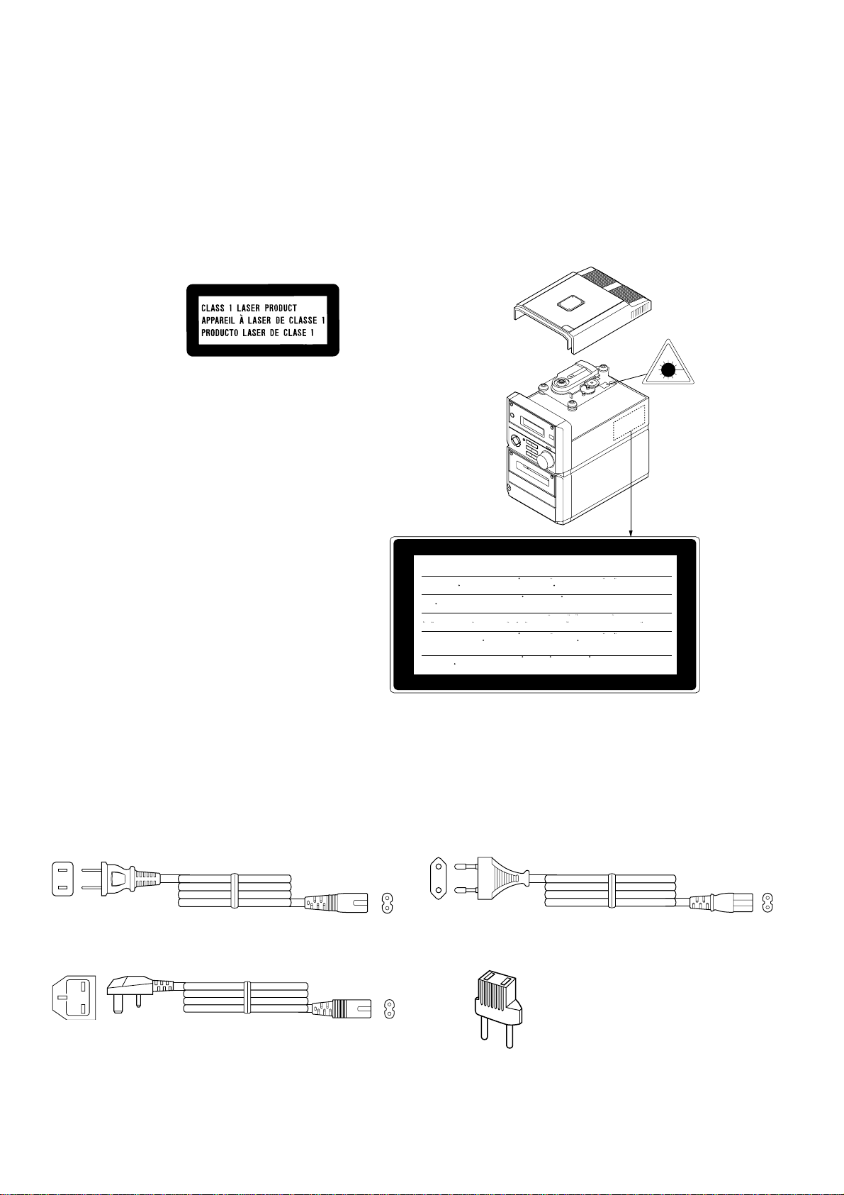
■Connecting the AC power lead
Check thesetting of theAC voltage selector located
on the rear panel before plugging the unit into an
AC socket. If necessary, adjust the selector to cor-
respond totheAC power voltage usedin your area.
Selector adjustment:
Turn the selector with a screwdriver until the ap-
propriate voltage number appears in the window
(110V - 127V or 220V - 240V AC).
Notes:
●Unplug theAC power lead from the AC socket if
the unit is not to be used for a prolonged period
of time.
●Never use a power lead other than the one sup-
plied.
Otherwise, a malfunction or an accident may
occur.
●AC Plug Adaptor
In areas (or countries) where an AC socket as
shown in illustration
2
is used, connect the unit
using the AC plug adaptor supplied with the unit,
as illustrated. The AC plug adaptor is not included
in areas where the AC wall socket and AC power
plug can be directly connected (see illustration
1
).
Note for users in Australia and New Zealand:
An AC plug adaptor is not supplied if the lead has
an Australian Standard plug.
1
2
RATED
LINE VOLTAGE
220V
ı
240V
To an AC socket
Precautions for battery use:
●Insertthe batteries according to the direction in-
dicated in the battery compartment.
●Replace all old batteries with new ones at the
same time.
●Do not mix old and new batteries.
●Remove the batteries if they are weak or if the
unit willnot beused for long periodsof time.This
willprevent potentialdamagedueto batteryleak-
age.
Caution:
Do notuse rechargeable batteries(nickel-cadmium
battery, etc.).
Notes concerning use:
●Replace the batteries ifthe operating distance is
reduced or if the operation becomes erratic.
●Periodically clean the transmitter LED on the re-
mote control and the sensor on the main unit
with a soft cloth.
●Exposing the sensor on the main unit to strong
light may interfere with operation. Change the
lighting or the direction of the unit.
●Keep the remote control away from moisture,
excessive heat, shock, and vibrations.
■Remote control
15
15
●2 “AA” size batteries (UM/SUM-3, R6, HP-7
or similar)
0.2m - 6m
(8"- 20')
●When inserting or removing the batteries, push
them towards the battery terminals.
●Installing thebatteries incorrectlymay causethe
unit to malfunction.
-
■AM/FM interval (span)
The International Telecommunication Union (ITU)
has established that member countries should
maintain either a 10 kHz or a 9 kHz interval be-
tween broadcasting frequencies of anyAM station.
The illustration shows the 9 kHz interval zones (re-
gions 1 and 3), and the 10 kHz interval zone (re-
gion 2).
This product is not equipped with a span selector.
However, it will be adjusted to 9 kHz AM interval
(50 kHz FM interval) when shipped from the fac-
tory.
Before using the unit, be sure to set it for the AM
tuning interval (span) used in your area.
To check the tuning span currently selected:
1
Press the ON/STAND-BY button to turn the
power on.
2
Press the FUNCTION button until “FM” or
“AM” appears in the display.
3
Press the BAND button to select the AM
band.
●If “AM 531 kHz” is displayed, it means that the
radio has been adjusted for a 9 kHz span. If “AM
530 kHz” is displayed, it means that the radio
has been adjusted for a 10 kHz span.
To change from a 9 kHz AM (50 kHz FM) interval
to a 10 kHz AM (100 kHz FM) interval:
1
Press the ON/STAND-BY button to enter the
stand-by mode.
2
Hold down the button and the MEMORY/
SET button for at least 4 seconds. Release
the buttons when “AM SP 10 kHz” and “FM
SP 100 kHz” are displayed alternately.
●The unit will return to the clock display.
To return to a 9 kHz AM (50 kHz FM) interval:
1
Press the ON/STAND-BY button to enter the
stand-by mode.
2
Hold down the button and the MEMORY/
SET button for at least 4 seconds. Release
the buttons when “AM SP 9 kHz” and “FM
SP 50 kHz” are displayed alternately.
●The unit will return to the clock display.
Caution:
●When the unit is left for a few hours after the
span has been switched andAC power lead dis-
connected, it will be automatically returned to a
9 kHz span. If this happens, set the span again.
●When the span is switched, any stations that are
memorised will be cancelled.
MEMORY/
SET
FUNCTION
BAND
ON/
STAND-BY
kHz
kHz kHz
kHz
kHz
kHz kHz
kHz

– 7 –
XL-30V
SETTING THE CLOCK RESETTING THE MICROCOMPUTER
(Main unit operation)
1
Press the CLOCK/TIMER/SLEEP button.
2
Within 3 seconds, press the MEMORY/SET
button.
3
Turnthejogdialtoselectthetime displaymode.
0:00 AM 12:00
“0:00” →The 24-hour display will appear.
(0:00 - 23:59)
“AM 12:00” →The 12-hour display will appear.
(AM 12:00 - PM 11:59)
●Note that this can only be set when the unit is
first installed or it has been reset.
4
Press the MEMORY/SET button.
5
Adjust the hour by turning the jog dial.
●When the jog dial is turned one click clockwise,
thetimewill increase by1hour.When it isturned
one click anti-clockwise, the time will decrease
by 1 hour.
Keepturningthe jog dialtochange the time con-
tinuously.
●When the 12-hour display is selected, “AM” will
change automatically to “PM”.
7
Adjust the minutes by turning the jog dial.
●When the jog dial is turned one click clockwise,
the time will increase by 1 minute. When it is
turned one click anti-clockwise, the time will de-
crease by 1 minute.
Keepturningthe jog dialtochange the time con-
tinuously.
●The hour setting will not advance even if min-
utes advance from “59” to “00”.
8
Press the MEMORY/SET button.
●The clock starts operating from “0” seconds.
(Seconds are not displayed.)
Note:
●The clock display will flash on and off when the
AC power supply is restored after a power fail-
ure occurs or after the AC power lead is discon-
nected.
If this happens, follow the procedure below to
change the clock time.
To change the clock time:
Perform steps 1, 2 and 5 - 8 above.
To change the time display mode:
➀Perform steps 1 - 3 in the section “RESETTING
THE MICROCOMPUTER”.
➁Perform steps 1 - 8 above.
In this example, the clock is set for the 24-hour
(0:00) system.
6
Press the MEMORY/SET button.
CLOCK/TIMER/
SLEEP
MEMORY/SET
Jog dial
Reset the microcomputer under the following
conditions:
●To erase allofthestored memory contents (clock
and timer settings, and tuner and CD presets).
●If the display is not correct.
●If the operation is not correct.
1
Press the ON/STAND-BY button to enter the
stand-by mode.
2
Unplug the AC power lead from the AC IN-
PUT socket on this unit.
3
Whilst pressing down the MEMORY/SET but-
ton and the button, plug the AC power lead
into the AC INPUT socket on this unit.
Caution:
●Theoperationexplained above willerasealldata
stored in memory, such as clock and timer set-
tings, and tuner and CD presets.
1
33
AC INPUT
2,3

XL-30V
– 8 –
1 Side Panel 1. Screw ................. (A1) x8 8-1
(Left/Right)
2 Top Cabinet 1. Screw ................. (B1) x1 8-1
2. Socket ................ (B2) x5
3 Rear Panel 1. Screw ................. (C1) x3 8-1
4 Main PWB/ 1. Screw ................. (D1) x2 8-2
Headphones PWB 2. Screw ................. (D2) x3
3. Bracket ............... (D3) x1
4. Socket ................ (D4) x3
5. Flat wire.............. (D5) x1
6. Socket ................ (D6) x1
5 Jog Switch PWB 1. Socket ................ (E1) x1 8-2
2. Screw ................. (E2) x2
6 Display PWB/ 1. Screw ................. (F1) x3 8-2
LED PWB 2. Screw ................. (F2) x3
(With Jog Motor 3. Bracket ............... (F3) x1
Holder) 4. Socket ................ (F4) x1
3. Knob ................... (F5) x1
6. Hook ................... (F6) x2
7. Hook ................... (F7) x2
7 Front Panel 1. Screw ................. (G1) x1 8-2
2. Socket ................ (G2) x1
3. Screw ................. (G3) x1
8 Power PWB 1. Screw ................. (H1) x4 8-2
2. Screw ................. (H2) x1
3. Screw ................. (H3) x1
4. Bracket ............... (H4) x1
9 Tape Mechanism 1. Open the cassette holder. 8-3
2. Screw ................. (J1) x4
10 Video PWB 1. Screw ................. (K1) x4 8-4
2. Socket ................ (K2) x3
11 CD PWB/ 1. Screw ................. (L1) x4 8-4
Open Close Switch 2. Bracket ............... (L2) x3
PWB (Note) 3. Hook ................... (L3) x2
4. Socket ................ (L4) x3
12 CD Mechanism 1. Screw ................. (M1) x3 8-5
DISASSEMBLY
Figure 8-2
Figure 8-3
STEP REMOVAL PROCEDURE FIGURE
Figure 8-1
XL-30V
XL-30VCaution on Disassembly
Follow the below-mentioned notes when disassembling
the unit and reassembling it, to keep it safe and ensure
excellent performance:
1. Take cassette tape and compact disc out of the unit.
2. Be sure to remove the power supply plug from the wall
outlet before starting to disassemble the unit.
3.Takeoff nylonbandsor wireholderswhere theyneedto
beremovedwhendisassemblingtheunit.Afterservicing
theunit,be suretorearrange theleadswhere theywere
before disassembling.
4. Take sufficient care on static electricity of integrated
circuits and other circuits when servicing.
(A1)x2
ø3x10mm
(B2)x1 (C1)x2
ø3x10mm
Side Panel
(Right)
Front
Panel
Rear Panel (C1)x1
ø3x10mm
Side Panel
(Left)
(B2)x1
(A1)x4
ø3x10mm
(A1)x1
ø3x10mm
(A1)x1
ø3x10mm
(B1)x1
ø3x10mm
Top Cabinet
CD PWB
Display
PWB
Main PWB
(B2)x1 (B2)x2
Power
PWB
(F2)x2
ø2.5x10mm
(F2)x1
ø2.5x10mm
(F1)x3
ø2.5x14mm
(E2)x2
ø2.5x12mm
(D2)x1
ø3x8mm
(D2)x1
ø3x8mm
Main PWB
Power PWB
Front Panel
Display PWB
LED
PWB
(H1)x4
ø3x6mm
(D2)x1
ø3x8mm
(D3)x1
(G2)x1
(H2)x1
ø3x10mm
(G1)x1
ø3x8mm
(G3)x1
ø3x6mm
(D4)x1
(D4)x1
(F3)x1
(D5)x1
(F6)x2
(F7)x2
(F5)x1
(D4)x1
Tape
Mechanism
PWB
(F4)x1
Headphones
PWB
(E1)x1
(D1)x2
ø3x10mm
Jog Motor
Holder
Jog Switch
PWB
(D6)x1
Power PWB
Sub Power
Transformer
(H3)x1
ø3x6mm
(H4)x1
Tape
Mechanism
Open
(J1)x4
ø2.5x10mm
Front Panel
Cassette
Holder
Note:
After removing the connector for the optical pickup from the
connector, wrap the conductive aluminium foil around the
front end of connector remove to protect the optical pickup
from electrostatic damage.

– 9 –
XL-30V
Figure 9-1 Figure 9-2
1 Woofer 1. Front panel .......... (A1) x1 9-3
2. Screw .................. (A2) x4
STEP REMOVAL PROCEDURE FIGURE
CP-XL30V
Figure 9-3
(L4)x1
(L3)x2 (L4)x2
(L2)x1
(L2)x1
Top Cabinet
CD PWB
Open/Close
Switch PWB
CD Motor PWB CD Mechanism
(L2)x1
(L1)x4
ø2.5x14mm
(K1)x4
ø2x10mm
(K2)x1 (K2)x2
Video PWB
CD Mechanism
(M1)x3
ø2.5x10mm
PWB Washer x3
Top Cabinet
(A2)x4
ø4x12mm
(A1)x1
Woofer Speaker Box
Screwdriver
Direction of handle
Driver should be
pried away from
speaker Box.

XL-30V
– 10 –
(D1)x1
ø2x4mm
(D2)x3
Special
Screw
Motor
Bracket
Motor
Motor
(D1)x1
ø2x4mm
Main Belt
(C1)x1
FF/REW Belt
(C2)x1
REW/FF
Clutch
Motor
<A>
Pinch Roller
(B1)x1 Pinch Roller
Pawl
Erase Head
Record/
Playback Head
(A1)x2
ø2x8mm
(A2)x1
ø2x3mm
(A2)x1
ø2x7mm
TAPE MECHANISM SECTION
Perform steps 1 to 7 and 9 of the disassembly method to
remove the tape mechanism. (See page 8.)
How to remove the record / playback and erase
heads (See Fig. 10-1.)
1.Removethescrews(A1)x2pcs.,toremovetheerasehead.
2. Remove the screws (A2) x 2 pcs., to remove the record/
playback head.
Note:
After replacing the heads and performing the azimuth
adjustment, be sure to apply screw lock.
How to remove the pinch roller (See Fig. 10-2.)
1. Carefully bend the pinch roller pawl in the direction of the
arrow <A>, and remove the pinch roller (B1) x 1 pc.,
upwards.
How to remove the belts (See Fig. 10-3.)
1. Remove the main belt (C1) x 1 pc., from the motor pulley.
2. Remove the FF/REW belt (C2) x 1 pc., from the REW/FF
clutch.
3. Put on the belts in the reverse order of removal.
Note:
Whenputtingon thebelt,ascertain thatthebelt isnottwisted,
and clean it.
How to remove the motor (See Fig. 10-4.)
1. Remove the main belt.
2. Remove the screws (D1) x 2 pcs., to remove the motor
bracket.
3. Remove the screws (D2) x 3 pcs., to remove the motor.
Note:
Whenmountingthemotor,payattentiontothemotormounting
angle.
Figure 10-1
Figure 10-2
Figure 10-3
Figure 10-4
REMOVING AND REINSTALLING THE MAIN PARTS

– 11 –
XL-30V
Pickup Unit
(A2) x2
ø2.6 x6mm
(A1) x2
CD Mechanism
Shaft
(A3) x1
Gear
(A5) x1
Stop Washer
(A4) x1
Mechanism Cover
(A1) x2
(G2)x2
ø2x5mm
Worm
Gear Jog Belt
(G1)x1 Jog Motor
Holder
Jog Motor
Display PWB
Tape
Mechanism
PWB Tape
Mechanism
PWB
(F3)x2
Solder
Joint
(F2)x1
ø2x8mm
(F1)x1
ø2x3mm
Stop
Washer Driver
(E1)x1
Stop Washer
Mechanism
Chassis
Washer x 2
Flywheel
Figure 11-4
Figure 11-2
Figure 11-3
Figure 11-1
How to remove the flywheel (See Fig. 11-1.)
1. Remove the belt.
2.Removethestopwasher(E1)x1pc.,withasmallprecision
screwdriver to extract the flywheel from the capstan metal.
Note:
Whenthestopwasherisdeformedordamaged,replaceitwith
a new one.
How to reinstall the parts
Install each part in the reverse order of the removal with care.
How to remove the tape mechanism PWB
(See Fig. 11-2.)
1. Remove the screw (F1) x 1 pc., to remove the tape
mechanism PWB.
2. Remove the screw (F2) x 1 pc.
3. Remove the solder joints (F3) x 2 pcs., to remove the tape
mechanism PWB.
How to remove the jog motor (See Fig. 11-3.)
1. Remove the side panel and top cabinet.
2. Remove the jog belt (G1) x 1 pc., from the motor pulley.
3. Remove the screws (G2) x 2 pcs., to remove the jog motor.
Note:
Whenputtingon thebelt,ascertain that thebelt is nottwisted,
and clean it.
CD MECHANISM SECTION
Perform steps 1, 2, 10, 11 and 12 of the disassembly method
to remove the CD mechanism.
How to remove the pickup (See Fig. 11-4.)
1. Remove the mechanism cover, paying attention to the
pawls (A1) x 4 pcs.
2. Remove the screws (A2) x 2 pcs., to remove the shaft
(A3) x 1 pc.
3. Remove the stop washer (A4) x 1 pc., to remove the gear
(A5) x 1 pc.
4. Remove the pickup.
Note:
After removing the connector for the optical pickup from the
connector, wrap the conductive aluminium foil around the
front end of connector remove to protect the optical pickup
from electrostatic damage.

XL-30V
– 12 –
Figure 12-5
ADJUSTMENT
CD SECTION
Since this CD system incorporates the following automatic
adjustment function, when the pickup is replaced, it is not
necessary to readjust it.
VIDEO CD SECTION
A-BEX
TEST VIDEO CD
Disc Adjusting
Point Instrument
Connection
CD Stop TC100V 27.00000 MHz
1
of R163V and
±160 Hz
2
of C183V
•Measurement of oscillation frequency
•Checking of video output signal
Checking of color bar
Disc Adjusting Point Instrument
Connection
Track 2 Video output terminal Chroma Peak Level
100 ±15 IRE
Figure 12-1 ADJUSTMENT POINTS
Figure 12-2 Measurement of oscillation frequency
Figure 12-4
Figure 12-3 Checking of video output signal
Model No. TVD-581
TVD-581A
Specified Value
SET
VIideo Output Terminal
75 ohms
GND
Vectorscope
Waveform monitor
or oscilloscope
SET
Video Output Terminal
Video Input Terminal
TV
Color bar signal
waveform
100 100 88.5 75 70
75
41.5
33.5
50
-13.5 -25 -25
100 IRE
(0.714V)
(1V)
(0.286V)
140 IRE
Horizontal
sync signal
40 IRE
40 IRE
Color Burst
20
-20
-40
Blue
Red
Green
Magenta
Cyan
Yellow
Gray
(59.94Hz/NTSC)
IH
TV monitor
Blue
Red
Green
Magenta
Cyan
Yellow
Gray
IC15V
IC14V
TC100V
XL100V
C183V
R163V
2
GND
1
PCLK2X
VIDEO PWB

– 13 –
XL-30V
Checking of vector scope waveform
Checking SettingDisc Checking
Item
Track 2 VIDEO OUT Set the phase of Phase check
color burst signal ±10°
(B) to 180°-360°
line.
( Check that the setting is within the illustrated range.)
Figure 13-2
Checking the black-and-white level
Track 16 VIDEO OUT Output level
100 ±10 IRE
Checking Checking ItemDisc
Figure 13-1
YL
MG
CY
G
75% B
R-Y
-Q
-I
[NTSC] [PAL]
I
Q
YL
R
R75%
B-Y
MG
B
CY
cy
Gmg
U
V
g
yl
b
100IRE
40IRE
40IRE
100% Luminance
Horizontal Interval
reference signal 100% WHITE LEVEL

XL-30V
– 14 –
TAPE MECHANISM
M901
Tape
Motor
Variable
resistor
in motor
MECHANISM SECTION
• Driving Force Check
Torque Meter Specified Value
Play: TW-2412 Over 80 g
• Torque Check
Torque Meter
Play: TW-2111 30 to 60 g.cm
Fast forward: TW-2231 55 to 140 g.cm
Rewind: TW-2231 55 to 140 g.cm
Specified
Value
Adjusting
Point Instrument
Connection
Test Tape
Specified Value
• Tape Speed
TUNER SECTION
fL: Low-range frequency
fH: High-range frequency
MTT-111 Variable 3,000 ±90 Hz Headphones
resistor in jack
motor. (M901)
Adjusting
Parts
Display
Frequency
• FM Mute Level
Signal generator: 1 kHz, 40 kHz dev., FM modulated
*1. Adjust so that an output signal appears.
98.00 MHz 98.00 MHz VR351 *1 Input: SO301
(25 dBµV) Output: Speaker
Terminal
Instrument
Connection
AM IF 450 kHz 1,602 kHz T351 *1
AM Band — 531 kHz (fL): T306 *2
Coverage 1.1 ±0.1 V
AM Tracking 990 kHz 990 kHz T302 *1
Test Stage Frequency Frequency
Display Setting/
Adjusting
Parts
Instrument
Connection
• FM RF
Signal generator: 1 kHz, 75 kHz dev., FM modulated
FM Band — 87.50 MHz (fL): L303 *1
Coverage 3.4 ±0.1 V
FM RF 98.00 MHz 98.00 MHz L302 *2
(10~30 dB)
Test Stage Frequency Frequency
Display Setting/
Adjusting
Parts
Instrument
Connection
*1. Input: Antenna Output: TP301
*2. Input: Antenna Output: Speaker Terminal
• FM Detection
Signal generator: 10.7 MHz, FM sweep generator
FM IF 10.7 MHz 98.00 MHz T304 (Turn Input: Pin 1 of
the core of IC301
T304 fully
counter-
clockwise).
Test
Stage Frequency Frequency
Display Setting/
Adjusting
Parts
Instrument
Connection
*1. Input: Antenna Output:SpeakerTerminal
*2. Input: Input is not connected Output: TP301
• AM IF/RF
Signal generator: 400 Hz, 30%, AM modulated
Figure 14-1 ADJUSTMENT POINT
Figure 14-2 ADJUSTMENT POINTS
R336
T306
VR351
T302
T304
L303
IC301
L302
T351
1
9
MAIN PWB
AM ANTENNA
FM Mute
Level
AM IF
TP301
CNP301
AM
Tracking
AM Band
Coverage fL
FM Band
Coverage fL
FM RF
FM IF
SO301
FM ANTENNA
• Setting the Test Mode
Keeping the FF/FWD button and MEMORY button pressed,
turn on POWER. Then, the frequency is initially set in the
memory as shown in Table. Call it with the Jog volume button
by pressing the VOLUME/JOG button to use it for adjustment
and check of tuner circuit.
Preset No. FM STEREO Preset No. AM
1 87.50 MHz 6 531 kHz
2 108.00 MHz 7 1,602 kHz
3 98.00 MHz 8 990 kHz
4 90.00 MHz 9 603 kHz
5 106.00 MHz 10 1,404 kHz
Preset No. FM MONO
26 106.00 MHz
27 90.00 MHz
28 98.00 MHz
29 108.00 MHz
30 87.50 MHz
Preset No. BAND
11~25

– 15 –
XL-30V
The test mode applied to this microcomputer has three modes, namely ordinary test mode to be used for adjustment or
measurement, aging test mode to be used for aging test, and self-diagnosis test mode for self-inspection in case of final product
inspection.
1. Turning on the test mode
To turn on the specific test mode, press the POWER button, holding down the following two buttons in the ordinary stand-by
mode (power off state). In this case only the main unit button is valid. Even when the POWER of remote control button is set
to on, the test mode is not turned on.
[Ordinary test mode]
1. Tuner Test Mode (TEST 2).............................Volume/JOG Dial Selector + Volume Select
2. Electronic volume Test Mode (TEST 3) .........REW/REV + FF/FWD
3. Timer Test Mode (TEST 4) .............................FUNCTION + Volume Select
4. LCD Test Mode (TEST 5) ...............................FUNCTION + FF/FWD
[Self-diagnosis Test Mode]
1. Button input diagnosis test mode (TEST6)..... REW/REV + Volume Select
2. Tuner Test Mode (TEST 2)
1. Outline of tuner (radio) test mode
The tuner test mode is intended to store the adjustment and measurement frequencies in the preset memory CH without
frequency setting by adjusting personnel when the tuner section is adjusted in the production line.
2. Details of tuner test mode
When the power is turned on by using the "POWER" button while the "Volume/JOG Dial Selector" and "Volume Select"
buttonsareheld downinPOWER OFFstate,the frequencyforadjustment andmeasurementof destinationspecifiedby the
AREAterminal ispresetandstoredinthepreset memoryCH. However,Ordinary1andOrdinary 2are settothedesignation
(destinationselectedbySPANswitchingoperation)setwhenthetestmodeisset.(Asforfrequenciestobepresetandstored
for each destination, refer to item 3.)
The tuner test mode is started from preset No.1.
The operations of test mode are identical with the ordinary operations of TUNER function. However, FUNCTION switching
is invalid.
Since it is necessary to discard the content of preset memory when the tuner test mode is ended, "0000" or "1111" bits are
writteninthememorytobecheckedincaseofmemorycheck(incaseofinitialsetting)sothatmemoryabnormalityisdetected
in case of initial setting so as to ensure memory initialization.
When the tuner test mode is turned on, the following indication lights for one second.
• The TUNER TEST2 mode is set as a result of Volume Select + POWER. -> IF AC is set to OFF in the TEST2 mode, the initial
state is restored.
When POWER is set to OFF, the memory of TEST2 mode is protected.
When the power is turned on again, the ordinary operation is enabled while the data is stored in the
memory (besides TUNER).
If AC OFF state is maintained in this state for about 1/2 day, start is executed in the initial state.
• To clear the whole memory, insert the AC cord, holding down MEMORY + PLAY.
TEST MODE

XL-30V
– 16 –
3. Preset frequencies for various destinations (random preset memory)
• The hatched sections of the table are not stored in memory.
3. Electronic volume Test Mode (TEST 3)
When the test mode is set, the following indication lights for one second.
When this mode is set, BASS/TREBLE is set to 0 (0 dB) and SURROUND mode is set to off, and start-up function is set to CD
whenvolumeis-14dB(STEP17).Thebuttonoperationsinthetestmodearethesameasthoseofordinaryoperationexcepting
sound volume UP/DOWN.
(1) The indication is the same as that of ordinary operation excepting test mode setting.
(2) The sound volume control with the sound volume UP/DOWN button is only the following 3 steps unlike the ordinary state.
Volume- ∞(STEP 0) <-> Volume-14 dB (STEP 23) <-> Volume-0 (STEP 30)
(3) BASS/TREBLE and SURROUND are switched when button operation is performed.
4. Timer test Mode (TEST 4)
When the test mode is set, the following indication lights for one second.
The current time and timer time are set in the following procedure to perform the timer playback.
1. Set the current time to 1:00, set the timer to ON time 1:02, set the function to Tape, and set volume STEP 8. One minute is
counted as one second, and the timer playback operation is performed. The fade-in (when playback is started) is executed
at a rate of one step for 0.5 sec. After completion of fade-in the fade-out is executed at a rate of one step for 0.5 sec (WAIT
1 sec inserted).
After completion of fade-out the power is turned off (after WAIT 1 sec), and the mode is changed to the stand-by mode.
The indication during operation is the same as that of ordinary timer operation.
5. LCD Test Mode (TEST 5)
When the LCD test mode is set, all the LCD segments are lighted. After that the indication is changed as follows according to
the "PLAY" button input.
BAND
16-20
21-25
26 FM106.00 MHz
27 FM 90.00 MHz
28 FM MONO FM 98.00 MHz
29 FM108.00 MHz
30 FM 87.50 MHz
Ordinary 1,ChinaCHBAND
1 FM 87.50 MHz
2 FM108.00 MHz
3 FM STEREO FM 98.00 MHz
4 FM 90.00 MHz
5 FM106.00 MHz
6 AM 531 kHz
7 AM1602 kHz
8 AM AM 990 kHz
9 AM 603 kHz
10 AM1404 kHz
11-15 LW
Ordinary 1,ChinaCH
Lighting of all segments Lighting of odd segments Lighting of even segments

– 17 –
XL-30V
6. Key input diagnosis Test Mode (TEST 6)
When the test mode is set, the following indication appears.
This test mode is intended to check whether all the main unit buttons can be detected. Accordingly, in this test mode checking
as to whether the "POWER" button was pressed after all the buttons shown below were pressed is performed. If the result is
OK,OKis indicated. Evenanyone of keyswas not pressed,anerror is indicated.Incase of OKterminationor errortermination
exit from this mode occurs when the "POWER" button is pressed next time, and the stand-by mode is set.
1. In case of "FF/FWD" + "REC PAUSE"
Since SURROUND and RDS are not provided, the following 11 buttons are detected as all buttons.
PLAY, JOG MODE, BAND, BASS/TREBLE, FUNCTION, MEMORY/SET, REC PAUSE, REW, FF, STOP, CLOCK/TIMER/
SLEEP.
The OK/NG indication of test result is as follows.
ERROR LIST
PU-IN SW detection error display
Error contents ............................ DisplayedwhentheONofdetectionSWcouldnotbedetectedevenafteracertainperiodoftime
passed, even though controlled to return the CD pickup to the most inside periphery in
microcomputer.
Major causes ............................. Failure of PU-IN SW or connection failure, and failure of slide motor or connection failure
Recovery method from error ..... Remove the cause of the error and turn on the power again.
CD Read error display
Error contents ............................ Displayed when the data of the DISC can not be read correctly, or can be read however the
standard of the disc is impossible to be played back.
Major cause ............................... The disc is back to front. Other disc than CD-DA/VCD1.1/VCD2.0 is inserted.
The flaw or contamination of the disc is great and the data cannot be read.
Recovery method from error ..... Open the CD cover and insert a correct disc correctly. Remove the contamination or flaw of the
disc.
NO DICS display
Error contents ............................ Displayed when impossible to focus on the disc.
Major cause ............................... The disc is back to front. Other disc than CD-DA/VCD1.1/VCD2.0 is inserted. The flaw or
contamination of the disc is great and the data cannot be read.
Recovery method from error ..... Open the CD cover and insert a correct disc correctly. Remove the contamination or flaw of the
disc.

XL-30V
– 18 –
TAPE mechanism error display (1)
Error contents ............................ Displayed when not becomes "ON" while the mechanism operating detection SW "CAM-SW" is
beingoperatedeventhoughthemotororsolenoidarecontrolledtooperatethetapeforplayback/
FF/REW/Recording.
Major cause ............................... When displayed even though the mechanism is working, failure of CAM-SW and connection
failure.
When the mechanism is not working, failure of the motor and solenoid and connection failure.
Recovery method from error ..... Remove the cause of the error and turn on the power again.
TAPE mechanism error display (2)
Error contents ............................ Displayedwhentheinitializationcannotbe completed,even thoughthe microcomputercontrols
the motor or the solenoid to initialize the tape mechanism (set the mechanism to the stop
condition.) (Mechanism operating detection SW "CAM-SW" is stopped and does not become
"OFF".)
Major cause ............................... When displayed even though the mechanism is working, failure of CAM-SW and connection
failure.
When the mechanism is not working, failure of the motor and solenoid and connection failure.
Recovery method from error ..... Remove the cause of the error and turn on the power again.
VCD unit communication error
Error contents ............................ Thesystem computercannot communicate withVCD unitmicrocomputer.Or cancommunicate
however the contents are not as specified in the specification.
Major cause ............................... VCD microcomputer or the CD servo microcomputer are in abnormal operation.
The power is not supplied to the VCD unit and CD servo unit.
The communication line between the system microcomputer and the VCD unit are short-circuit
or open.
Recovery method from error ..... Remove the cause of the error and turn on the power again.

– 19 –
XL-30V
NSW801 PICKUP IN ON—OFF
SW651 VOLTAGE SELECTOR 110V-127V
—220-240V
SW700 JOG ON—OFF
SW709 ON/STAND-BY ON—OFF
SW710 CLOCK/TIMER/SLEEP ON—OFF
SW711 TUNING UP ON—OFF
SW712 PLAY/CD PAUSE ON—OFF
SW713 VOLUME SELECT ON—OFF
SW721 MEMORY/SET ON—OFF
•The indicated voltage in each section is the one measured
by Digital Multimeter between such a section and the chas-
sis with no signal given.
1. In the tuner section,
( ) indicates AM
< > indicates FM stereo
2. In the main section, a tape is being played back.
3. In the deck section, a tape is being played back.
( ) indicates the record state.
4. In the power section, a tape is being played back.
5. In the CD section, the CD is stopped.
•Parts marked with “ ” ( ) are important for
maintaining the safety of the set. Be sure to replace these
parts with specified ones for maintaining the safety and
performance of the set.
NOTES ON SCHEMATIC DIAGRAM
•Resistor:
To differentiate the units of resistors, such symbol as K and
M are used: the symbol K means 1000 ohm and the symbol
M means 1000 kohm and the resistor without any symbol is
ohm-type resistor. Besides, the one with “Fusible” is a fuse
type.
•Capacitor:
To indicate the unit of capacitor, a symbol P is used: this
symbol P means pico-farad and the unit of the capacitor
without such a symbol is microfarad. As to electrolytic
capacitor, the expression “capacitance/withstand voltage”
is used.
(CH), (TH), (RH), (UJ): Temperature compensation
(ML): Mylar type
(P.P.): Polypropylene type
•Schematic diagram and Wiring Side of P.W.Board for this
model are subject to change for improvement without prior
notice.
REF. NO DESCRIPTION POSITION POSITIONREF. NO DESCRIPTION
TYPES OFTRANSISTOR AND LED
SW722 BASS/TREBLE ON—OFF
SW723 BAND ON—OFF
SW724 REC. PAUSE ON—OFF
SW725 STOP/CLEAR ON—OFF
SW726 TUNING DOWN ON—OFF
SW727 FUNCTION ON—OFF
SW728 VOLUME/JOG ON—OFF
SW801 OPEN/CLOSE ON—OFF
SW901 FOOL PROOF ON—OFF
SW902 CAM ON—OFF
ECB
(1) (2) (3)
FRONT
VIEW
FRONT
VIEW
BCE
FRONT
VIEW
2SA933 SR
2SB562 C
2SC2001 K
2SC535 C
2SD1858 R2
KRA102 M
KRC102 M
KRC104 M
KRC107 M
KTA1266 GR
KTC3199 GR 2SD2012 Y MPG3372X
HY2043 SVC348S
KDV147B
1 2 3

XL-30V
– 20 –
Figure 20 BLOCK DIAGRAM (1/6)
1 2 3 4 7 8 9
10 11 12 13 14 15 16 17 18 19 20 21 22 23 24 25 26 27 28 29 30
5 6
50
49
48
47
46
45
44
43
42
41
40
39
38
37
36
35
34
33
32
31
515253545556575859606162636465666768697071727374757677787980
81
82
83
84
85
86
87
88
89
90
91
92
93
94
95
96
97
98
99
100
IC15V
ES3880F
VIDEO CD DECODER
IC16V
IX0025SJ
D-RAM 256K x 16
123456789
21
20 19 18 17 16 15 14 13 12 11 10
22 23 24 25 26 27 28 29 30 31 32 33 34 35 36 37 38 39 40
3
2
1
2
2
3
1
1
4
5
6
7
8
9
10
11
12
13
14
15
16
23
24
25
26
27
28
29
30
31
32
22
21
20
19
18
17
IC10V
IX0035SJ
ROM256Kx16
1 2 3 4 5 6 7
8
9
1011121314
IC17V
74HC07A
BUFFERAMP.
IC13V
KIA7036P
RESET
CNP808
CNP810
V_GND
MPACK
MPDATA
MPSTB
MPRST
DATA
LRCK
BCK
D_GND
VPP
A16
A15
A12
A7
A6
A5
A4
A3
A2
A1
A0
D0
D1
D2
VSS
VCC
A18
A17
A14
A13
A8
A9
A11
OE
A10
CE
D7
D6
D5
D4
D3
VSS
A4
A5
A6
A7
A8
OE
LCAS
D8
D9
D10
D11
VSS
D12
D13
D14
D15
VSS
D0
D1
D2
D3
VCC
D4
D5
D6
D7
WE
RAS
A0
A1
A2
A3
VCC
UCAS
VCC
LA12
LA13
LA14
LA15
LA16
LA17
AUDIO_CLK
AUDIO_DATA
BCLK
LR
DRAS1/DOE
RSD
RBCLK
RWS
TDMCLK
TDMDR
TDMFS
DCAS
VSS
VCC3
DRAS
DWE
DA0
DA1
DA2
DA3
DA4
DA5
DA6
DA7
DA8
DBUS0
DBUS1
DBUS2
DBUS3
DBUS4
DBUS5
DBUS6
DBUS7
DBUS8
DBUS9
DBUS10
DBUS11
DBUS12
DBUS13
DBUS14
DBUS15
RESET
VSS
LD1
LD2
LD3
LD4
LD5
LD6
LD7
LWR
LOE
LA0
LA1
LA2
LA3
LA4
LA5
LA6
LA7
LA8
LA9
LA10
LA11
VSS
VCC3
YUV0
YUV1
YUV2
YUV3
YUV4
YUV5
YUV6
YUV7
VSYNC
HSYNC
DCLK
PCLK2XSCN
PCLKQSCN
AUX0/DSAACK
AUX1/DSADATA
AUX2/DATA
AUX3/DSASTB
AUX4
/BUSY
VSSK
VCC3
AUX6
/MRQ
AUX7/SCK
AUX5
DSC_STB
LDO
LROMCE
LSCE0
LSCE1
VCC
GND
Q11V
REGULATOR
V_5V
VCC
1
2
3
4
5
6
7
8
3.3V
TO CD PWB TO CD PWB
Table of contents
Other Sharp Stereo System manuals

Sharp
Sharp CD-SW250DVD User manual

Sharp
Sharp XL-HF202PH(BK) User manual

Sharp
Sharp CD-DV650W User manual

Sharp
Sharp XL-B510 User manual

Sharp
Sharp XL-1200 User manual

Sharp
Sharp XL-MP110E User manual

Sharp
Sharp QT-CD180(BL) User manual

Sharp
Sharp CD-ES600V User manual

Sharp
Sharp XL-DAB227NH User manual

Sharp
Sharp CD-DK2600V User manual

Sharp
Sharp CD-MPX100E User manual

Sharp
Sharp CD-MPS777H User manual

Sharp
Sharp XL-MP60 User manual

Sharp
Sharp CD-BK300W User manual

Sharp
Sharp SD-EX220 User manual

Sharp
Sharp CD-SW340 User manual

Sharp
Sharp XL-UR5H User manual

Sharp
Sharp CD-XP120W User manual

Sharp
Sharp CD-C500Z User manual

Sharp
Sharp GX-M10H User manual