SHOR-LINE KAT & PUPPY PORTALS User manual

KAT & PUPPY
PORTALS
ASSEMBLY GUIDE
Save This Guide For Future Reference
PN: 006.0000.30 January 2019

Shor-Line.com
ii
INTRODUCTION
Introduction
Thank you for purchasing Shor-Line products. As a leader in animal care equipment, our
commitment to provide quality products and personable customer service is the same as it
was in 1927.
This Guide provides information regarding the installation, use, and care of your Shor-Line
product. Keep this Guide in a safe and convenient place for reference.
For further questions, to purchase additional products, or to replace a lost or damaged
Guide, please feel free to contact Shor-Line:
SHOR-LINE
Schroer Manufacturing Company
511 Osage Ave.
Kansas City, Kansas 66105, USA
PHONE: 800.444.1579
LOCAL: 913.281.1500
FAX: 913.281.5339
EMAIL: [email protected]
WEB ADDRESS: SHOR-LINE.com
SHOR-LINE LIMITED
Vale Business Park Llandow,
Vale of Glamorgan CF71 7PF
United Kingdom
PHONE: +44 1446 77 20 41
FAX: +44 1446 77 36 68
EMAIL: [email protected]
WEB ADDRESS: SHOR-LINE.co.uk
Shor-Line may provide instructions that supplement or supersede this Guide at any time.
Contact Shor-Line to ensure the Guide is the latest version.
During installation, if a contradiction between this Guide, existing conditions, or local
regulations arise, contact a Shor-Line representative before proceeding with installation.
Visit Shor-line.com for a full list of TERMS AND CONDITIONS.
© Copyright 2019 Schroer Manufacturing Company. All rights reserved.
READ THIS GUIDE COMPLETELY BEFORE INSTALLATION AND USE AND
THOROUGHLY UNDERSTAND AND FOLLOW ALL SAFETY INSTRUCTIONS.
WEAR PERSONAL PROTECTIVE EQUIPMENT, such as, but not limited to, eye
protection, back support brace, and gloves during installation. Failure to do so could
result in SERIOUS INJURY.
This product is intended to be used for animals only. Do not use for anything other than
the intended purpose.
INTRODUCTION

iii
Shor-Line.com
INTRODUCTION
Introduction.................................................................................................. ii
GENERAL INFORMATION
General information .....................................................................................1
Safety Alert Symbol ............................................................................................................ 1
Personal Protective Equipment (PPE)................................................................................ 1
Safety Warnings Included In This Guide ............................................................................ 2
SECTION ONE, PRE-ASSEMBLY
Shipment Inventory And Inspection .............................................................3
Shipment Inventory....................................................................................................... 3
Shipment Inspection ..................................................................................................... 3
Damage Reporting........................................................................................................ 3
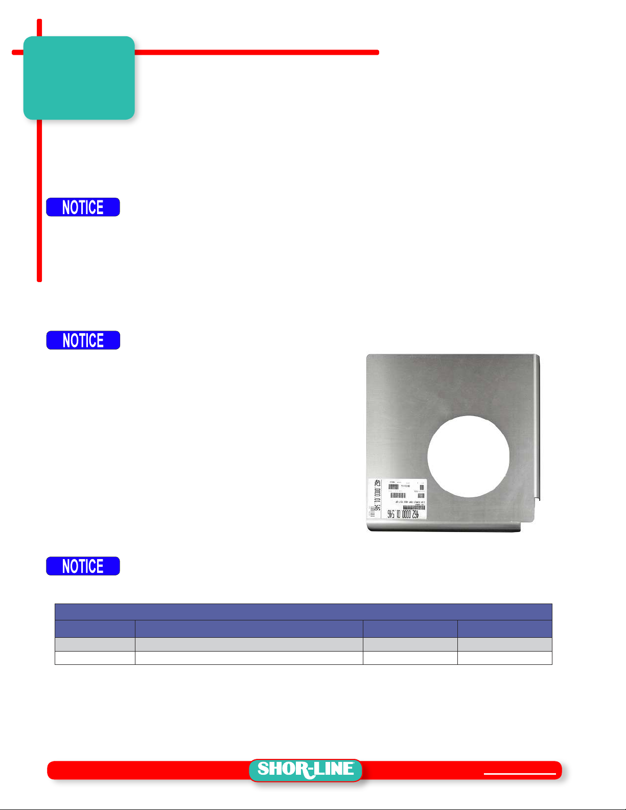
Hole Template..................................................................................................................... 3
Parts List............................................................................................................................. 4
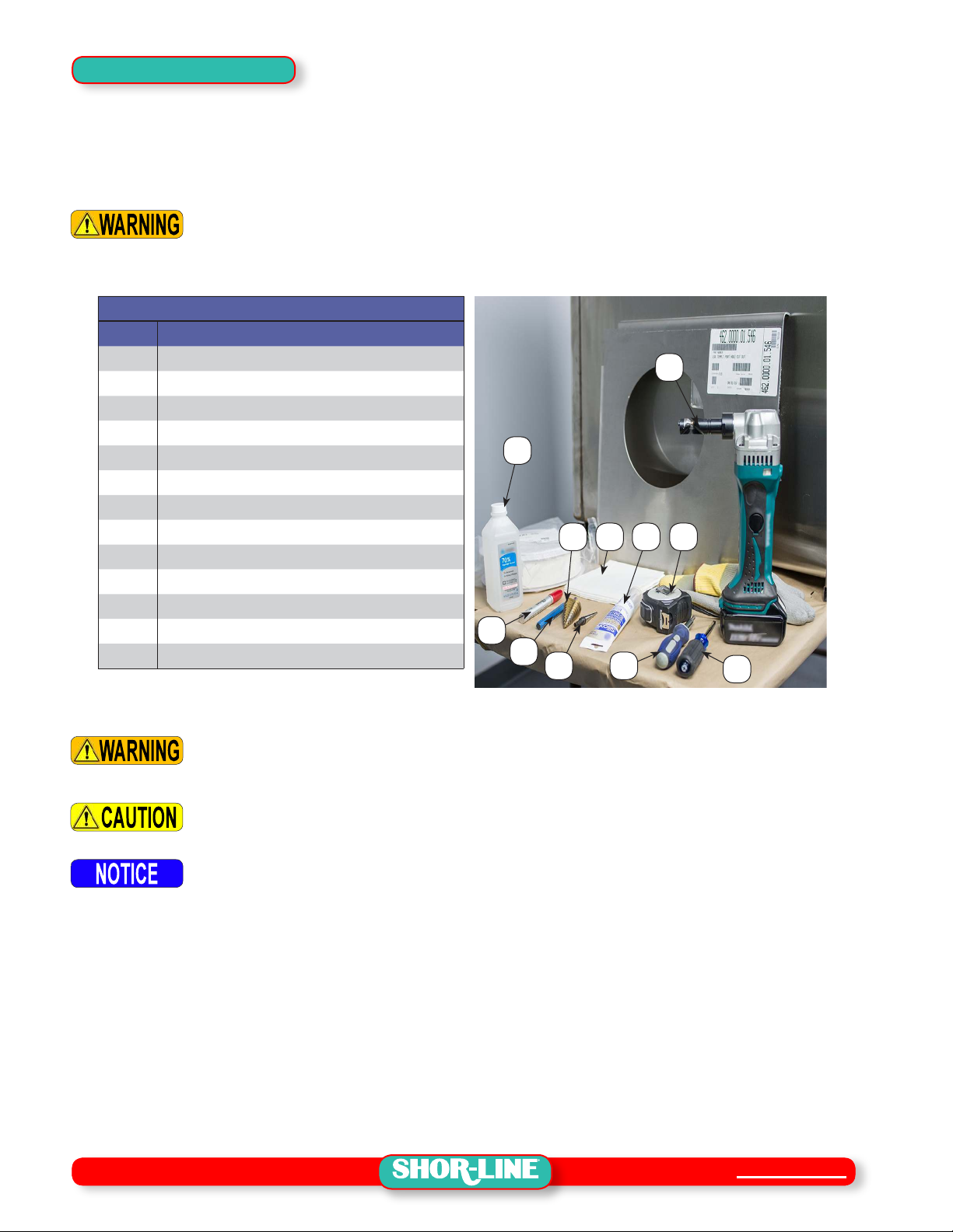
Tools And Equipment.......................................................................................................... 5
SECTION TWO, ASSEMBLY PROCEDURES
Assembly Procedures..................................................................................6
Cage Preparation ............................................................................................................... 6
Portal Location.............................................................................................................. 6
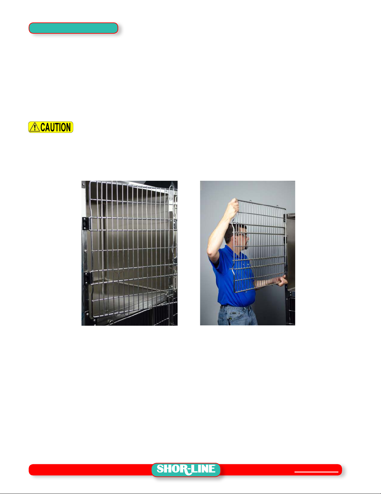
Cage Door Removal ..................................................................................................... 7
Portal Hole.......................................................................................................................... 8
Template ....................................................................................................................... 8
Mark/Punch Starter Hole .............................................................................................. 9
Drill Starter Hole ......................................................................................................... 10
Portal Hole Cut ........................................................................................................... 10
Portal Installation .............................................................................................................. 12
Spacer Installation ...................................................................................................... 12
Flange Components Installation ................................................................................. 13
Door Installation.......................................................................................................... 14
SECTION THREE, OPERATION & MAINTENANCE
Portal Use And Care ..................................................................................16
Door Operation ................................................................................................................. 16
Opening and Closing the Portal Door ......................................................................... 16
General Maintenance & Care ........................................................................................... 17
Maintenance Recommendations ................................................................................ 17
Care Recommendations ............................................................................................ 17
SECTION FOUR, TERMS & CONDITIONS
Terms And Conditions................................................................................18
Damaged Freight Procedures .......................................................................................... 18
Limited Warranty ......................................................................................20
Limitation Of Liability................................................................................................... 20
Contact Information ...................................................................................21
CONTENTS

Shor-Line.com
1
GENERAL INFORMATION
General information
Refer to the Guide, images and content to assist with the installation of the product.
Throughout the Guide, safety notices provide help for a successful installation.
SAFETY FIRST!
Shor-Line uses the following symbols and signal words to identify potential hazards or
unsafe practices:
Safety Alert Symbol
Indicates a potential personal injury hazard exists. It is important to heed any safety
warning information associated with this alert symbol.
Signal Words for Hazard Alerting Safety Messages
Indicates a hazardous situation which, if not avoided, WILL result in serious injury
or death.
Indicates a hazardous situation which, if not avoided, COULD result in serious injury
or death.
Indicates a hazardous situation which, if not avoided, COULD result in minor or
moderate injury.
Important Information Symbol
Indicates information considered important but not directly hazard related.
Personal Protective Equipment (PPE)
PPE refers to protective clothing or other equipment designed to protect against injury. It
is the responsibility of the client/installer to ensure all local and federal codes are adhered
to during the installation and assembly of this product. Included is a list of PPE items
suggested, but not limited to, protective equipment to help complete the installation safely.
• Eye protection • Gloves
• Metatarsal, foot protection • Back Support Brace
• Ear protection
SHOR-LINE makes no guarantee, implied or otherwise, that the information included in
this Guide will be complete or failsafe, or that the information will prevent an injury from
occurring. Standard measures described may not reect the full extent of all steps that may
need to be taken in any given emergency instance.
California Proposition 65 Warning
This product can expose you to chemicals
including chromium, which are known to the
state of California to cause cancer. For more
information go to: www.P65Warnings.ca.gov
SAFETY

2
Shor-Line.com
Safety Warnings Included In This Guide
READ THIS GUIDE COMPLETELY BEFORE INSTALLATION AND USE AND
THOROUGHLY UNDERSTAND AND FOLLOW ALL SAFETY INSTRUCTIONS.
DO NOT use a plasma cutter to cut the Portal hole. Plasma cutters can create excessive
heat that can result in severe burns or re which will cause SERIOUS PERSONAL
INJURY OR DEATH.
PRIOR TO DRILLING OR CUTTING A CAGE PANEL, ALWAYS INSPECT the space
between the cage panels to be sure there are no electrical wires or other obstructions
present. Cutting into live wires or other obstructions can result in electrical shock
which will cause SERIOUS PERSONAL INJURY OR DEATH or property damage.
Installation of the Portal MUST BE COMPLETED BY A QUALIFIED INSTALLER familiar
with sheet metal manipulation/modications. Cutting or drilling into metal cages can
produce sharp or jagged edges which could cause serious lacerations which, if not
avoided, could result in SERIOUS INJURY OR DEATH.
Stay clear of and DO NOT TOUCH exposed cut steel. Cutting or drilling into metal cages
can produce sharp or jagged edges which could cause serious lacerations which, if not
avoided, could result in SERIOUS INJURY OR DEATH.
Stainless steel cages are heavy. Enlist help and USE SAFE LIFTING PRACTICES when
removing any cages from or placing cages back into the cage bank to avoid risk of
SERIOUS INJURY OR DEATH.
WEAR PERSONAL PROTECTIVE EQUIPMENT, such as, but not limited to, eye
protection, ear protection, and gloves during installation. Failure to do so could result
in SERIOUS INJURY OR DEATH.
This product is intended to be used for animals only. Do not use for anything other than
the intended purpose.
Be sure to secure long hair or loose tting clothing during installation. Long hair or
loose tting clothing can become ensnared on exposed (cut) stainless steel edges and
cutting tools, and if not avoided, could result in minor or moderate injury.
Keep hands clear of possible pinch areas when moving parts, which if not avoided,
could result in minor to moderate injury.
SHOR-LINE is not responsible for replacing mis-cut or damaged cages.
During cleaning and maintenance, DO NOT pull the Portal Door away from the cage
wall. Injury or damage to property could occur.
SAFETY

Shor-Line.com
3
SECTION ONE, PRE-ASSEMBLY
Shipment Inventory And Inspection
Shipment Inventory
At arrival, unpack and inspect the shipment to ensure it is complete and free of damages
that may have occurred during shipping. Compare the packing list with the shipment to
ensure all parts/components have been received in good condition. See FIGURES 1.1-1.2
Avoid using razor blade or cutting devices, product surfaces scratch easily.
Shipment Inspection
While verifying the shipment contents, take a moment to inspect each component for
damage. This should be done before the shipment is signed received and accepted. If
damaged components are apparent, follow the claim procedures set forth by the carrier.
Damage Reporting
Follow the instructions within Shor-Line’s Damage and Freight Procedures. Contact Shor-
Line (800.444.1579) immediately to expedite the process.
After fteen (15) calendar days of receipt of merchandise, this policy becomes void.
Hole Template
The SHOR-LINE Portal comes complete with the
portal components, spacer, and hardware required to
complete the installation. The two cages that are to
be linked, using the Portal, will have to be modied to
receive the Portal.
The Portal does NOT include the hole Template
unless it was ordered at the time of purchase.
A .125" thick aluminum plate hole Template is
available and can be ordered to assist locating the
proposed holes in each cage. See FIGURE 1.1
The Template is useful and durable; the same
Template can be reused for each Portal installation.
It is important to locate the proposed holes perfectly aligned to each other in each
cage. The Template insures consistent location on both the left and right cages.
SHOR-LINE is not responsible for replacing mis-cut or damaged cages.
PORTAL TEMPLATES
PART # DESCRIPTION OPENING HOLE CENTER
300.2229.00 Kat Portal Hole Template - Aluminum Plate 8.5" Diameter 8-5/16" Oset (Both)
300.2334.00 Puppy Portal Hole Template - Aluminum Plate 12.5" Diameter 8-5/16" Oset (Both)
FIGURE 1.1 - Template (Kat Portal Shown)
SECTION
ONE

4
Shor-Line.com
Parts List
FIGURE 1.2 - Portal Assembly (Kat Portal Shown)
01
03
09
04
02
06
08
10
05
07
PORTAL ASSEMBLY CONTENTS
ITEM PART # DESCRIPTION QTY □
902.0000.30 Kat Portal - Standard Model (See Contents Below)
01 • Portal - Female Flange (Marked "B") 1□
02 • Portal - Male Flange (Marked "A") 1□
03 • Portal - Door Panel 1 □
04 • 181.9020.06 • Kat Portal - Standard Model, 2" Wide Spacer (Styles Vary) 1□
• 802.0000.25 Hardware Kit (See Contents Below)
05 • #8-16x1 Pan Hd Phillips, Hi-Lo, Stainless Steel 2□
06 • #10-32x1.5 Truss Hd Phillips, Stainless Steel 2□
07 • #10-0.668x0.203 Flat Washer, Stainless Steel 2□
08 • .250x0.682x0.328 Wave Washer, Stainless Steel 1□
09 • Quick Release Pin Assembly 1□
10 • Short Nylon Stando Spacer (Kat Portal) 2□
NOT SHOWN • Long Nylon Stando Spacer (Puppy Portal) 2□
PORTAL CONFIGURATIONS
PART # DESCRIPTION OPENING APPLICATION
902.0000.30 Kat Portal - Standard Model (See FIGURE 1.2) 6.25 wide x 7.5" tall Standard 2" Gap Cage
• 181.9020.06 • Kat Portal, 2" Wide Spacer (Styles Vary)
902.0000.31 Kat Portal - Narrow Model 6.25 wide x 7.5" tall Cat Condo 1.5" Gap
• Spacer Not Required
902.0000.32 Kat Portal - Wide Model (Custom Depth Portal) 6.25 wide x 7.5" tall Wide 3" Gap Cage
• Spacer Customer Provided
902.0000.33 Puppy Portal - Standard Model 10.25 wide x 11.5" tall Standard 2" Gap Cage
• 181.9020.10 • Puppy Portal Spacer, 2" Wide (Styles Vary)
902.0000.34 Puppy Portal - Wide Model 10.25 wide x 11.5" tall Wide 3" Gap Cage
• Spacer Customer Provided
SECTION ONE

Shor-Line.com
5
Tools And Equipment
Tools and equipment required to complete the installation can vary depending on the task at
hand and type of construction method employed. Below is a list of tools and equipment used
in the installation procedures outlined in this Guide. Techniques may vary.
Installation of the Portal MUST BE COMPLETED BY A QUALIFIED INSTALLER familiar
with sheet metal manipulation/modications. Cutting or drilling into metal cages can
produce sharp or jagged edges which could cause serious lacerations which, if not
avoided, could result in SERIOUS INJURY OR DEATH.
TOOLS LIST
ITEM DESCRIPTION
01 MEASURING TAPE
02 PAINT PEN OR MARKER
03 CLEAN/SOFT TOWELS
04 RUBBING ALCOHOL
05 HAMMER (NOT SHOWN)
06 PUNCH
07 DRILL, STARTER DRILL BIT (NOT SHOWN)
08 STEP HOLE DRILL BIT (UP TO 1/2")
09 STEP HOLE DRILL BIT (UP TO 1-1/2")
10 SHEER NIBBLER
11 SILICONE (CLEAR)
12 PHILLIPS HEAD SCREWDRIVER (#2)
13 PHILLIPS HEAD SCREWDRIVER (#3)
01
1103
10
04
02
06 08
09
13 12
WEAR PERSONAL PROTECTIVE EQUIPMENT, such as, but not limited to, eye
protection, ear protection, and gloves during installation. Failure to do so could result
in SERIOUS INJURY OR DEATH.
Be sure to secure long hair or loose tting clothing during installation. Long hair or
loose tting clothing can become ensnared on exposed (cut) stainless steel edges and
cutting tools, and if not avoided, could result in minor or moderate injury.
Ensure the tools are properly maintained. Drill bits and cutting heads should be in
good order. Use drilling oil as required.
SECTION ONE

6
Shor-Line.com
SECTION TWO, ASSEMBLY PROCEDURES
Assembly Procedures
Cage Preparation
Portal Location
The following instructions include the steps and precautions to install one Portal between
two cages that are a part of a cage bank. Repeat the procedures for each Portal installation.
Installation of the Portal MUST BE COMPLETED BY A QUALIFIED INSTALLER familiar
with sheet metal manipulation/modications. Cutting or drilling into metal cages can
produce sharp or jagged edges which could cause serious lacerations which, if not
avoided, could result in SERIOUS INJURY OR DEATH.
The Template can be used to mark the Portal hole location from the inside of the cage
and can also be used to locate the holes from the outside of the cage. Depending on the
size of the proposed cages, it may be determined that hole placement and cutting may
be easier from the outside of the cage. The Trim Plates (#3 Phillips Head Screwdriver)
will have to be removed and the cages will have to be removed from the bank for this
type of installation.
Stainless steel cages are heavy. Enlist help and USE SAFE LIFTING PRACTICES when
removing any cages from or placing cages back into the cage bank to avoid risk of
SERIOUS INJURY OR DEATH.
Any cages removed during the hole cutting process will have to be reinstalled in the cage
bank before continuing with the Portal installation.
For the purpose of these instructions each cage will have a unique identier, the cage on the
right is "CAGE ONE" and the cage on the left is considered "CAGE TWO". See FIGURE 2.1
FIGURE 2.1 - Cage Identication (Example)
CAGE
ONE
CAGE
TWO
SECTION
TWO

Shor-Line.com
7
Cage Door Removal
Door hinges may vary depending on the release model of the cages. Type III cages
are used for this procedure. Contact SHOR-LINE for door removal procedures for older
model cages.
STEP 1: Ensure both proposed cages are cleared of animals, bedding, and are
thoroughly clean.
STEP 2: Remove the door from the Cage.
A: Unlatch and swing door to the open position (90 degrees). See FIGURE 2.2
Keep hands clear of possible pinch areas when moving parts, which if not avoided,
could result in minor to moderate injury.
B: Lift the door upward and slide the door from the hinges. Set away from the work
area. See FIGURE 2.3
STEP 3: Repeat the door removal steps for each Cage to be tted with a Portal.
FIGURE 2.3 - Cage Door Removal
FIGURE 2.2 - Cage Door Removal
SECTION TWO

8
Shor-Line.com
Portal Hole
Template
The portal holes can be cut with the cages located in a bank or as a stand-alone cage. For
the purpose of this Guide, instruction included will describe the steps required to cut the
portal holes with the cages located within a bank of cages.
Installation of the Portal MUST BE COMPLETED BY A QUALIFIED INSTALLER familiar
with sheet metal manipulation/modications. Cutting or drilling into metal cages can
produce sharp or jagged edges which could cause serious lacerations which, if not
avoided, could result in SERIOUS INJURY OR DEATH.
Allowing the cutting tool to run o-line will
cause irreparable damage to the cage. SHOR-
LINE is not responsible for replacing mis-cut or
damaged cages.
The Template and a marker will be used to located
a hole in the side walls of the two cages that are to
receive the Portal.
STEP 4: Gently move the Template into CAGE ONE,
resting the bent aluminum (ange) against
the side and back panels. See FIGURE 2.4
STEP 5: Move the Template down and rest against the bottom and back panels. The
radius of the anges match the radius of the cage for a snug t.
STEP 6: Once the Template is in place, mark the
side panel using the Template as a guide
for the hole location. See FIGURE 2.5
STEP 7: Remove the template, careful not to
smudge the hole marking or scratch the
cage surface.
STEP 8: The Template will have to be rotated to
rest in CAGE TWO. Insert the Template
and mark the hole location following the
same steps used to locate the hole for
CAGE ONE.
FIGURE 2.4 - Template
FIGURE 2.5 - Template
SECTION TWO

Shor-Line.com
9
Mark/Punch Starter Hole
A hammer, punch, drill, step hole drill bits, and cleaning
supplies will be used to create a starter hole. This hole
will be the start point for the Nibbler cutting tool, the
hole must be large enough to t the cutting head of the
Nibbler to begin the cut.
Location of the hole will vary depending on model/size
of the Nibbler used to cut the portal hole.
STEP 1: Dry run: Hold the Nibbler along the cutting
line to ensure there is enough clearance to
fully rotate the cutting tool without making
contact with the back and bottom panels.
See FIGURE 2.6
STEP 2: Establish a comfortable starting point,
where the Nibbler will be able to rotate
around the hole clearing the back and
bottom panels.
STEP 3: Mark a punch location within the portal
hole. The mark should be inside the
circle and oset the minimum distance
for the cutting hole to be drilled. 3/4" for
these procedures. See FIGURE 2.7
STEP 4: Use the hammer to strike the punch,
locating an indention in the panel. This
indention provides a starting point for the
drill bit. See FIGURE 2.8 and 2.9
FIGURE 2.9 - Punch IndentionFIGURE 2.8 - Punch Indention
FIGURE 2.6 - Test Clearance
FIGURE 2.7 - Punch Location
SECTION TWO

10
Shor-Line.com
Drill Starter Hole
A starter hole will have to be drilled in order to insert (start) the Nibbler. Take care to ensure
the starter hole does not encroach or expand past the portal hole outline.
PRIOR TO DRILLING OR CUTTING A CAGE PANEL, ALWAYS INSPECT the space
between the cage panels to be sure there are no electrical wires or other obstructions
present. Cutting into live wires or other obstructions can result in electrical shock
which will cause SERIOUS PERSONAL INJURY OR DEATH or property damage.
The punched indention helps center the drill bit in place. Care should be taken when
drilling holes in steel, as the drill bit can release from the punched indention and
scratch the cage surface.
STEP 1: Use a power Drill and a 1/4" Drill Bit to start a hole at a size that will accept a Step
Drill Bit. See FIGURE 2.10
FIGURE 2.11 - Step DrillFIGURE 2.10 - Starter Hole
STEP 2: Use a power Drill and Step Drill Bit to increase the hole to a size that will accept
the cutting head (Up to 7/8"). See FIGURE 2.11
STEP 3: Remove metal shavings and clean the cage of debris.
Portal Hole Cut
DO NOT use a plasma cutter to cut the Portal hole. Plasma cutters can create excessive
heat that can result in severe burns or re which will cause SERIOUS PERSONAL
INJURY OR DEATH.
PRIOR TO DRILLING OR CUTTING A CAGE PANEL, ALWAYS INSPECT the space
between the cage panels to be sure there are no electrical wires or other obstructions
present. Cutting into live wires or other obstructions can result in electrical shock
which will cause SERIOUS PERSONAL INJURY OR DEATH or property damage.
Installation of the Portal MUST BE COMPLETED BY A QUALIFIED INSTALLER familiar
with sheet metal manipulation/modications. Cutting or drilling into metal cages can
produce sharp or jagged edges which could cause serious lacerations which, if not
avoided, could result in SERIOUS INJURY OR DEATH.
SECTION TWO

Shor-Line.com
11
There are several techniques (tools) that can be used
to cut a hole in stainless steel. For the purpose of this
Guide, instruction included will describe the steps
required to cut the portal holes with a Nibbler using a
11/16" cutting head.
The cutting head will have to be locked into place,
perpendicular to the handle of the Nibbler. "Free"
and straight cutting positions could cause clearance
issues due to the location of the hole and its proximity
to the back and bottom panels of the cage. See
FIGURE 2.12
STEP 1: Insert the cutting head into the hole and locate a starting point to begin the cut.
See FIGURE 2.13
FIGURE 2.13 - Start Cut FIGURE 2.14 - Rotate Nibbler
STOP cutting, realign at any point during the cut if the cutting head strays from the hole
guide line. Mis-cuts can damage the cage and aect the seal of the Portal.
STEP 2: Rotate the Nibbler as it cuts the steel, following the hole guide line.
See FIGURE 2.13 to 2.16
FIGURE 2.15 - Rotate Nibbler FIGURE 2.16 - Rotate Nibbler
STEP 3: Bend, le any edge surfaces protruding from the panel
wall that could aect the seal. See FIGURE 2.17
STEP 4: Remove metal shavings and clean the cage of debris.
FIGURE 2.12 - Nibbler Rotation
PIVOT
*
BIT CUT
DIRECTION
FIGURE 2.17 - Hole
SECTION TWO

12
Shor-Line.com
Portal Installation
Spacer Installation
Stage the Flange A in Cage TWO and the Flange B in Cage ONE. To discern between
components, the Flange A has mounting holes on the trim face. See FIGURES 2.18
and 2.19
FIGURE 2.18 - Flange A FIGURE 2.19 - Flange B
The Flange components will be inserted following the Spacer installation and should be
staged in each Cage, within reach. See FIGURE 2.20
FIGURE 2.20 - Flange Staging
CAGE
ONE
CAGE
TWO
FIGURE 2.21 - Spacer
The Spacer provides support between the Cage walls to help prevent wall panel movement.
The diameter of the Spacer is larger than the Portal hole. The Spacer has a split seam
which, when the two ends of the ring are collapsed can rest on each other reducing the
diameter, enabling the Spacer to be inserted into the hole. See FIGURE 2.21
STEP 1: Collapse one end of the Spacer ring inside the other. See FIGURE 2.21
STEP 2: Insert the Spacer ring in-between the two cages. HOLD IN PLACE. See
FIGURE 2.22 & 2.23
FIGURE 2.22 - Spacer Insertion FIGURE 2.23 - Spacer Installed
SECTION TWO

Shor-Line.com
13
Flange Components Installation
STEP 1: Add a 1/4" continuous bead of clear silicone
to the inside of each Flange. Read and
follow the manufacturers instructions for
silicone application. See FIGURE 2.24
STEP 2: Carefully rotate the anges to ensure the
attachment holes are parallel to the cage
oor. See FIGURE 2.25
STEP 3: Insert the Female Flange Component
through the hole/Spacer. The arrow and
notch on the Flange should point upward.
See FIGURE 2.26
STEP 4: Insert the Male Flange Component inside the Female Flange Component. The
arrow, SHOR-LINE logo and notch on the Flange should be in the upward
position. See FIGURE 2.27
FIGURE 2.25 - Connection
EQUAL DISTANCE
EQUAL DISTANCE
Carefully rotate the anges to
ensure the attachment holes
are parallel to the cage oor.
FIGURE 2.26 - Female Flange FIGURE 2.27 - Male Flange
STEP 5: Use two #8-16X1 PAN HD phillips screws to secure the two anges together. The
screws thread into the plastic ange. See FIGURE 2.28
STEP 6: Wipe clean any Silicone that has oozed out between the Flange and Cage wall.
See FIGURE 2.29
Do NOT over-tighten the screws, damage to the components could occur.
FIGURE 2.28 - Secure Flanges FIGURE 2.29 - Clean Portal
FIGURE 2.24 - Silicone Application
SECTION TWO

14
Shor-Line.com
Door Installation
The Portal Door is secured with one screw on the hinge side, and one screw on the door
stop side. The Door is in the closed position when the paw is facing down, inversely, the paw
is facing up when the Door is in the open position. See FIGURE 2.30 and FIGURE 2.31
FIGURE 2.30 - Door Closed Position FIGURE 2.31 - Door Open Position
See FIGURE 1.2 to help identify each piece of hardware used for the door installation.
It is important to install all hardware in the correct order for the Door to operate
correctly. Do NOT over-tighten screws, damage to the components could occur. Refer
to the parts list (FIGURE 1.2) for hardware assembly order. The short Nylon Spacers are
used for the Kat Portal and the long Nylon Spacers are used for the Puppy Portal.
STEP 1: Use one (1) of the Phillips screws, one (1)
Flat Washer, the Wave Washer, and one
(1) Nylon Stando Spacer to secure the
hinge side of Door. See FIGURE 2.32
STEP 2: Tighten the Hinge Screw just tight
enough to provide tension on the Door.
Rotate the Door to the open position
to ensure free movement, yet the Door
Hinge Screw should be tight enough to
hold the door in any position. FIGURE 2.32 - Door Hinge Assembly
SECTION TWO

Shor-Line.com
15
STEP 3: Use one (1) of the Phillips screws, one
(1) Flat Washer, Quick Release Pin
Assembly, and one (1) Nylon Stando
Spacer to secure the door stop side of
Door. See FIGURE 2.33
The screw is threaded into the Male
Flange and does NOT go through the
Door.
The short Nylon Spacers are used for the
Kat Portal and the long Nylon Spacers are
used for the Puppy Portals.
Refer to the parts list (FIGURE 1.2) for hardware
assembly order.
STEP 4: With the Door in the closed position,
paw down, the Quick Release Pin can
be inserted into the hole to secure the
Door closed. See FIGURE 2.34
STEP 5: Thoroughly clean both Cages and the Portal to ensure the removal of all
chemicals and metal shavings before allowing the Cages to become occupied.
STEP 6: Reattach the Cage Doors.
FIGURE 2.34 - Secure Door
FIGURE 2.33 - Quick Release Assembly
SECTION TWO

16
Shor-Line.com
SECTION THREE, OPERATION & MAINTENANCE
Portal Use And Care
Door Operation
Opening and Closing the Portal Door
Once the Portal is installed, the door can be used to control access to one cage or the other
by rotating the door to the closed or open position, as desired. The Door is in the closed
position when the paw is facing down. Inversely the paw is facing up when the Door is in the
open position. See FIGURE 3.1 and FIGURE 3.2
FIGURE 3.1 - Door Closed Position FIGURE 3.2 - Door Open Position
PAW UP
OPEN
PAW DOWN
CLOSED
A pin is provided to lock the door in the closed position. Remove the pin from the stowed
position, close the door and insert the pin through the Lock Hole. See FIGURE 3.3
FIGURE 3.3 - Door Lock
LOCK HOLE
LOCK PIN
THREE
SECTION

Shor-Line.com
17
General Maintenance & Care
Maintenance Recommendations
Routine maintenance will extend the quality and life of Shor-Line products.
It is the owners responsibility to set-up scheduled maintenance programs, depending on
use of the equipment. Scheduled preventive maintenance should include, but not limited
to daily or weekly inspections and maintenance of products to prolong its longevity and
to help maintain proper product functions.
• Follow manufacturers cleaning and maintenance recommendations outlined in product literature
provided for components not included in these recommendations. Congurations/component parts
may vary.
• Check alignment of operable panels, doors and components to ensure operation is free of
obstructions. Adjust as required.
• Check any battery compartments to ensure the batteries are not failing, corroding the
contacts or damaging the equipment. A pencil eraser can be used to clean electrical contacts
in battery compartments.
• Check any wiring for kinks or exposed inner wiring. If damage exist, stop equipment use and
contact Shor-Line Technical Services for direction.
• Check any hydraulic lift components for leaking uid. If uid is present, stop equipment use and
contact Shor-Line Technical Services for direction. Do NOT attempt to repair hydraulic leaks.
Care Recommendations
Routine product care will extend the quality and life of Shor-Line products and aids in
protecting animals from transmittable diseases and infections.
It is the owners responsibility to set-up scheduled cleaning programs, depending on
use of the equipment. Scheduled preventive cleaning should include, but not limited to
daily or weekly inspections and cleaning of products to prolong its longevity and to help
maintain nishes.
Safe Cleaning Practices
• Use the mildest cleaning procedure that will complete the job eectively. Ordinary waste deposits
and uids can usually be removed with soap and water, using a soft cloth or sponge. Rinse
thoroughly with clear water and dry completely with a soft cloth to discourage hard-water spotting.
• Minor scale build up and some hard water spotting can be removed by washing with a vinegar
diluted mixture followed by a clear water rinse and thorough drying.
• Bleach, deodorizing agents, disinfectants, and sanitizers can corrode stainless steel, thoroughly
rinse all surfaces treated with these chemicals with a clear water rinse and dry with a soft cloth.
• If scrubbing is required, use only polymer or nylon ber products made for use with polymer or
nylon materials.
• Always rinse with clear water and dry of all surfaces treated with cleaning, sterilization solutions.
Unsafe Cleaning Practices (NOT Recommended)
• Do NOT use a dry cloth or wipe clear polymer surfaces which can scratch if dust/dirt is wiped with
the hand or dry cloth.
• Polymer materials can discolor if exposed to sunlight, ultraviolet rays. Avoid direct sun exposure.
• Do NOT use ammonia or bleaches to clean polymer surfaces.
• Do NOT allow uids to accumulate, puddle without removing and completely drying the
surfaces and components. Standing water/uids are a hazard and can cause damage to
component materials.
• Do NOT use scouring powders that will scratch polymer nishes.
Steel wool or steel brushes should never be used to clean stainless steel or polymer
surfaces, avoid abrasive cleaning techniques/supplies.
SECTION THREE
Table of contents
Other SHOR-LINE Pet Care Product manuals
Popular Pet Care Product manuals by other brands

DELTA-SPORT
DELTA-SPORT Zoofari HM-6879 Instructions for use

Innotek
Innotek Spray Commander Instruction guide

PawHut
PawHut D51-153 manual

Solvit
Solvit Strolling Kit for Houndabout II Care/use guide

Endura Flap
Endura Flap Thermo Sash IIIe Installation instructions manual

SURE petcare
SURE petcare Animo quick start guide