Shure SM-02 User manual
Other Shure Microphone System manuals
Shure
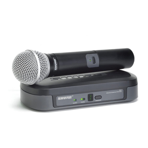
Shure Performance Gear User manual
Shure
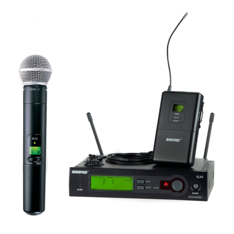
Shure SLX Wireless System User manual
Shure
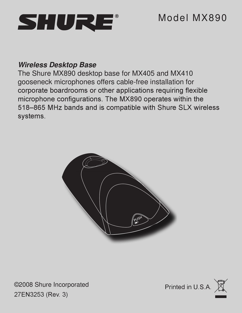
Shure MX890 User manual
Shure
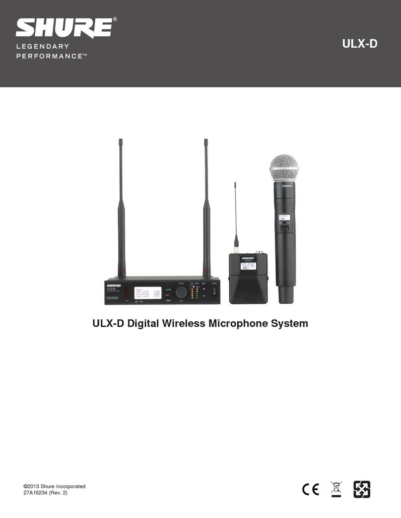
Shure ULX-D Programming manual
Shure
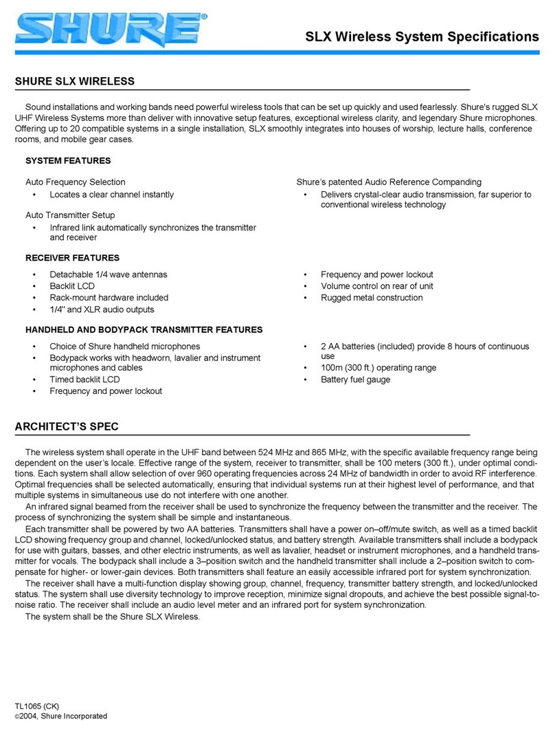
Shure SLX Wireless System User manual

Shure
Shure UA844 User manual

Shure
Shure SLX Wireless System User manual
Shure
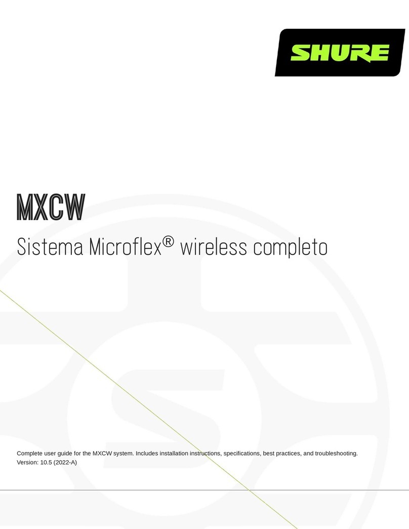
Shure Sistema Microflex MXCW User manual

Shure
Shure AMS4000 User guide

Shure
Shure PA821A User manual
Shure
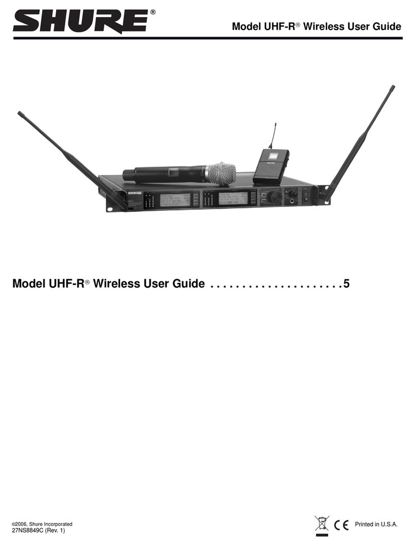
Shure UHF-R Wireless User manual
Shure
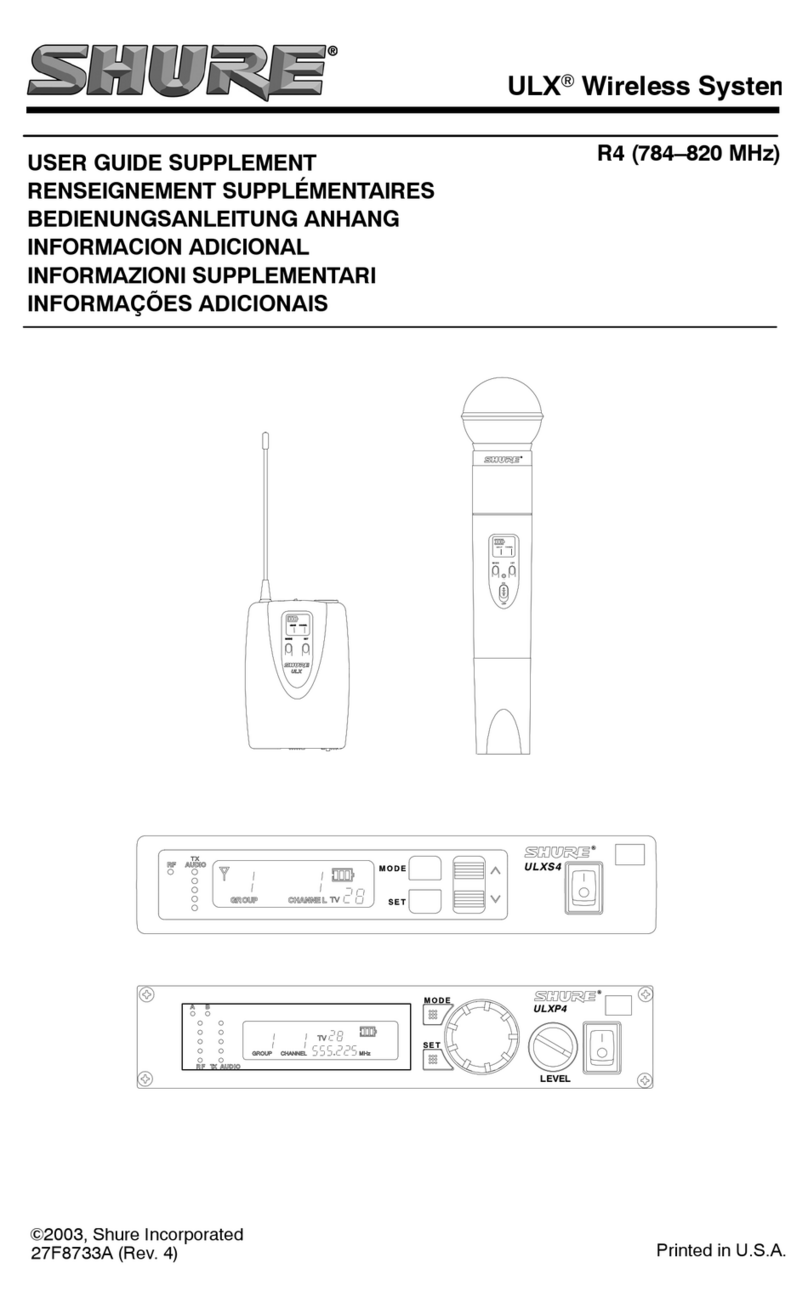
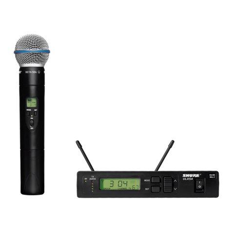
Shure ULXS4 User manual
Shure
Shure KSM11 User manual
Shure
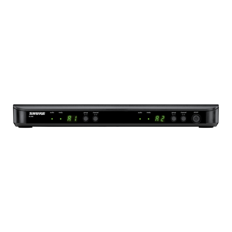
Shure BLX88 User manual
Shure
Shure QLX-D User manual
Shure
Shure THE TWIN PRO 27C8642 User manual
Shure
Shure BLX Wireless System User manual
Shure
Shure R175 Technical manual
Shure
Shure A412B User manual
Shure
Shure UHF-R Wireless User manual
Popular Microphone System manuals by other brands

Sennheiser
Sennheiser Evolution Wireless Digital EW-DX EM 2 quick guide

Alpha Technologies
Alpha Technologies RBMS Installation & operation manual

SWIT Electronics Co.,LTD.
SWIT Electronics Co.,LTD. CW-S150 user manual

Panasonic
Panasonic SHFX70 - DVD HOME THEATER WIRELESS SYSTEM operating instructions

Pyle
Pyle PDWM5000 user manual

Airspan
Airspan AS4000 Installation and commissioning
