manuals.online logo
Brands
  1. Home
  2. •
  3. Brands
  4. •
  5. Shuttle
  6. •
  7. Motherboard
  8. •
  9. Shuttle HOT-649A User manual

Shuttle HOT-649A User manual

HOT- 649A
HOT-649AInstallationguide
(Completemanualanddriversonthe
Spacewalker-CDROM)
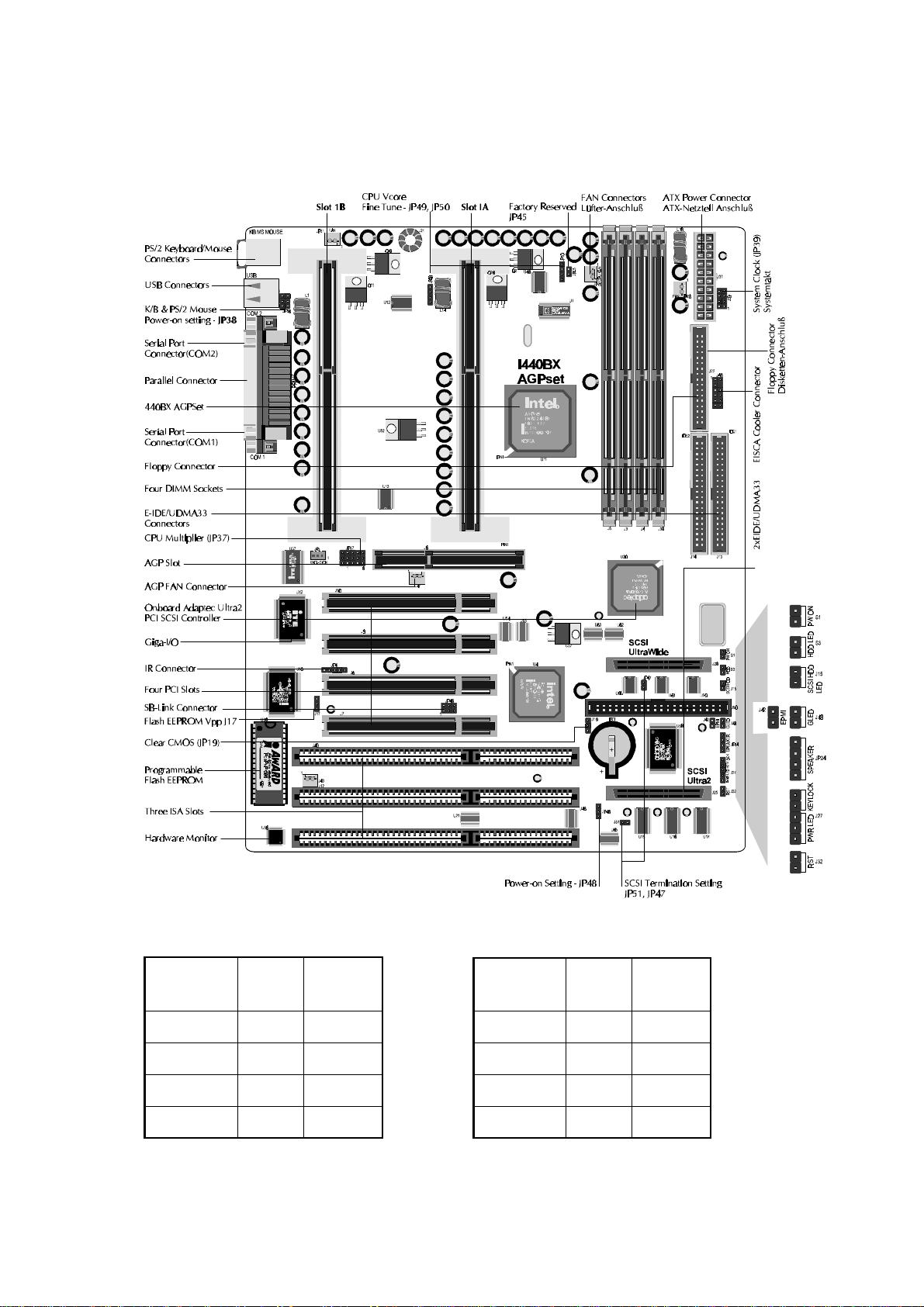
1) HOT-649Amainboardnotonlysupportsingleor
dualIntelPentium II processor withsystembus
frequenciesof100MHzor66MHzbutalsoprovide
AdaptecAIC7890&ACI386080 MB/sUltra2
Wide SCSI chips. The new Ultra SCSI is
deliveringfasterbusspeedsandgreater
connectivitythat can balance theperformance
andefficiency between fast system cores and
peripherals.
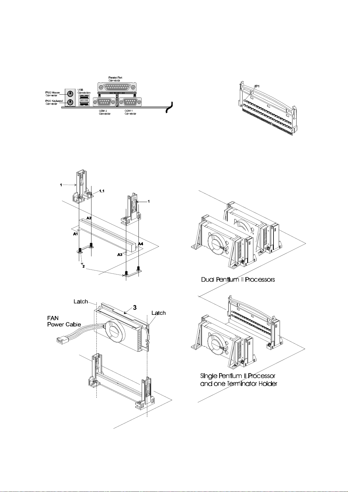
2a)Processor Installation:
InserttwoURM(Universal Retention Mechanism)
(1)onoppositeside of Slot 1. FixURM(1)by
insertingAttachMounts(2) up throughholes
(A1...A4)inthebottomofthe mainboard, and
screwthefourcaptive nuts(1.1).
Holdtheprocessor(3) so that the Heatsinkis
facingtowardtheDIMM sockets on the
mainboard.
Slidetheprocessor into the URM.Pushthe
processordownfirmly,with even pressure on
both sides of the top, until it is seated.
2b)DualorSingleProcessor Installation:
HOT-649AsupportDualor Single Pentium II
processor, when single processor is used, a
terminatorholder is required.
3) CPUHostClock66~150MHz and
CPUClock Ratio 2x~ 5x soft-configure in BIOS
"ChipsetFeaturesSetup"
4) CPUHostClockhard-configureaccordingtothe
table2andCPU Clock Ratio hard-configure
accordingtothetable 3.
Jumperswillbe shown graphically suchasfollow:
Jumper open:
Jumper close:
5) Memory-Configuration:the168pinsocketscan
befilledwith normal SDRAM orPC/100SDRAM
modulesin sizes of 8,16, 32, 64,128or 256MB.
6) Figure1 shows the peripheraldevice
connectorsonthebackpanel.
7) Power on the computer and press <DEL>
immediatelywillallowyoutoenter BIOS setup
program.
HOT-649AKurzanleitung
(AusführlichesHandbuch auf derSpacewalker-
CDROM)
All other brand and product names within this guide are the
propertyof their respectiveowners. Shuttle assumesno re-
sponsibility for any errors or omissions. Nor does Shuttle
makeany commitmenttoupdate information,with orwithout
priornotification.
AlleaufdiesemBlattaufgeführten Marken-undProduktnamen
sindeingetrageneWaren-oder Produktzeichenderjeweiligen
Besitzer. Druckfehler, Irrtümer, Innovationen und technische
Änderungenvorbehalten.
1) DasHOT-649AMainboardunterstützt einen oder
zweiPentium-II-Prozessorenfüreinem Systemtakt
von66oder100MHz.Darüberhinaus verfügtdas
BoardübereinenAdaptecSCSI-Kontrollermitden
ChipsAIC7890& AIC 3860 für Ultra2-Wide(max.
80MB/s),Ultra-WideundUltra. Der neue Ultra2-
Wide-Standardermöglichteinenbesonders hohen
DatendruchsatzundbessereConnectivity,sodaß
CPU/SpeicherundleistungsfähigePeripherie
schnellerundeffektiverzusammenarbeiten können.
2a)InstallationdesProzessors:
AnbeidenEndendesSlot1wirdjeweilsein
Universal-CPU-Halter(1)gesteckt.Befestigungs
bügel(2)von unten durch dieBohrungenim
Mainboard(A1...A4)führenundHalterdurchdie
Schraubmuttern(1.1)fixieren.
DieKühlrippendesProzessor (3) zeigen in
RichtungderDIMM-SockeldesMainboards.Den
ProzessorläßtmanindieHalterung gleiten. Dann
andenoberenSeitenanfassenundfest
hineindrücken,bisereinrastet.
2b)Betriebmit einem oder zweiProzessoren:
HOT-649Akannwahlweisemit einem oder zwei
Prozessorenbetriebenwerden.Fallsnurein
Prozessorbenutztwird, dann muß indenleeren
CPU-SockeleinTerminatorgestecktwerden.
3) SoftwaremäßigeEinstellungvonSystemtakt (66 bis
150MHz)und CPU-Taktverhältnis (2x bis5x)im
Bios-Setupunter"ChipsetFeatures Setup".
4) alternativzu(2):HardwaremäßigeEinstellungvon
SystemtaktundCPU-Taktverhältnisentsprechend
Tabelle2und3.
DieJumperwerdengrafischwiefolgtdargestellt:
Jumper offen:
Jumpergeschlossen:
5) Speicher-Bestückung:die168-Pin-Sockelkönnen
mitSDRAM-oderPC/100 SDRAM der Größen
8,16,32, 64, 128 und256MB bestückt werden.
6) Abbildung1zeigtdie Anschlüsse fürexterne
GeräteaufderMainboard-Rückseite(BackPanel).
7) UnmittelbarnachdemEinschaltendesRechners
drückenSie die <ENTF>Taste, um dasBIOS-
Setup-Programmzustarten.
Figure3 Figure 4
Figure1
BackPanelConnectors HOT-649AAccessory:
TerminatorHolder
2b. DualorSingleProcessor
Installation
2a. Pentium II Processor
Installation
Note: JP1 on the holder is reserved
for future use and default to open.
Figure2
HOT-649APlacement/Übersicht
PentiumII
/Celeron
Processor
System
Clock Multiplier
233 MHz66 MHz3.5
266 MHz66 MHz4
300 MHz66 MHz4.5
333 MHz66 MHz5Table1
PentiumII
ProcessorSystem
Clock Multiplier
350 MHz100 MHz3.5
400 MHz100 MHz4
450 MHz100 MHz4.5
500 MHz100 MHz5Table1-1
Figure5
System
HostClock JP39 PCIClock
66 MHz33 MHz
75 MHz37 MHz
83 MHz41 MHz
100 MHz
(Default) 33 MHz
112 MHz37 MHz
133 MHz44 MHz
103 MHz34 MHz
115 MHz38 MHz
120 MHz40 MHz
124 MHz31 MHz
133 MHz33 MHz
140 MHz35 MHz
150 MHz37.5MHz
Table 2
NOTE:
1. When JP37 set to "BIOS Setup" (Auto), CPU Host Clock
(66~83 MHz, 100~150 MHz) and CPU Clock Ratio may
soft-configure from BIOS.
2. When JP37 set to "BIOS Setup" (Auto), CPU Host Clock
hard-configure on JP39 become unavailable.
3. When JP37 set to "BIOS Setup", CPU speed 233 ~ 333 MHz may
soft-configure from BIOS for 66 MHz based Pentium II processor, or CPU
speed 350 ~ 500 MHz for 100 MHz based Pentium II processor.
4. 75 & 83 MHz are for over-clock usage on 66 MHz based
Pentium II processor, it is not a recommended general practice.
CPUClock
RatioJP37 CPUClock
RatioJP37
BIOSSetup
2x ~ 5x
(Default)
3.5 x
( 233 / 66 )
( 350 / 100 )
2 x
( 133 / 66 )
( 200 / 100 )
4 x
( 266 / 66 )
( 400 / 100 )
2.5 x
( 166 / 66 )
( 250 / 100 )
4.5 x
( 300 / 66 )
( 450 / 100 )
3 x
( 200 / 66 )
( 300 / 100 )
5 x
( 333 / 66 )
( 500 / 100 ) Table 3
Otherjumpersetting/WeitereEinstellungen
ClearCMOSJP19 K/B&PS/2Mouse Power-On
JP38 IR-JP4
Clear CMOS Keyboard & PS/2
Mouse power-on
Disabled
Pins:
1=Vcc 2=Vcc
3=IRRX 4=GND
5=IRTX
Normal
operation
Keyboard & PS/2
Mouse power-on
Enabled
EISCA Cooler-J46
FlashVpp-J17 PS/2 M:ouse
power-on
Enabled
12VFlash
(Intel,
MXIC)
Pins:
1=SMBCLK
2=SMBDATA
3=THRM
4=Empty
5=Vcc
6=SPK1
7=GND
8=Vcore
9=FAN2
10=Vcc3
11=FAN1
12=Vcc
Keyboard
power-on Enabled
5VFlash
(SST,
Atmel)
On-BoardSCSI/Ultra2 SCSI
Termination setting -JP47/J51
Power-on Setting -
JP48 SB-Link-JP46
Auto soft-on
when power
is resume
after power
failure
SCSI Ter. Enabled
Ultra2 Ter. setting
bySCSIBIOSPins:
1=GNT#A2=GND
3=Empty4=REQ#A
5=GND 6=SERIRQSCSI Ter.
Disabled
Ultra2 Ter. setting
bySCSIBIOS
Soft-off
when power
is resume
after power
failure
SCSI Ter. Enabled
Ultra2 Ter.
Enabled
CPUVcoreFinetune-JP49,JP50 (JP50 forSlot1A,JP49 forSlot1B)
DefaultTo pull up
1%VcoreTo pull up
2%VcoreTo pull up
10%Vcore
Table4
Bemerkung:
1. Falls JP37 auf "BIOS Setup" (Auto) gesetzt wird, dann werden Systemtakt (66...83 MHz bzw.
100...150 MHz) und CPU-Taktverhältnis softwaremäßig im Bios-Setup eingestellt. Die CPU-
Geschwindigkeit kann im Bereich 233...333 MHz bzw. 350...500 MHz eingestellt werden,
abhängig davon, ob der Prozessor für 66 oder 100 MHz Systemtakt bestimmt ist.
2. Falls JP37 auf "BIOS Setup" (Auto) gesetzt wird, dann kann der Systemtakt nicht mehr mit JP39
eingestellt werden.
3. Die Einstellungen 75 und 83 MHz bzw. 100 und 150 MHz für Prozessoren, die auf 66 bzw. 100
MHz Systemtakt basieren, sind für Übertaktung gedacht. Diese Betriebsart liegt außerhalb der
Spezifikation und wird daher für den normalen Gebrauch nicht empfohlen.
HOT-649A Specification HOT-649A Spezifikation
649AKurzManualVer 1.0 M193
Processor
DualPentiumII™processors233/66 ~333/66and
350/100~ 500/100MHz
Chipset
Intel440BXAGPset
Memory
SupportsfourbanksofnormalorPC100SDRAM
maximummemory sizeupto 1024MB
ConfigurablesupportforEC(ErrorChecking)andECC
(ErrorCheckingandCorrecting)
AcceleratedGraphics PortInterface
A.G.P.66/133MHz3.3Vdevicessupported
Synchronouscouplingto thehostbus frequency
OnboardAdaptec AIC-7890& 3860Ultra2 PCI
SCSIController
Upto 80MByte/sec onthe Ultra2SCSI bus
Supportfora combinationof 8-bitand16-bit Ultra2,Ultra,
andstandard SCSIdevices.
SupportlatestLVD (LowVoltageDifferential)devices and
single-endedSCSIdevicesonasingleSCSIbus.
PowerManagement Function
Providesfourpowermanagementmodes: Fullon,Doze,
Standby,andSuspend
AdvancedFeatures
LowEMI(Automatic clockshut-offofunused PCI/SDRAMS)
ACPIReadyforPC'97
DualFunctionPowerButtonwithSuspend/SoftPower-off
More Advanced Features
OptionalIntelLDCM(LANDeskClientManager
Software)forremotemonitoringof systemresourceand
status
TemperatureMonitoringandAlert
VoltagesMonitoringand Alert,FanStatus Monitoring
Expansions
AGP(Acceleration GraphicPort) slot x1
32-bit PCI bus slot x 4
16-bit ISA bus slot x 3
2-channelEnhancedIDEportsupportUltra33/DMA
Onefloppyport
Oneparallelport supports SPP,EPP and ECP,Two
16C550compatibleUARTS serialportssupport Infra-red
communication
OnePS/2mouse portandone PS/2Keyboardport
TwoUSB(UniversalSerialBus)ports
OneEISCACoolerConnectorandOneSBLinkConnector
SystemBIOS
AwardPnPBIOSv4.51PG
BoardDesign
ATXformfactor, dimension305mmx 244mm
Prozessoren
Unterstütztein oderzweiPentium-II™ Prozessoren
mit233/66~333/66 oder350/100~500/100 MHz
Chipsatz
Intel440BX AGPChipsatz
Speicher
VierDIMM-Steckplätze
unterstützennormaleoderPC100SDRAM-Module
unterstützeninsgesamt biszu1024 MB
KonfigurierbarfürFehlererkennungund
Fehlerkorrektur(ECundECC)
AGP-Schnittstelle(Accelerated GraphicsPort)
unterstütztA.G.P. 66/133MHz 3.3VGeräte
synchroneKopplungzumSystemtakt
Onboard Adaptec AIC-7890 & 3860
Ultra2PCISCSI Controller
Biszu80 MB/sDurchsatzauf demUltra2SCSI-Bus
UnterstützteineKombination aus16-BitUltra2 SCSI
Gerätenundherkömmlichen 8-und16-BitStandard- und
UltraWide-Geräten.
Unterstütztdie neuartigenLVD-Geräte(Low Voltage
Differential)undherkömmlicheSingle-endedSCSI-Geräte.
Power Management Funktionen
Unterstützt4 Stromspar-Modi:Fullon,Doze,Standby
undSuspend
ZusätzlicheEigenschaften
GeringeelektromagnetischeStrahlung(automatische
AbschaltungdesTaktsignals beiungenutztenPCI- und
SDRAM-Steckplätzen.
ACPI(AdvancedConfiguration &PowerInterface) erfüllt
diePC'97Richtlinien
ATX-Tastermit 2Funktionen:SuspendundSoft-Off.
Hardware-Überwachung
IntelLDCMProgramm(LANDesk ClientManager)zur
FernüberwachungvonSystemressourcenunddes
Hardware-Status
Temperatur-,Spannungs-undLüfter-Überwachung
mitAlarmfunktion
Erweiterungen
AGP-Steckplatz(AccelerationGraphicPort)
4x PCI-Steckplätze(32 Bit)
3x ISA-Steckplätze(16 Bit)
Schnittstellen:2-KanalEnhancedIDE(Ultra33/DMA),
Disketten-Laufwerke,1xParallel (SPP,EPP,ECP),
2xSeriell(16C550, Infrarot),2xUSB, EISCA-Lüfter-
undSB-Link-Anschluß
AnschlüssefürPS/2-Maus undPS/2-Tastatur
SystemBIOS
AwardPnPBIOSv4.51PG
Ausmaßeder Platine
ATX-Format,Abmessungen:30,5 cmx24,4 cm
Internet: http://www.spacewalker.com

Other Shuttle Motherboard manuals

Shuttle MV43P User manual

Shuttle

Shuttle MV43P User manual

Shuttle DL30N Series User manual

Shuttle

Shuttle DL30N Series User manual

Shuttle MS11 User manual

Shuttle

Shuttle MS11 User manual

Shuttle HOT-675 User manual

Shuttle

Shuttle HOT-675 User manual

Shuttle HOT-617 User manual

Shuttle

Shuttle HOT-617 User manual

Shuttle Spacewalker MV18 User manual

Shuttle

Shuttle Spacewalker MV18 User manual

Shuttle FB77 User manual

Shuttle

Shuttle FB77 User manual

Shuttle HOT-675V User manual

Shuttle

Shuttle HOT-675V User manual

Shuttle MB47N User manual

Shuttle

Shuttle MB47N User manual

Shuttle MV21 User manual

Shuttle

Shuttle MV21 User manual

Shuttle AE23 User manual

Shuttle

Shuttle AE23 User manual

Shuttle FN95 User manual

Shuttle

Shuttle FN95 User manual

Shuttle av61 User manual

Shuttle

Shuttle av61 User manual

Shuttle HOT-595 User manual

Shuttle

Shuttle HOT-595 User manual

Shuttle HOT-637 User manual

Shuttle

Shuttle HOT-637 User manual

Shuttle FV25 User manual

Shuttle

Shuttle FV25 User manual

Shuttle FB52 User manual

Shuttle

Shuttle FB52 User manual

Shuttle MS52 User manual

Shuttle

Shuttle MS52 User manual

Shuttle AN50R User manual

Shuttle

Shuttle AN50R User manual

Shuttle FV24 User manual

Shuttle

Shuttle FV24 User manual

Shuttle Spacewalker AV32 User manual

Shuttle

Shuttle Spacewalker AV32 User manual

Shuttle AV49 User manual

Shuttle

Shuttle AV49 User manual

Shuttle HOT-591 User manual

Shuttle

Shuttle HOT-591 User manual

Shuttle MK35 User manual

Shuttle

Shuttle MK35 User manual

Popular Motherboard manuals by other brands

SOLTEK 85ERV2 manual

SOLTEK

SOLTEK 85ERV2 manual

Biostar TP43D2-A7 Setup manual

Biostar

Biostar TP43D2-A7 Setup manual

Commell HS-873P user manual

Commell

Commell HS-873P user manual

Asus P3P-1394 user manual

Asus

Asus P3P-1394 user manual

Infineon TLE986x user manual

Infineon

Infineon TLE986x user manual

ASROCK B85 Anniversary user manual

ASROCK

ASROCK B85 Anniversary user manual

Gigabyte GA-7DXR user manual

Gigabyte

Gigabyte GA-7DXR user manual

Nexcom PEAK 886 Quick reference guide

Nexcom

Nexcom PEAK 886 Quick reference guide

Texas Instruments LMR51450 EVM user guide

Texas Instruments

Texas Instruments LMR51450 EVM user guide

Atmel SAM D11 Xplained Pro user guide

Atmel

Atmel SAM D11 Xplained Pro user guide

WIN Enterprises PL-63010 user manual

WIN Enterprises

WIN Enterprises PL-63010 user manual

Cypress CY3679 quick start guide

Cypress

Cypress CY3679 quick start guide

Supermicro X11DPS-RE user manual

Supermicro

Supermicro X11DPS-RE user manual

Gigabyte X299 UD4 Pro user manual

Gigabyte

Gigabyte X299 UD4 Pro user manual

Gigabyte B450 I AORUS PRO WIFI user manual

Gigabyte

Gigabyte B450 I AORUS PRO WIFI user manual

ASROCK FM2A78 Pro3+ user manual

ASROCK

ASROCK FM2A78 Pro3+ user manual

Biostar U8568 Pro user manual

Biostar

Biostar U8568 Pro user manual

MSI H61I-E35 (B3) user manual

MSI

MSI H61I-E35 (B3) user manual

manuals.online logo
manuals.online logoBrands
  • About & Mission
  • Contact us
  • Privacy Policy
  • Terms and Conditions

Copyright 2025 Manuals.Online. All Rights Reserved.