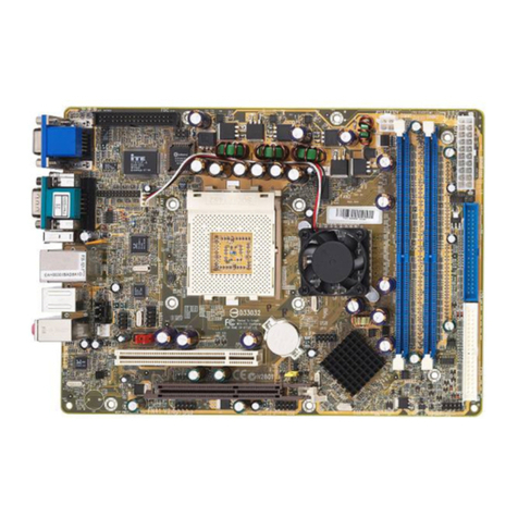
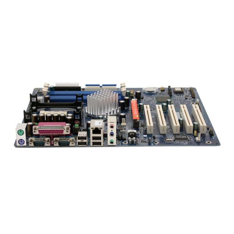
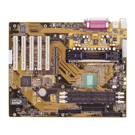
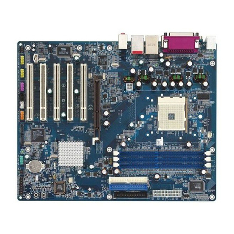
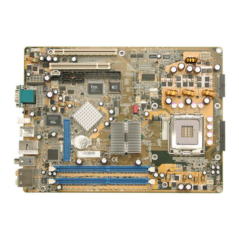
Shuttle AN51R User manual

AN51R
Socket 754
AMDAthlon TM 64 Processor
Based DDR MAINBOARD
User's Manual

MA10
Shuttle®AN51R
Socket 754
AMDAthlon TM 64 Processor
Based DDR Mainboard
Copyright
Copyright©2004 by Shuttle®Inc.AllRightsReserved.
This publication, including all photos, illustrations, and software, is protected under interna-
tional copyright laws, with all rights reserved. Reproducing any of the material contained
herein is prohibited without the consent of the publisher.
Disclaimer
Shuttle®Inc. shall not be liable for any incidental or consequential damages resulting from the
performance or use of this product.
This company makes no representations or warranties regarding the contents of this manual.
Information in this manual has been carefully checked for reliability; however, no guarantee is
given as to the correctness of the contents. In the interest of continued product improvement,
this company reserves the right to revise the manual or include changes in the specifications
of the product described within it at any time without notice and without obligation to notify any
person of such revision or changes. The information contained in this manual is provided for
general use by the customers.
Trademarks
Shuttle is a registered trademark of Shuttle Inc.
NVIDIAisaregisteredtrademarkof NVIDIA Corporation.
AMD,Athlon TM 64is registered trademarks ofAMDCorporation.
PS/2 is a registered trademark of IBM Corporation.
AWARD is a registered trademark ofAward Software Inc.
Microsoft and Windows are registered trademarks of Microsoft Corporation.
General Notice: Other product names used in this manual are ascribed to their respective
owners and acknowledged.

Thermalissue ishighly essentialforprocessors withaspeed of600MHzand above.
Hence,we recommendyou touse theCPU fanqualified byAMDor motherboard
manufacturer.Meanwhile,please makesureCPU andfanare securelyfastenedwell.
Otherwise,improperfan installationnotonly getssystemunstable butalsocould
damageboth CPUand motherboardbecause insufficient thermal dissipation.
Ifyou wouldlike to know more aboutthermal topicplease see AMD website for
detailedthermalrequirement throughtheaddress:
http://www.amd.com
WARNING

Ifyou’ve changed your CPU oroverclocked your system,the system mayfail toboot up,
even with a Clear CMOS jumper physically resetted. The reason is that NVIDIA’s new
nForce2 chipset introduces a way to reset a Clear CMOS jumper without removing a
chassis.Please followthe stepslisted below:
1. Turnoffyour computerandunplug thepower cable.Reconnectit after30seconds;
2. Press<Insert>andthenpressyourcomputer’s start button.Continueholding<Insert>
untilthesystem beginsthePOST (Power-OnSelfTest);
3. Immediatelypress<Del> toenter theBIOS;
4. Select‘Load OptimizedDefaults’ to return your systemto abootable condition;then
select ‘SAVE to CMOS and EXIT’;
5. Rebootyoursystem.
Moreover, if your system fails to boot up after you reset the CPU FSB, select “SAVE to
CMOS and EXIT” in the BIOS.After the system restarts, there is on screen a message
warningyounotto resetorturnoff your computer:
Warning! New setting is updating now
Do not Reset or Shutdown the system
Yoursystem worksafter theBIOS isupdated.
NOTICE

Statement of Shuttle Mainboard via the EMI Test
Shuttle mainboards have been via the EMI test in terms of series of regulations: EN55022/
CISPR22/AS/NZS3548ClassB,EN55024(1998/AS/NZS),EN4252.1(1994),EN61000,ANSI
C63.4 (1992), CFR47 Part 15 Subpart B, and CNS13438 (1997). The items tested are illus-
trated as follows:
(A)Voltage:AC110V/60HZ &AC230V/50HZ
(B) Tested Product Information:
Product Name: PC Mainboard
Status: Sample
ModelName:AN51R
S/N:N/A
CPU:
External Frequency: 200 MHz 3000+/ 3200+
Mouse Port: one port with 6 pins
Keyboard Port: one port with 6 pins
Parallel Port: one port with 25 pins
Serial Port: one ports with 9 pins respectively
1394 Port: one port with 6 pins
Mic-In & Center/Bass & Line-In & Rear-Out & SPDIF-Out & Front-Out Ports : one port
for each
LAN Port: one port with 8 pins (10Mbps/ 100Mbps)
USB Port: four ports with 4 pins respectively
DIMM Memory (optional): DDR 400 256 MB*2
Power Cable: Detachable and Shielded (with a GND pin)
Monitor:CRT
Maximum Resolution: 1280 X 1024 V:60Hz
All CPUs have completely been tested, and values offered by the worst EMI combination of
CPU external frequency are listed as follows:
(C) Remedy for the Tested Product & Its EMI Interference:
Remedy:N/A
EMIInterference:
Crystal:14.318MHz(X1)/25.00 KHz(X9)/32.768 MHz(X2)/24.576MHz(X3)/
25.000MHz(X6)/24.576 MHz(X7)
ClockGenerator: Zu1
Test Mode
1External Frequency
200 MHz CPU
3200+

(D) Supported Host Peripherals:
(E) Notices for Assembling Computers:
1. Cases should be made of iron or other metal that has good electric conductivity.
2. Cylinders in a case should be made of metal, and as having a mainboard mounted
in a case, make sure screws are all utilized and fastened on a mainboard.
3. An I/O shielding should be contacted with I/O metallic parts of a mainboard.
4. Cables should appropriately be arranged and fixed in a case. Follow instructions:
Ø Leave IDE cables not crossed upon CPU and SDRAM;
Ø Leave power cables minimum in length, and not crossed upon a mainboard;
Ø Leave CPU fan cables minimum in length, and not near CPU;
Ø Leave cables on panels and other spare cables tied in a computer case.
5. Make sure an EMI shielding attached to a case has properly been installed.
6. Make sure a 5.25" or 3.5" FDD and screws are fastened to an EMI shielding.
7. Make sure a case is closely in contact with EMI connected points.
8. Make sure there is no cleft in a case which is not deformed.
9. Make sure a PCI orAGP door is bound to a case.
10. Make sure cables of other devices (fans or some others) are fixed in a case.
Host Peripheral Product Name Model Name
#1 Case AN51R
#2 Power Supply (300W) ENP-0730
#3 Maxtor HDD (40GB) D740X-6L
#4 CODE DVD Player DVD-116

Important Safety Information
SAFETY INSTRUCTIONS
1. Pleasereadthesesafety instructionscarefully.
2. Pleasekeep this User‘sManual for later reference.
3. Pleasedisconnect this equipmentfromAC outlet before cleaning.Don‘t use liquid
orsprayed detergent forcleaning.
4. Forpluggableequipment, thesocket-outlet shallbe installednearthe equipment
andshall be easilyaccessible.
5. Pleasekeepthis equipmentfromhumidity.
6. Laythisequipment onareliable surfacewheninstall.A drop orfall couldcause injury.
7. Donot leavethis equipment in an environmentunconditioned, itmay damagethe
equipment.
8. Theopenings onthe enclosure are for airconvection henceProtect theequipment
fromoverheating.DO NOTCOVERTHE OPENINGS.
9. Makesure the voltageof thepower sourcewhen connect theequipment tothe
poweroutlet.
10. Placethepower cordsucha waythat people cannot steponit. Donotplace anything
overthepowercord. Thepowercordmust beratedforthe productandforthe voltage
andcurrent marked on the product’s electrical ratings label. Thevoltage and current
ratingof thecord should be greater thanthe voltageand currentrating markedon the
product.
11. Allcautions andwarnings on the equipment shouldbe noted.
12. Iftheequipmentis not useforlongtime,disconnecttheequipmentfrommainstoavoid
beingdamagedby transientover-voltage.
13. Neverpouranyliquidintoventilationopenings,thiscouldcausefireorelectricalshock.
14. CAUTION:The computeris provided witha battery-poweredreal-time clockcircuit.
Thereis adanger ofexplosion if battery is incorrectlyreplaced.
Replaceonlywith sameorequivalent typerecommendedby themanufacture.
Discardused batteriesaccording to themanufacturer’s instructions.
15. THE COMPUTER IS PROVIDED WITH CD DRIVES COMPLY WITHAPPROPRI-
ATESAFETY STANDARDSINCLUDING IEC 60825.
CAUTION :RISK OF EXPLOSION IF BATTERY IS REPLACED BY AN
INCORRECT TYPE. DISPOSE OF USED BATTERIES
ACCORDING TO THE INSTRUCTIONS
CLASS 1 LASER PRODUCT

- 1 -
TABLE OF CONTENTS
WHAT'S IN THE MANUAL.................................................................... 4
Quick Reference............................................................................................... 4
About This Manual ........................................................................................... 4
1 INTRODUCTION................................................................................ 5
1.1 TO DIFFERENT USERS ............................................................................. 5
FIRST-TIMEDIYSYSTEMBUILDER............................................................ 5
EXPERIENCEDDIYUSER ......................................................................... 5
SYSTEMINTEGRATOR............................................................................... 5
1.2 ITEM CHECKLIST: ...................................................................................... 6
2 FEATURES ........................................................................................ 8
2.1 SPECIFICATIONS ....................................................................................... 8
3 HARDWARE INSTALLATION..........................................................12
3.1 STEP-BY-STEP INSTALLATION............................................................... 12
STEP1 Install theCPU .............................................................................. 13
STEP 2 Set Jumpers ................................................................................. 14
STEP3 Install DDR SDRAM SystemMemory............................................ 14
STEP4Install InternalPeripherals inSystemCase .................................... 15
STEP5 Mount theMainboard on theComputer Chassis............................ 16
STEP6 ConnectFront Panel LEDs/Switches/Speaker/USBs .................... 17
STEP 7 Connect IDE ,Floppy Disk Drives................................................. 18
STEP8Connect OtherInternalPeripherals................................................ 19
STEP9 Connect thePower Supplies......................................................... 21
STEP10 InstallAdd-on Cardsin Expansion Slots ...................................... 21
STEP11 Connect External Peripherals to Back Panel ............................... 22
STEP12 System BootUp For the First-Time ............................................. 23
STEP13 InstallDrivers &Software Components ....................................... 24
3.2 JUMPER SETTINGS ................................................................................. 25
JUMPERS& CONNECTORSGUIDE........................................................ 26
Jumpers
Clear CMOS Setting (JP18)...................................................................... 28
Giga LAN Setting (JP21) .......................................................................... 29
1394 Setting (JP22).................................................................................. 29

- 2 -
Back Panel Connectors
PS/2Mouse & PS/2 Keyboard Port Connectors ........................................ 30
ParallelPortConnector .............................................................................. 30
COM1Port Connector ............................................................................... 30
ClearCMOS Button ................................................................................... 30
SPDIF-In Connector.................................................................................. 30
IEEE1394 Connector ................................................................................ 31
USB PortConnectors ............................................................................... 31
GigabitLAN Port Connector....................................................................... 31
Mic-InPortConnector ................................................................................ 31
Center/BassPortConnector ...................................................................... 31
Line-InPortConnector ............................................................................... 32
Rear-OutPortConnector ........................................................................... 32
SPDIF-OutPortConnector......................................................................... 32
Front-OutPortConnector ........................................................................... 32
Front Panel Connectors
HDD LED Connector (HLED) .................................................................... 33
GreenLED Connector (GLED) .................................................................. 33
HardwareResetConnector (RST).............................................................. 34
ATXPowerOn/Off SwitchConnector(PWON) ........................................... 34
EPMIConnector(EPMI)............................................................................. 35
Power LED Connector (PLED) .................................................................. 35
SpeakerConnector (SPEAKER) ............................................................... 35
Internal Peripheral Connectors
EnhancedIDE andFloppy Connectors(IDE1/IDE2 &FLP1) ...................... 36
SerialATA Connectors (SATA #1~4) .......................................................... 36
Other Connectors
ATXPower Supply Connectors(ATX1/CN8) .............................................. 37
CPUand SystemFan Connectors(FAN1/2/3)............................................ 38
IRHeader(JP8)......................................................................................... 38
AudioCD_IN Connectors (CN4/CN5) ........................................................ 39
AudioAUX_INConnector(CN6) ................................................................ 39
ExtendedUSB Headers(JP7/JP20) .......................................................... 40
FrontPanelAudioHeader (JP11)............................................................... 40

- 3 -
IEEE1394 Connector (JP15)..................................................................... 41
PowerButton(SW1) .................................................................................. 41
ResetButton(SW2) ................................................................................... 41
3.3 SYSTEM MEMORY CONFIGURATION ..................................................... 42
INSTALLMEMORY .................................................................................... 42
UPGRADEMEMORY................................................................................ 43
4 SOFTWARE UTILITY ......................................................................44
4.1 Mainboard CD Overview ......................................................................... 44
4.2 Install mainboard software Driver .......................................................... 44
4.2.A Install DirectX9 Utility Driver ......................................................... 45
4.2.B Install nVIDIA Chipset Driver ........................................................ 45
4.2.C Install Broadcom Giga LAN Driver............................................... 46
4.2.D Install nVIDIA USB2.0 Driver ........................................................ 46
4.3A View the User's Manual......................................................................... 47
4.3B View the NVIDIA RAID User's Guide .................................................... 47
5 BIOS SETUP ................................................................................... 48
5.1 ENTER BIOS ............................................................................................. 48
5.2 THE MAIN MENU ...................................................................................... 49
STANDARD CMOS FEATURES ............................................................... 51
ADVANCED BIOS FEATURES................................................................. 53
ADVANCED CHIPSET FEATURES .......................................................... 56
INTEGRATEDPERIPHERALS .................................................................. 59
POWERMANAGEMENT SETUP.............................................................. 62
PNP/PCICONFIGURATIONS .................................................................... 64
PCHEALTH STATUS................................................................................ 65
RATIO/VOLTAGECONTROL..................................................................... 65
LOAD FAIL-SAFE DEFAULTS .................................................................. 66
LOADOPTIMIZEDDEFAULTS ................................................................. 66
SETSUPERVISOR/USER PASSWORD................................................... 66
SAVE & EXIT SETUP................................................................................ 67
EXITWITHOUTSAVING ............................................................................ 67
Appendix A. Update Memory Configurations ............................................... 68

- 4 -
Quick Reference
Hardware Installation >> Step-by-Step ................................................Page 12
Jumper Settings >> A Closer Look.......................................................Page 25
Software Utility >> How to Install..........................................................Page 44
BIOS Setup >> How to Configure.........................................................Page 48
About This Manual
For First-Time DIY System Builder .........................................................Page 5
For Experienced DIY User ......................................................................Page 5
For System Integrator .............................................................................Page 5
WHAT'S IN THE MANUAL

- 5 -
1.1 To Different Users
First-Time DIY System Builder
Welcome to the DIY world! Building your own computer system is not as diffi-
cult as you may think. To make your first computer DIY experience successful,
right from the start, we have designed Chapter 3 Hardware Installation in a
step-by-step fashion for all the first-time DIY system builders. Prior to installa-
tion, we suggest you read the whole manual to gain a complete understanding
of your new AN51R mainboard.
Experienced DIY User
Congratulate on your purchase of the AN51R mainboard. You will find install-
ing your new AN51R mainboard is quite easy. Bundled with an array of onboard
functions, the highly-integrated AN51R mainboard provides you with a total
solution to build the stablest and most reliable system. Referring to section 3.2
Jumper Settings and Chapter 4 Software Utility, you will find how to work
out your new mainboard. Chapter 5 BIOS Setup also contains the relevant
information on how to tune up your system to achieve higher performance.
System Integrator
You have wisely chosen AN51R to construct your system. AN51R incorpo-
rates all the state-of-the-art technology of the nForce3 250 chipset from nVIDIA.
Each integrates the most advanced functions you've ever found in a compact
ATX board.
1INTRODUCTION

- 6 -
1.2 Item Checklist:
Check all items with your AN51R mainboard to make sure nothing is miss-
ing. A complete package should include:
-One Shuttle AN51R Mainboard
-One ATA 133/100/66 Ribbon Cable
-One Floppy Ribbon Cable
-One piece of one port 1394 Cable
-One Twin-Port USB Cable
-One piece of Serial ATA Cable
-Two pieces of Serial ATA Power Cord
SERIAL
ATA
V
S
O
KB 1
FAN1
1
W49V002AP
223503101
207GFSA
W
i
n
b
o
n
d
F
A
N
2
1
SPEAKER
EPMI
RST
PCI5
PCI4
PCI2
PCI3
PCI1
1
1
1
Front Audio
1
IR
AGP1
JP 11
1
JP 15
1394
LAN1
A
U
D
I
O
1
USB 2
A
T
X
P
W
R
USB 5&6
1
JP 7
SATA3
SATA4
SATA1
SATA2
TAIWANS
FB3741.10332 A6
n
VIDI
A
FORCE
3
150
n
T
M
USB 7&8
1
JP 18
1
JP 8
PWON
-
+
GLED
1
+
-
HLED
+
-
PLED
JP 19
SW1SW2
8
8
S
R
3
0
2
0
-
T
B
C
G
6
1
5
2
4
1.
3
0
3
0
4
A
O
P
T
ai
w
a
n
CN5
CN4
CN6
3A289T1344F
ALC650
1
1
1
JP22
JP21

- 7 -
-I/O Shielding
-AN51R User's Manual
NVIDIA RAID User's Manual
-One Bundled CD-ROM, including:
ØAN51R user's and nVIDIA raid manuals in PDF format
ØDirectX9 Utility Driver
ØnVIDIA Chipset Driver
ØBroadcom Giga Lan Driver
ØnVIDIA USB2.0 Driver
ØAward Flashing Utility

- 8 -
AN51R mainboard is dedicatedly designed for demanding PC users who desire high
performance and maximum intelligent features in a compact package.
2.1 Specifications
-CPU Support
AMD Athlon TM 64 on 754-pin SMT Socket.
-Chipset
nVIDIA nForce3 250 Single Chip for AMD Athlon64 CPU.
-Jumperless CPU Configuration
Soft-configuration FSB (The FSB speed is software configurable from 200MHz
to 280MHz in the Ratio/Voltage Control of BIOS setup program).
-Integrated Serial-ATA (SATA) Interface
It compliants with SATA specification.
It supports dual channel SATA, 1.5 Gb/s per channel and power down
capabilities.
-External RSPI Serial-ATA PHY Interface (Marvell 3020)
It compliants with SATA specification.
It supports dual channel SATA, 1.5 Gb/s per channel and power down
capabilities.
-AC'97 Audio
Realtek ALC650 include SPDIF-IN function.
It compliants with AC97 2.2 specification.
5.1-Channel output but Line-in & Mic-in are shared with Rear-out & Center/
Bass that can be setting by device panel under OS.
Rear-out & Center/Bass have two set independent header which aren't
shared with any function.
It supports CD-IN/AUX-IN/Front Audio Panel/SPDIF-IN connectors & headers.
nForce 3 250 chipset build-in SPDIF-OUT that support pass-through function.
-Versatile Memory Support
Three 184-pin DIMM slots to support up to 3.2GB bandwidth for PC1600,
PC2100, PC2700, PC3200 compliant with DDR SDRAM module.
2 FEATURES

- 9 -
System memory supports 64/128/256/512Mb technologies up to 3GB
capacity max and 1GB per DIMM.
-AGP Expansion Slot
Provides single 1.5V 8x AGP slot which supports 4X / 8X AGP devices.
-PCI Expansion Slots
It provides five PCI slots and supports 5788 Gigabit Lan (GbE)/VT6307 2
ports IEEE 1394 firewire on board.
-8 USB 2.0/1.1 Interface Onboard
4X USB ports on back panel and two extended USB headers (4 ports) on front
panel.
-Gigabit Ethernet Controller (BCM5788KFB)
10/100/1000 Mbps operation rate. Support Wake-on-Lan (WOL) function.
-IEEE 1394 (VT6307)
Compliant with 1394 OHCI specification revision V1.0 and V1.1. Support
400Mb/s, 200Mb/s, 100Mb/s data transfer rate.
-I/O Interface
Provides a variety of I/O interfaces:
Ø1 x PS/2 Mouse
Ø1 x PS/2 Keyboard
Ø1 x Serial port
Ø1 x Parallel port
Ø1 x Clear CMOS button
Ø1 x SPDIF-In port
Ø1 x 1394 port
Ø4 x USB ports
Ø1 x Gigabit Lan port
Ø1 x Mic-In port
Ø1 x Center /Bass Out port
Ø1 x Line-In port
Ø1 x Rear-Out port
Ø1 x SPDIF-Out port
Ø1 x Front-Out port

- 10 -
-PCI Bus Master IDE Controller Onboard
Two Ultra DMA 133/100/66/33 bus master dual-channel IDE ports support up
to two IDE devices (one Master and one Slave per channel).
The IDE bus implentents data transfer speeds to 133/100/66/33 Mb / Sec and
also supports PIO mode 0, 1, 2, 3, 4.
80-pin cable backward compatible legacy ATAPI devices, ATAPI IDE CD-
ROM, CD-R, CD-RW and LS-120 supports.
-ATX Power Supply Connector
ATX power supply unit can be connected to the onboard 20-pin ATX power
connector, and 4-pin ATX power connector. The unit supports Suspend and
Soft-On/Off modes by the dual-function power button.
-Advanced Configuration and Power Interface
Features four power-saving modes: S1 (Snoop), S3 (Suspend to RAM), S4
(Suspend to DISK), and S5 (Soft-Off). ACPI provides more efficient energy-
saving features controlled by your operating system that supports OS Direct
Power Management (OSPM) functionality.
-System BIOS
Provides licensed Award BIOS V6.0 PG on the 4Mb Flash ROM, and sup-
ports Green PC, Desktop Management Interface (DMI).
-Form Factor
System board conforms to the Full ATX specification.
Board dimension: 305 x 244 (mm).
-Advanced Features
ØLow EMI - Built in spread spectrum. Unused PCI/SDRAM slots are shut off
by the automatic clock for reducing EMI.
ØDual Function Power Button - The system can be in any of the two
states: one is Suspend mode and the other is Soft-Off mode. Pushing the
power button for less than 4 seconds places the system into Suspend
mode. When the power button is pressed for longer than 4 seconds, the
system will enter Soft-Off mode.
ØModem Ring Power-On - The system can be powered on automatically
by the activation of modem ringing.
ØCPU Multiplier Setting - This item allows users to adjust CPU Multiplier
in BIOS.

- 11 -
ØCPU/RAM/AGP Voltage Setting - These items allow users to adjust
CPU/RAM/AGP Voltage in BIOS.
-Intelligent Features
ØVoltage Monitoring - Monitors various voltages of key elements, such as
the CPU, and other critical system voltage levels to ensure a stable current
passing through mainboard components.
ØFan Status Monitoring -To prevent the CPU from overheating, the CPU
fan is monitored by RPM, with which the cooling fan is required.
ØTemperature Monitoring -This item allows users to make sure whether
the CPU or system runs under a suitable temperature.

- 12 -
Before removing/installing any of these devices: CPU, DIMMs, Add-On
Cards and Cables, please unplug the onboard power connector.
This section outlines how to install and configure your mainboard. Referring to the
following mainboard layout helps you identify various jumpers, connectors, slots
and ports.
3.1 Step-by-Step Installation
Accessories Of AN51R
3HARDWAREINSTALLATION
KB 1
FAN1
1
W49V002AP
223503101
207GFSA
W
i
n
b
o
n
d
F
A
N
2
1
SPEAKER
EPMI
RST
PCI5
PCI4
PCI2
PCI3
PCI1
1
1
1
Front Audio
1
IR
AGP1
JP 11
1
JP 15
1394
LAN 1
A
U
D
I
O
1
USB 2
A
T
X
P
W
R
USB 5&6
1
JP 7
SATA3
SATA4
SATA1
SATA2
TAIWAN
S
FB3741.10332A6
n
VIDI
A
FORCE
3
150
n
T
M
USB 7&8
1
JP 18
1
JP 8
PWON
-
+
GLED
1
+
-
HLED
+
-
PLED
JP 19
SW1 SW2
8
8
S
R
3
0
2
0
-
T
B
C
G
6
1
5
2
4
1
.
3
0
3
0
4
A
O
P
T
a
iw
a
n
CN5
CN4
CN6
3A289T1344F
ALC650
1
1
1JP22
JP21
PS/2 Keyboard/Mouse
Port Connectors
Serial Port Connector
Parallel Port Connector
Clear CMOS Button
IEEE1394 Port /USB
Connectors
Giga LAN Port /USB
Connectors
Mic-In / Center-Bass
Line-In / Rear-Out
SPDIF-Out / Front-Out
Port Connectors
1.5V AGP Slot
VIA VT 6307
IEEE 1394 Chipset
Five PCI Slots
Realtek ALC650
Extended 1394a
Headers - JP 15
PowerSwitch-SW1/
ResetSwitch-SW2
CD_IN Connectors
-CN4/CN5
AUX_IN Connector
- CN6
FAN3
FAN2
F
l
o
p
p
y
C
o
n
n
e
c
t
o
r
T
w
o
I
D
E
C
o
n
n
e
c
t
o
r
s
S
u
p
e
r
I
/
O
&
H
/
W
M
o
n
i
t
o
r
i
n
g
-
I
T
8
7
1
2
F
-
A
A
T
X
P
o
w
e
r
C
o
n
n
e
c
t
o
r
-
A
T
X
1
Three DIMM Slots
ATX12V Power Connector - CN8
nVIDIA nForce3 250 Chipset
Socket 754 FAN1
SPDIF-In Port
Connector
Front Panel Audio
Header - JP 11
SATA 3 & 4
Extended USB 5&6 and
7&8 Headers -JP7/JP20
Clear CMOS - JP18
IR Header - JP8
JP8
SATA1&2
+PLED-
PWON
+HLED-
GLED+
Front Panel
Header - JP 19
GIGA LAN Select-JP21
1394 Select-JP22

- 13 -
Step 1
Install the CPU
1. Locate the CPU ZIF (Zero Insertion Force) socket on the upper-right sector
of your mainboard (between the back panel connectors and the DIMM
memory slots).
2. Pull the CPU ZIF socket lever slightly sideways away from the socket to
unlock the lever, and then bring it to an upwardly vertical position.
3. Place your AMD Athlon TM 64 processor in the socket. Note that the CPU's
edges have been purposely designed non-symmetrically to prevent from in
serting the processor in the wrong direction. The following diagram demon
strates the correct placement of the CPU in the ZIF socket.
4. Slightly push the AMD Athlon TM 64 processor into the socket without apply
ing excessive force while making sure there is no gap between CPU and
socket. Then lower the socket-lever all the way down to its horizontal posi-
tion and lock it to secure the CPU in place.
5. The AMD Athlon TM 64 processor requires a set of heatsink/fan to ensure
proper cooling of the processor. If heatsink/fan have not been already
mounted on your CPU, you must purchase the heatsink/fan separately and
have it in stalled. Plug the cable throught the heatsink/fan in the CPU fan
power connector located nearby. Note that there are several types of CPU
fan connectors. Normally, if your mainboard supports the hardware moni
toring function, a 3-pin fan power connector should allow your system to
detect the CPU fan's speed. The CPU fan can also run with a 2-pin fan power
connector, however, detection of CPU fan's speed is not supported. An
other type of CPU fan may feature a large 4-pin fan power connector, which
does not support CPU fan's speed detection and must be directly connected
to the system's power supply unit. Please refer to the following diagram.
Lever
A Triangle
Mark
Lever
AMD CPU
Z
A
D
A
3
1
0
0
A
E
P
5
A
J
A
A
A
I
C
0
3
1
9
P
A
W
F
3
5
8
1
9
7
2
4
0
0
2
5
Table of contents
Other Shuttle Motherboard manuals

Shuttle
Shuttle Spacewalke AK21 User manual

Shuttle
Shuttle FX43G User manual

Shuttle
Shuttle FB65 User manual

Shuttle
Shuttle AV49 User manual

Shuttle
Shuttle HOT-679V User manual

Shuttle
Shuttle MS52P User manual

Shuttle
Shuttle MV21 User manual

Shuttle
Shuttle MK35V User manual

Shuttle
Shuttle Spacewalker AK31 User manual

Shuttle
Shuttle Spacewalker MV25 User manual

Shuttle
Shuttle MB47N User manual

Shuttle
Shuttle FB95 User manual

Shuttle
Shuttle MS11 User manual

Shuttle
Shuttle FB52 User manual

Shuttle
Shuttle Spacewalker MK20 User manual

Shuttle
Shuttle HOT-623 User manual

Shuttle
Shuttle FB62 User manual

Shuttle
Shuttle MV43P User manual

Shuttle
Shuttle HOT-579 User manual

Shuttle
Shuttle MV43V User manual