SI Solo 3 675 EXTERNAL INDOOR User manual

Solo 3
Indoor
675 External
Installation Instructions
INSTALLERS: PLEASE LEAVE THIS MANUAL WITH THE OWNER.
Doc. #400202 |v. 1.0 |25 January 2023

Scan the QR code to view the SI warranty for this product.
Technical Support: 512.832.6939 screeninnovations.com
Hours of Support: 7:30am – 5pm CST [email protected]
Please use this QR Code to access the updated installation instructions and related
documents.

TABLE OF CONTENTS
Operating And Care Of Your Screen ........................................................4
Before Proceeding .........................................................................4
Parts In The Box – Solo 3 675 External – Indoor .............................................5
Installation Methods .......................................................................6
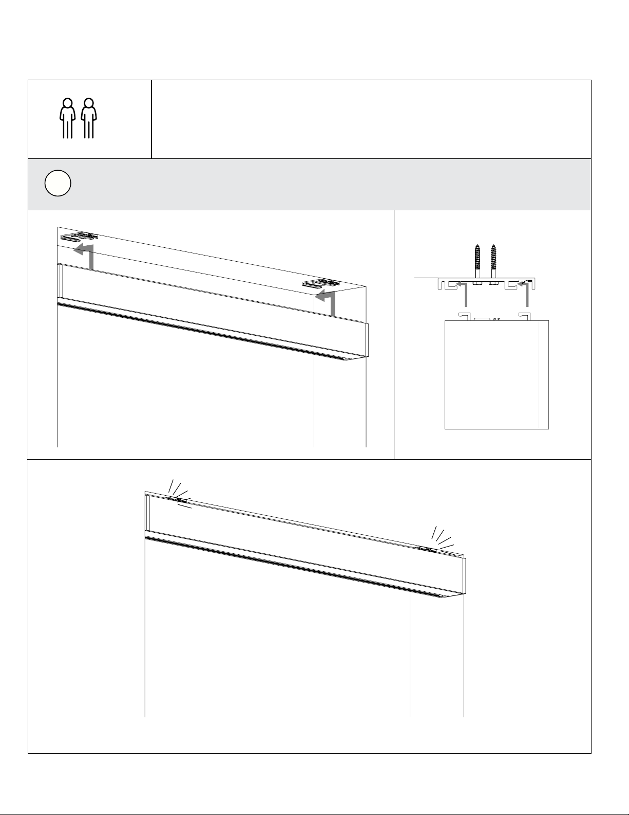
Mounting ..................................................................................6
Brackets .................................................................................7
Cassette..................................................................................8
Through Bolting Cassette ................................................................9
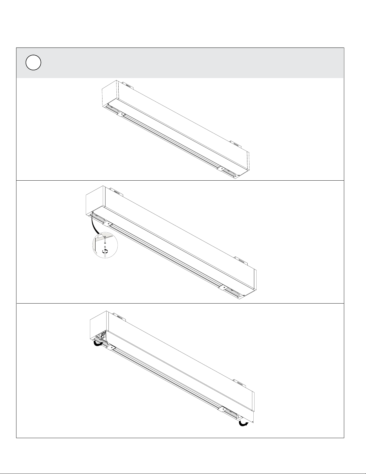
Method 1 Installation - Assembled ..........................................................9
Unpacking ............................................................................. 10
Weight Bar ............................................................................11 - 12
Fascia Door ............................................................................ 13
Method 2 – -Disassembled..................................................................9
Unpacking ............................................................................. 14
Material Roll Removal................................................................. 15 - 16
Mounting Cassette ..................................................................... 17
Material Roll Reinsertion ................................................................ 18
Fascia Door ............................................................................ 19
Installation – Ceiling Mount – Moab........................................................20
Wiring .................................................................................. 21 - 22
Inside Cassette Wiring – 24v DC......................................................... 21
Detailed Low Voltage Power And 485 Control Wiring (DC Motor) ....................... 21
Inside Cassette Wiring – 110v/220v AC ...................................................22
Commissioning Guide Reference – Moab ..................................................23
Controls Guide Reference .................................................................23

4
• Operation of the screen systems should only be performed by responsible parties.
• Always check the path of the Solo 3 Screen before operating to ensure that the path is clear of furniture
or obstacles that could prevent full operation. Monitor the Solo 3 Screen for smooth operation through
its entire range. Operating a Solo 3 Screen unattended may lead to damage from obstructions or other
causes.
• Fabric maintenance and cleaning– Solo 3 Screen fabric is subject to debris under normal use or in
storage, requiring occasional maintenance and cleaning. While fading and wear over time are normal,
debris could accelerate this wear. Screen fabrics can be cleaned with gentle soap and water.
OPERATING AND CARE OF YOUR SCREEN
Preparing for installation: It is crucial that all installations are planned out carefully before
specifying a screen order.
• If drilling through the cassette is required, the cassette must be square or the door will not line up,
causing poor operation.
• Electrical work should be performed following appropriate electrical codes and regulations by a licensed
electrical professional.
• Use fasteners appropriate for the structure the Solo 3 Screen will be mounted to.
• Do not use any sharp blades when opening the packaging.
Read the instructions in their entirety before proceeding. Actions contrary to the instructions
invalidate the warranty and may result in serious damage and/or injury.
BEFORE PROCEEDING

5
(6) Mounting Screws
(2/3) Ceiling Mount Brackets
(2/3) Wall Mount Brackets
Case Assembly
Mounting Bracket Options
Red Straps
Required
Hardware
PARTS IN THE BOX – SOLO 3 675 EXTERNAL – INDOOR
Screen
Note: Not Provided.
RF Remote
(1 per RTF screen)
Included remotes’ form factor may
vary, however functionality and
performance is consistent.
IR Remote
RJ45 Coupler
(AC – 485 screens only)
DUOCoup
(for low voltage 485)

6
INSTALLATION METHODS
MOUNTING
MOUNTING NOTES:
• To ensure best results, read all instructions before assembly.
• Unpacking the box– lay cassette, fabric tube, and material roll on a soft, clean surface during the
installation process. When removing from the box, ensure the assembly is kept horizontal to prevent
damage.
• The following section, Mounting, of the indoor Solo 3 675 External instructions applies to ALL
installations, regardless of method, determined above.
• When utilizing either method, especially METHOD 1, make certain there are enough installers/
hoisting equipment to safely lift the cassette (and/or material) onto the brackets. Brackets must be
level and in-line with one another before attempting to lift cassette onto brackets. Use safe lifting
and rigging techniques.
• For METHOD 2, ensure installation is complete by returning to page 16 after securing the casette to
the brackets.
1
2
Before installation, determine your installation method according to your product order and installation
preferences. The indoor Solo 3 675 External may be installed preassembled or separately (fabric tube and
material installed after the cassette).
METHOD 1 –Assembled
METHOD 2 – Disassembled (Cassette only)

7
MOUNTING – BRACKETS
1Use appropriate fasteners to mount the ceiling brackets to structural supports. Mount brackets
between (2–6’’) from the opening ends (additional brackets are intended to prevent cassette sag
and should generally be applied to the middle of the cassette). All brackets must be in line and
level to each other.
BEFORE INSTALL– Check upper corners of the opening clearance, as necessary, to prevent interference
with the cassette and end caps.
Ceiling MountWall Mount
NOTE: Ensure the fasteners used are adequate for the weight of the Solo 3 Screen and the structure.
2– 6”
2– 6”

8
For METHOD 1, lift and secure assembly onto brackets. Once the bracket engages, the cassette will
“click” into place.
Installation requires two or more people and/or hoisting equipment.
Please use safe lifting and rigging techniques.
2+
2
MOUNTING – CASSETTE

9
MOUNTING – THROUGH BOLTING CASSETTE
NOTE: Be careful not to over-torque or aggressively drill retention hardware when mounting
the cassette as deformation to the case could occur; this is especially important when ceiling
mounting. The structure behind the mounting points should be at and level.
WARNING! Select a screw or anchor type that has a shallower head prole to eliminate the risk of
contact with the screen material roll. Damage to the material caused by anchoring is not covered
under warranty. Before starting, ensure the screws or anchors being used are of a quantity, size,
and type compatible with the structural substrate you are mounting to, and rated for the weight
being carried. Weight can be found on the shipping documents or on the box label.
3
XL Cassette Mount Cassette Mount

10
Starting with the cassette secured onto the brackets, unscrew each end of the door
(counterclockwise), then open the assembly to access the inside.
1
METHOD 1 INSTALLATION – UNPACKING

11
Remove both of the exposed red weight bar clips (2) by removing the attached screws from the
bracket.
2
METHOD 1 INSTALLATION – WEIGHT BAR

12
Next, remove the screw attached to the weight bar from the red weight bar clips.
Attach the magnetic endcap to the weight bar.
3
4
METHOD 1 INSTALLATION – WEIGHT BAR

13
To secure the fascia door, set the door into the cassette; the door will hook in by gravity, as seen
in the images below. Secure with screws.
5
METHOD 1 INSTALLATION – FASCIA DOOR

14
Remove both of the exposed red weight bar clips (2) by removing the attached screws from the
brackets.
2
METHOD 2 INSTALLATION – UNPACKING
Starting with the cassette on a soft, clean surface, remove the screws from the fascia door and
open to reveal the inside.
NOTE: The following section of the Solo 3 Indoor 675 External instructions applies to separately
assembled projects where the cassette is installed prior to the fabric tube and material.
1

15
METHOD 2 – MATERIAL ROLL REMOVAL
Using the red straps, loop the straps under the material roll, being careful to avoid the material and
any obstructions. With the help of the straps on both the ends, slowly pull out material roll and set
it aside.
Attach the magnetic endcap to the weight bar.
3
4

16
METHOD 2 – MATERIAL ROLL REMOVAL
Using the red straps, loop the straps under the material roll, being careful to avoid contact with the
material or any obstructions. With the help of the straps on both the ends, slowly pull out material
roll and set it aside.
5
Undo the silver safety screws, then press the latch as shown.
4

17
Lift and secure the cassette onto the brackets. Once the bracket engages, the cassette will “click”
into place.
Installation requires two or more people and/or hoisting equipment.
Please use safe lifting and rigging techniques.
2+
6
METHOD 2 – MOUNTING CASSETTE

18
With the cassette mounted, open the door and slide the material roll with mounting plates on
each end into the cassette. Each end will “click” into place as the brackets engage.
NOTE: The roll must remain level while installing into the cassette.
Fasten the silver safety screws on the mounting plates to secure the material roll. Plug motor
power cable into the barrel connector located in the cassette.
This step is required for safety. Back safety screws out before installation. Must be re-engaged
after installing material roll.
7
8
METHOD 2 – MATERIAL ROLL REINSERTION

19
To close the fascia door, set the door into the cassette; the door will hook in by gravity. Secure
with screws.
9
METHOD 2 – FASCIA DOOR

20
2
INSTALLATION – CEILING MOUNT – MOAB
Push cassette all the way to the anges and ceiling; ne tune as needed with a mounting key.
1
Plug the motor power cable into the barrel connector (AC power), located within the cassette, or the
terminal blocks (DC power) to connect Moab (see pages 5 - 7 for power options).
The Moab board may be placed or removed from the internal PCB mounting plate by gently shifting
the entire board up to remove, down to reattach the four (4) standoffs.
If using low voltage, use the included DUOCoup to facilitate the wiring connections.
Upon reattachment, the board will tactically “click” and snap into place.
NOTE: If you plan to permanently remove/relocate externally Moab, carefully review the
Moab instructions to determine all the various options.
Table of contents
Other SI Projection Screen manuals

SI
SI Nano Box User manual

SI
SI 5 SERIES User manual

SI
SI FIXED 5 Series User manual

SI
SI ZERO EDGE PRO User manual

SI
SI 7 SERIES FIXED User manual

SI
SI ZERO EDGE PRO User manual

SI
SI Dynamic 2TB User manual

SI
SI Short Throw Lift Motorized Screen User manual

SI
SI Solo 2 User manual

SI
SI Solo/Pro 2 User manual
Popular Projection Screen manuals by other brands

Elite Screens
Elite Screens Kestrel FE100H brochure

Celexon
Celexon HomeCinema 1000027204 operating instructions

Screen Technics
Screen Technics CINEMAPRO instructions

Elite Screens
Elite Screens GolfSim Portable Series user guide

Da-Lite
Da-Lite Floor Model C instruction manual

Draper
Draper Acumen M XT1000E instructions