Sibata LD-5R User manual

CODE 080000-73
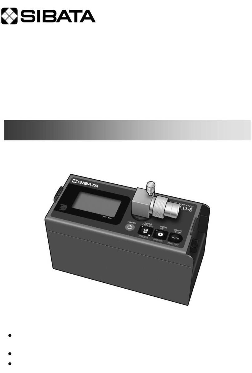
DIGITAL DUST INDICATOR
Thank you for purchasing this product.
This operation manual describes precautions that are important for preventing accidents as
well as procedures used to handle the product.
Read this operation manual and the attached warranty thoroughly before use, and use the
product correctly.
After reading this operation manual and the warranty, keep them handy for future reference.
OPERATION MANUAL

2
Table of Contents
Before Use..............................................................................................................4
Safety Precautions ...............................................................................................4
1About This Product .........................................................................................7
1-1 Overview....................................................................................................................7
1-2 Main Features............................................................................................................7
1-3 Product Contents .......................................................................................................8
1-4 Attaching the Shoulder Belt .......................................................................................8
2Description of the Parts..................................................................................9
3Description of the Main Screens and Parts.................................................11
3-1 Screens During Measurement ................................................................................. 11
3-2 Standby Screens .....................................................................................................12
3-2-1 Measurement Mode Screens ...........................................................................13
3-2-2 Setting Modes...................................................................................................14
3-2-3 Description of Icons ..........................................................................................16
3-2-4 Screen Displayed When the Measurement Is Finished....................................17
3-2-5 Remaining Battery Level Display......................................................................18
4Power Supplies..............................................................................................18
4-1 Batteries...................................................................................................................18
4-2 Backup Battery ........................................................................................................19
4-3 AC Power Supply.....................................................................................................20
5Replacing the Filters .....................................................................................21
5-1 Types of Filters ........................................................................................................21
5-2 Replacing the Filters ................................................................................................21
5-3 Attaching the Filter Covers ......................................................................................22
6Operating the Air Sampling Port Cap ..........................................................23
6-1 During BG Measurement and SPAN Measurement ................................................23
6-2 During Dust Measurement.......................................................................................23
6-3 Removing the Air Sampling Port..............................................................................23
7Operating the Scattering Plate Knob...........................................................24
7-1 During BG Measurement and Dust Measurement ..................................................24
7-2 During SPAN Measurement.....................................................................................24
8Measuring Samples.......................................................................................25
8-1 Measurement Procedures .......................................................................................25
8-2 Preparing for the Measurement ...............................................................................26
8-2-1 Operating the Power Switch .............................................................................26
8-2-2 BG Measurement Mode—BG Subtraction Function.........................................26
8-2-3 SPAN Measurement Mode—Sensitivity Correction..........................................27
8-3 Selecting the Measurement Mode ...........................................................................28
8-3-1 Types of Modes ................................................................................................28
8-3-2 One Minute Measurement Mode and Other Modes (Countdown Timer

3
Measurements)................................................................................................28
8-3-3 Timed Measurement Modes .............................................................................29
8-3-4 Timed Measurement Mode—Setting a User Designated Measurement Time .30
8-3-5 Manual Measurement Mode.............................................................................31
8-4 Starting the Measurement .......................................................................................31
8-5 During Measurement ...............................................................................................32
8-5-1 LCD Screen Sleep Function .............................................................................33
8-6 Finishing the Measurement .....................................................................................34
8-6-1 Countdown Timer Measurements and Timed Measurements ..........................34
8-6-2 Manual Measurements .....................................................................................34
9Functions .......................................................................................................35
9-1 Mass Concentration Conversion..............................................................................35
9-2 Entering the K Factor...............................................................................................36
9-3 Log Setting Mode.....................................................................................................36
9-3-1 Viewing the Log List..........................................................................................36
9-3-2 Log Recordings ................................................................................................37
9-3-3 Log Recording Procedure.................................................................................37
9-3-4 Erasing the Log ................................................................................................38
9-3-5 Logging Cycle Time ..........................................................................................38
9-3-6 Remaining Memory Capacity ...........................................................................38
9-4 Basic Setting Mode..................................................................................................39
9-4-1 Operation..........................................................................................................39
9-4-2 Description of the Setting Items........................................................................40
10 Communication Specifications ....................................................................42
10-1 Output During Manual and Timed Measurements ...................................................42
10-2 Output During Countdown Timer Measurements ....................................................42
10-3 Communication Commands and Control.................................................................43
10-3-1 Reading Commands.........................................................................................43
10-3-2 Operating Commands ......................................................................................45
10-3-3 Writing Commands ...........................................................................................45
11 Output Specifications (Output Connector) .................................................47
11-1 Analog Output..........................................................................................................47
11-2 Insulation Pulse Output............................................................................................47
12 Troubleshooting ............................................................................................48
13 Specifications ................................................................................................50
14 Precautions for Maintenance, Storage, and Transport ..............................52
15 Warranty.........................................................................................................53
16 Preferred Procedures for Requesting Repairs to Products Used in
Environments Exposed to Asbestos ...........................................................54
17 Disclaimers ....................................................................................................55

4
Before Use
About This Operation Manual
Information in this operation manual is subject to change without notice in the
interest of product improvement.
Every effort has been made to ensure that the information contained in this
operation manual is correct. If you discover any errors or omissions, however,
please contact your Sibata representative.
The copyright of this operation manual belongs to Sibata Scientific Technology
Ltd. This operation manual, or any part thereof, may not be reproduced, reprinted,
or altered in any form without prior written permission from Sibata Scientific
Technology Ltd.
Safety Precautions
The precautionary information in this operation manual is provided to ensure the
safe use of the product and to prevent property damage and injury to you and other
people.
All of the precautionary information is important for ensuring safety. Therefore, be
sure to read and understand the information thoroughly before using the product
and observe it during use.
Users (Important)
This product should only be operated by trained and experienced operators that
understand the specialized technology and dangers involved. Untrained or currently
being trained operators should only operate the product under close supervision by
a person that is already trained or has sufficient specialized experience.
This operation manual is written assuming the product will be operated by a person
that understands the risks of operating the product.
Graphical Symbols
The degree of danger involved in using the product without observing the indicated
precautionary information is indicated by one of two labels: WARNING or
CAUTION. Always observe the precautionary information indicated with these
labels, which is important for ensuring safety.
Labels Indicating Degrees of Damage or Injury
Indicates a potentially hazardous situation which, if
not avoided, will result in serious injury or death.
Indicates a potentially hazardous situation which, if
not avoided, may result in injury or equipment
damage.

5
When installing this product, always use a sturdy tripod or stand.
Check the AC adapter cord for cuts or other damage to the cable jacket before
operating the instrument. Do not step on or place heavy objects on the cord.
Using a damaged power cord could result in a fire or electric shock.
This product is not explosion proof, so do not use it near combustible or
flammable materials.
Do not use a damaged AC adapter cord or loose power outlet. Doing so could
result in a fire, electric shock, or other hazards.
Do not connect the AC adapter into an outlet with multiple items sharing the same
extension cord or plug adapter. Doing so could result in a fire or electric shock.
Do not touch the AC adapter cord or outlet with wet hands. Doing so could result
in an electric shock.
Do not attempt to disassemble or modify the product. Doing so could result in an
accident or fire.
Do not permit water, other liquids, or gases to enter the product. Doing so could
result in a fire or malfunction.
If a problem occurs during operation, immediately stop operating the product, and
remove the cause.
If it is determined that the product caused the problem, turn OFF the power
switch, disconnect the AC adapter from the power outlet, and then contact your
Sibata representative. Never operate the product if it is not functioning normally.
Also, never allow anyone other than a qualified service engineer to disassemble
or modify the product. Doing so could result in an accident or malfunction.
Unplug the AC adapter from the power outlet and remove the battery from the
battery case before cleaning or inspecting the product.
When not in use, unplug the AC adapter from the power outlet and remove the
battery from the battery case before storing the product.
It is dangerous to look directly at the beam of the laser in the laser diode used in
this product. Accordingly, never disassemble or modify the interior of the
detector. Also, never check the laser light inside the detector with the air
sampling port removed and the power switch turned ON.
Never block the exhaust port.

6
This product is intended for measuring dust levels. Do not use it for any other
purpose not indicated in this manual. Doing so could result in malfunction.
The normal operating temperature range of this product is 0 to 40 °C, with
humidity between 5 and 90 % RH (and no condensation). Operating the product
outside these temperature and humidity ranges could reduce performance,
shorten the service life, or cause malfunction.
Never attempt to connect to the connector using wire or other metal objects, or
any other method not specified in this manual. Doing so could result in
malfunction.
Do not subject the product to strong impacts or drops. Doing so could result in an
accident or malfunction.
Do not lift or carry the product by holding the air sampling port. Doing so could
damage the product.
Level the product and secure it to prevent tipping over. Not doing so could result
in an accident or malfunction.
Do not operate or store the product near a fire. Doing so could result in an
accident or malfunction.
Keep the product away from sources of noise. Do not operate the product in
locations with a strong magnetic field.
Do not apply water directly to this product. Doing so could result in malfunction.
Do not insert screws or other foreign objects into the air sampling port. Doing so
could cause a malfunction. If any foreign object gets inside the air sampling port,
turn OFF the power switch, disconnect the power cord from the power outlet, and
then contact your Sibata representative.
Please be aware that in the unlikely event of a product failure, Sibata bears no
responsibility to compensate for data not acquired or recorded, and is not
responsible for loss of data or for other direct or indirect damages incurred from
such loss. Be sure to back up data on a regular basis in case of an accident or
failure.

7
It is small and lightweight, which simplifies transport and measurement
layout procedures.
Since a color graphics LCD has been adopted for the display, visibility is
excellent.
When the LCD screen is OFF, the operational status can be checked from
a distance via the LED indicator.
The trend graph display is convenient for visualizing temporal fluctuations
in dust concentration.
It is not necessary to move to a different screen to record the measurement
data.
Filter replacement is easy and maintenance is simple.
If you pre-configure the units as mg/m3or μg/m3, values converted to mass
concentration can be displayed. (You must calculate the K factor and then
set it in this product.)
The mass concentration conversion will be reflected only in the measured
values in the LCD screen. It will not be reflected in the output or log data.
1 About This Product
1-1 Overview
This product is a dust indicator that makes use of scattered laser light.
When airborne dust in a darkened room is irradiated with light, if the physical
properties of the dust are kept under the same conditions, the amount of light
scattered by the dust is proportional to the mass concentration. Using this
principle, the concentration of airborne dust can be measured as a relative
concentration.
The relative concentration obtained with the dust indicator must be converted to
the mass concentration.
Accordingly, a mass concentration conversion factor is determined based on
consideration of various factors including the particle size, distribution, specific
gravity, form, and optical properties.
In comparison to the filtration collection method, a relative concentration indicator
has the advantage of obtaining a large amount of data in a short time. If the
temporal and spatial fluctuations of airborne dust are being tracked, they can be
evaluated just from the relative concentration, so the relative concentration
indicator can be used to simplify the measurement process in this case.
1-2 Main Features

8
Attachment
buckle
Shoulder belt hooks
1-3 Product Contents
Check the package contents before using the product.
LD-5R main unit ································································ 1
AC adapter (with four types of adapter plugs) ···································· 1
AA alkaline batteries (for checking operations)··································· 6
Shoulder belt ·············································································· 1
Operation manual (Japanese, English, Selecting the Interface Language) ····· 1 for each
Manufacture's Inspection Result ····················································· 1
Warranty···················································································· 1
Pump filter ················································································· 1
Purge filter ················································································· 1
(The pump and purge filters are installed in the main unit.)
Backup lithium battery ·································································· 1
(Installed in the main unit)
1-4 Attaching the Shoulder Belt
There are shoulder belt hooks on both sides of the main unit at the top (marked
with a .)
Pass the ends of the shoulder belt through the holes in the shoulder belt hooks.
Fold the ends over and pass them through the attachment buckles as in the figure.

9
Never block the exhaust port.
Operation of the LED Indicato
r
When the LCD is OFF, the LED indicator
displays the operational status.
Standby and stopped
(measurements finished):
Orange, flashing
Measuring: Green, flashing
→See 8-5-1 LCD Screen Sleep Function.
2 Description of the Parts
①LCD screen
②Air sampling port
③Panel sheet
④Scattering plate knob
⑤Exhaust port
⑥Battery case cover
⑦Shoulder belt hook
⑧Power switch (POWER)
⑨DC jack (DC12V)
⑩Output connector (SIGNAL)
⑪USB/mini B (USB)
⑫LED indicator
Main Unit
The DC jack shape is different than on models
up to LD-5R Ver. 1.03 (Item Code 080000-72).
The AC adapter is also different.

10
⑬Purge filter cover (PURGE FILTER)
⑭Pump filter cover (PUMP FILTER)
⑮Tripod attachment screw (TRI POD)
⑯[ESCAPE] switch
⑰[ENTER] switch
⑱[UP] switch
⑲[DOWN] switch
⑳[START/STOP] switch
Bottom of the Main Unit
Main Unit Panel

11
3 Description of the Main Screens and Parts
3-1 Screens During Measurement
The display items for each part change with the screen and operation.
During measurement, press the [UP] or [DOWN] switch to toggle the screens.
Trend Graph Display
Dual Display
Instantaneous Value Graph Display

12
3-2 Standby Screens
When the power switch is turned ON, the startup screen ( ) is
displayed and then the BG (background) measurement*/standby ( green)
screen is displayed.
This screen is divided into two types: measurement mode and setting mode.
Measurement
Mode
SPAN MODE
Set the scattering plate knob to SENSI.ADJ. ↑/ MEASURE ↓.
BG MODE
Meas. 1min.
Meas. 2min.
Meas. 10min.
Meas. 60min.
Meas. 240min.
Meas. Timer
Meas. Continuous
Setting Mode
Setting LOG
Basic Config.
*See 8-2-2 BG Measurement Mode—BG Subtraction Function.
See 8-2-3 SPAN Measurement Mode—Sensitivity Correction.
Press the [UP] or [DOWN] switch to toggle the modes in sequence.
In measurement mode, press the [START/STOP] switch to change from
standby to measuring.
In setting mode, press the [ENTER] switch to change from standby to the
setting screen.

13
3-2-1 Measurement Mode Screens
BG Measurement/Standby BG Measurement/Measuring
SPAN Measurement/Standby SPAN Measurement/Measuring
1 Minute Measurement/Standby 1 Minute Measurement/Measuring
Timed Measurement/Setting Timed Measurement/Start Standby
Manual Measurement/Standby Manual Measurement/Measuring
In this manual, some of the notation (guidance, current time, etc.) in the screens shown
may be partially omitted.

14
3-2-2 Setting Modes
Screen Details for Log Setting Mode
00. See the log list
01. Logging Record / Not Record
02. Rec. Type One Time
03. Erase Log ALL Delete / CANCEL
04. Record Cycle 0:01 to 60:59 (minutes : seconds)
05. Memory 0 to 100%
→See 9-3 Log Setting Mode.
Only the items are displayed in the standby screen. Press the [ENTER]
switch to move to the setting screen and display the setting details. The
setting details displayed, with some exceptions, can be changed by pressing
the [ENTER] switch.

15
Screen Details for Basic Setting Mode
00. Version Version of main unit and LCD
Example: Ver 2.00 ED4 008
01. Set Clock YYYY /MM /DD hh : mm : ss
02. Set Kfactor 0.01 to 999.99
03. SPAN Value
04. BG Value
05. Unit CPM / mg/m3/ μg/m3
06. Set LCD Sleep / CONT
07. Time to Sleep 15 to 600 sec
08. Auto Start Enable / Disable
09. Interface USB / RS232C
10. Graph XAxis Scale 1 sec / 10 sec / 1 min
11. Graph YAxis Scale AUTORANGE / 0-100 CPM / 0-1000 CPM /
0-10000 CPM
12. Voutput Zero Adj. -200 to 200
13. Voutput Scaling NOT USE / AUTORANGE / 1000 CPM /V /
10000 CPM /V
14. Status Serial number, etc.
15. Set PUMP AUTO / CONT / STOP
16. Initialize Values Enable / Disable
17. Language (日本語) 日本語 (Japanese) / English
18. Reset operating time Enable / Disable
19. ―
→See 9-4 Basic Setting Mode.

16
3-2-3 Description of Icons
The meaning of the icons in the LCD screen and panel sheet is as per the table
below.
Icon Name and Status Icon Name and
Status Icon Name and Status
Standby (green) ESCAPE Timer meter
Measuring (orange) ENTER Free mark
Measurement
finished (orange) UP Pointer
Timed measurement
standby (orange) DOWN Cursor
Setting (blue) START/STOP
(Count)
Over mark
BG mark
Unexecuted
mark
SPAN mark Log mark

17
3-2-4 Screen Displayed When the Measurement Is
Finished
Instantaneous Value Graph Display
In this manual, some of the notation (guidance, current time, etc.) in the screens shown
may be partially omitted.
During measurement, press the [START/STOP] switch to finish the
measurement.
After the measurement is finished, accumulated count is displayed.
After the BG measurement is finished, the instantaneous value graph is
displayed. After the SPAN measurement is finished, the screen changes to dual
display.
Press the [UP] or [DOWN] switch to display the other screens (dual display
and trend graph display).
The example in the figure is when the units are set to [CPM].
If they are set to [mg/m3] or [μg/m3], the value will be converted to mass
concentration and then displayed. (After the measurement is finished,
the [COUNT] value is displayed at the bottom.)
Press the [ESCAPE] switch to return to the standby ( green) screen.
Standby (green)
Measurement
finished (orange)

18
3-2-5 Remaining Battery Level Display
The battery level indicator shows the remaining battery level, from 100 to 0 %.
(% may not be displayed depending on the screen.)
The battery level is only a guide.
Be sure to check the remaining battery level during measurement (when the
pump is operating).
When the battery level indicator turns red, connect the AC adapter and continue
the measurement, or stop the measurement and replace the battery.
When the AC power supply is used, [AC] is displayed next to the battery level
indicator.
At this point, the battery level indicator changes to the full icon (green) on the
left side of the figure above.
4 Power Supplies
The instrument can be used with batteries (rechargeable batteries of the same type
are also acceptable), or an AC adapter.
4-1 Batteries
(1) Remove the battery case cover.
Turn the battery case cover in the
direction of the arrow in the figure
and then pull it forward.

19
(2) Insert six AA batteries into the
battery case. (Alkaline batteries are
recommended.)
With alkaline batteries, the instrument
can be used continuously for
approximately 10 hours*.
* When the LCD is turned OFF by the
sleep function.
The factory default turns OFF the
LCD 90 seconds after the last switch
operation.
→See 8-5-1 LCD Screen Sleep Function.
(3) Reverse the procedures to reattach
the battery case cover.
To complete the attachment, as
shown in the figure, align the
mark on the cover with the mark
on the main unit and turn the cover
clockwise until the mark aligns
with the mark on the main unit.
4-2 Backup Battery
There is a backup battery case above the
main battery case.
The backup battery used to back up the
internal clock. (The battery is installed at the
time of shipment.)
Replace this battery if the current time
displayed is no longer correct.
Use a commercially available lithium battery.
Commercially available coin-shaped lithium
battery: CR2032

20
4-3 AC Power Supply
(1) Use the provided AC adapter.
(Output: 12 V DC, 3 A)
(2) Install the adapter plug compatible with
the country or region where the
instrument will be used.
To disconnect an
adapter plug,
press the [PUSH]
button.
(3) Connect the AC adapter's DC plug to the
DC jack on the LD-5R.
(4) Plug the AC adapter's AC plug into an AC
power outlet.
When the AC adapter is connected, power
is supplied by the AC adapter even if
batteries are installed.
When power is no longer supplied by the
AC adapter, it is supplied from the
batteries.
For Japan and
North America For China For South Korea For Europe
Table of contents
Other Sibata Measuring Instrument manuals

Sibata
Sibata 080150-076 User manual

Sibata
Sibata PMP-001 User manual

Sibata
Sibata PM4 NW-354 User manual

Sibata
Sibata AQUAB User manual

Sibata
Sibata 080150-066 User manual

Sibata
Sibata AQUAB AQ-201 User manual

Sibata
Sibata AW-1 User manual

Sibata
Sibata VB-3T User manual

Sibata
Sibata LD-5D User manual

Sibata
Sibata LV-20N User manual
Popular Measuring Instrument manuals by other brands

Coffee Laboratory
Coffee Laboratory Coffee Pro Moisture-Mac Operator's manual

TeeJet
TeeJet SENTRY 6510 OPERATORS MANUAL & FITTING INSTRUCTIONS

KROHNE
KROHNE OPTIMASS 7000 Handbook

Test Equipment Depot
Test Equipment Depot DM8200 user manual

EMX Industries
EMX Industries Brite-X 100 operating instructions

Ludlum Measurements
Ludlum Measurements 2241-2 manual